Page 3764 of 4770

Q10002
14 mm Head
17 mm Head
Q10003
Oil Level
Filler Plug
Drain Plug0 ± 5 mm
Q10010
Q10004
± MANUAL TRANSAXLE (S51)MANUAL TRANSAXLE UNIT
MX±5
1855 Author�: Date�:
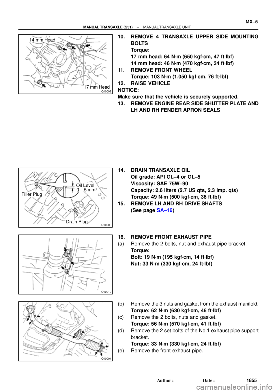
10. REMOVE 4 TRANSAXLE UPPER SIDE MOUNTING
BOLTS
Torque:
17 mm head: 64 N´m (650 kgf´cm, 47 ft´lbf)
14 mm head: 46 N´m (470 kgf´cm, 34 ft´lbf)
11. REMOVE FRONT WHEEL
Torque: 103 N´m (1,050 kgf´cm, 76 ft´lbf)
12. RAISE VEHICLE
NOTICE:
Make sure that the vehicle is securely supported.
13. REMOVE ENGINE REAR SIDE SHUTTER PLATE AND
LH AND RH FENDER APRON SEALS
14. DRAIN TRANSAXLE OIL
Oil grade: API GL±4 or GL±5
Viscosity: SAE 75W±90
Capacity: 2.6 liters (2.7 US qts, 2.3 Imp. qts)
Torque: 49 N´m (500 kgf´cm, 36 ft´lbf)
15. REMOVE LH AND RH DRIVE SHAFTS
(See page SA±16)
16. REMOVE FRONT EXHAUST PIPE
(a) Remove the 2 bolts, nut and exhaust pipe bracket.
Torque:
Bolt: 19 N´m (195 kgf´cm, 14 ft´lbf)
Nut: 33 N´m (330 kgf´cm, 24 ft´lbf)
(b) Remove the 3 nuts and gasket from the exhaust manifold.
Torque: 62 N´m (630 kgf´cm, 46 ft´lbf)
(c) Remove the 2 bolts, nuts and gasket.
Torque: 56 N´m (570 kgf´cm, 41 ft´lbf)
(d) Remove the 2 set bolts of the No.1 exhaust pipe support
bracket.
Torque: 33 N´m (330 kgf´cm, 24 ft´lbf)
(e) Remove the front exhaust pipe.
Page 3767 of 4770
MX04E±01
MX±8
± MANUAL TRANSAXLE (S51)MANUAL TRANSAXLE UNIT
1858 Author�: Date�:
INSTALLATION
Installation is in the reverse order of removal (See page MX±4).
HINT:
�Front wheel alignment (See page SA±4).
�Do the road test.
Page 3805 of 4770

MX04Z±01
Q09981
Hood
14 (150, 10)
w/ Cruise Control :
Cruise Control Actuator
12 (120, 9)
Clutch Line Bracket
21 (210, 15)
12 (120, 9)
Clutch Release Cylinder
26 (270, 20)
RH Drive Shaft�
�32 (330, 24)
7.8 (80, 69 in.´lbf)
Flywheel Housing Under CoverRH Fender
Apron SealClutch Accumulator
Vehicle Speed Sensor
Connector
46 (470, 34)
Engine LH Mounting
Insulator with Bracket
Rear RH Suspension Member Brace
37 (380, 27)
Transaxle
64 (650, 47)
36 (370, 27)
10 (100, 7)
Steering Return Pipe
19 (195, 14)
32 (330, 24)
181 (1,850, 134)
Silver Bolt : 44 (450, 33)
Green Bolt : 66 (670, 48)
Suspension Member with
Lower Suspension Arm
Front RH Suspension
Member Brace
181 (1,850, 134)
Control
Cable
Clip13 (130, 9)
Clip
Washer
Starter
21 (210, 15)
39 (400, 29)
Air Cleaner
Case Assembly
with Air Hose
64 (650, 47)Ground Cable
x5Back±Up Light Switch Connector
Engine Wire
20 (200, 14)Hold±Down
Clamp
Battery
LH Drive Shaft
LH Fender Apron Seal RH Exhaust Manifold Stay
64 (650, 47)
181 (1,850, 134)PS Gear Assembly
No.1 Fuel Tube Protector
49 (500, 36)
294 (3,000, 217)
Lock Cap
Rear LH Suspension Member Brace
Stabilizer Bar Link
Hole
Plug
127 (1,300, 94)
39 (400, 29)
80 (820, 59)48 (490, 35)
Silver Bolt : 44 (450, 33)
Green Bolt : 66 (670, 48)
Front LH Suspension
Member Brace RH Fender
Liner
Engine Rear Side
Shutter Plate
56 (570, 41)
�
�
62 (630, 46) �
62 (630, 46) �
Front Exhaust Pipe
No.1 Exhaust Pipe
Support Bracket
33 (330, 24)
Exhaust Pipe Support Stay
33 (330, 24)LH Fender
Liner
66 (670, 48)
Snap Ring
�Snap Ring
�Cotter Pin
�Cotter Pin
�Gasket
�Gasket
�Gasket
Non±reusable part: Specified torque
N´m (kgf´cm, ft´lbf)
�
36 (370, 27)
± MANUAL TRANSAXLE (E153)MANUAL TRANSAXLE UNIT
MX±3
1804 Author�: Date�:
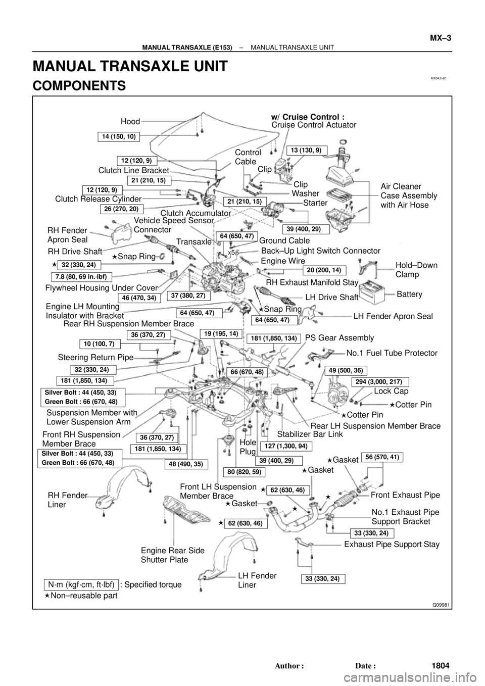
MANUAL TRANSAXLE UNIT
COMPONENTS
Page 3807 of 4770

Q09986
Q09987
Filler Plug
Oil Level
0 ± 5 mm
Drain Plug
Q09988
± MANUAL TRANSAXLE (E153)MANUAL TRANSAXLE UNIT
MX±5
1806 Author�: Date�:
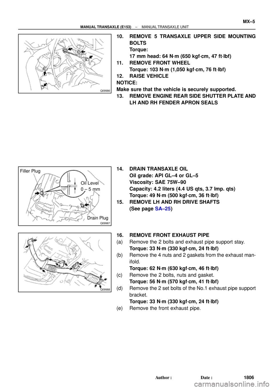
10. REMOVE 5 TRANSAXLE UPPER SIDE MOUNTING
BOLTS
Torque:
17 mm head: 64 N´m (650 kgf´cm, 47 ft´lbf)
11. REMOVE FRONT WHEEL
Torque: 103 N´m (1,050 kgf´cm, 76 ft´lbf)
12. RAISE VEHICLE
NOTICE:
Make sure that the vehicle is securely supported.
13. REMOVE ENGINE REAR SIDE SHUTTER PLATE AND
LH AND RH FENDER APRON SEALS
14. DRAIN TRANSAXLE OIL
Oil grade: API GL±4 or GL±5
Viscosity: SAE 75W±90
Capacity: 4.2 liters (4.4 US qts, 3.7 Imp. qts)
Torque: 49 N´m (500 kgf´cm, 36 ft´lbf)
15. REMOVE LH AND RH DRIVE SHAFTS
(See page SA±25)
16. REMOVE FRONT EXHAUST PIPE
(a) Remove the 2 bolts and exhaust pipe support stay.
Torque: 33 N´m (330 kgf´cm, 24 ft´lbf)
(b) Remove the 4 nuts and 2 gaskets from the exhaust man-
ifold.
Torque: 62 N´m (630 kgf´cm, 46 ft´lbf)
(c) Remove the 2 bolts, nuts and gasket.
Torque: 56 N´m (570 kgf´cm, 41 ft´lbf)
(d) Remove the 2 set bolts of the No.1 exhaust pipe support
bracket.
Torque: 33 N´m (330 kgf´cm, 24 ft´lbf)
(e) Remove the front exhaust pipe.
Page 3809 of 4770

Q09994
Q09995
Q09996
CA
C
A
CB
AAB
C
Q09997
14 mm Head B14 mm Head B
14 mm Head A
± MANUAL TRANSAXLE (E153)MANUAL TRANSAXLE UNIT
MX±7
1808 Author�: Date�:
21. REMOVE LH ENGINE MOUNTING INSULATOR WITH
BRACKET
(a) Remove the 2 hole plugs, nuts and 3 bolts.
Torque:
Bolt: 64 N´m (650 kgf´cm, 47 ft´lbf)
Nut: 80 N´m (820 kgf´cm, 59 ft´lbf)
(b) Lift up the transaxle and remove the left engine mounting
insulator with the bracket.
22. REMOVE HOLE PLUG AND 4 ENGINE REAR SIDE
MOUNTING NUTS
Torque: 66 N´m (670 kgf´cm, 48 ft´lbf)
23. ATTACH ENGINE SLING DEVICE TO ENGINE HANG-
ER
(See page EM±69)
24. DISCONNECT STEERING RETURN PIPE FROM
FRONT SUSPENSION MEMBER
Remove the 2 bolts.
Torque: 10 N´m (100 kgf´cm, 7 ft´lbf)
25. REMOVE FRONT SUSPENSION MEMBER WITH LOW-
ER SUSPENSION ARM
(a) Remove the LH and RH fender liner set screws.
(b) Remove the 6 bolts, 4 nuts, front LH and RH suspension
member braces, rear LH and RH suspension member
braces and front suspension member with the lower sus-
pension arm.
Torque:
Bolt A: 181 N´m (1,850 kgf´cm, 134 ft´lbf)
Bolt B: 32 N´m (330 kgf´cm, 24 ft´lbf)
Nut C: 36 N´m (370 kgf´cm, 27 ft´lbf)
26. JACK UP TRANSAXLE SLIGHTLY
Using a transmission jack, support the transaxle.
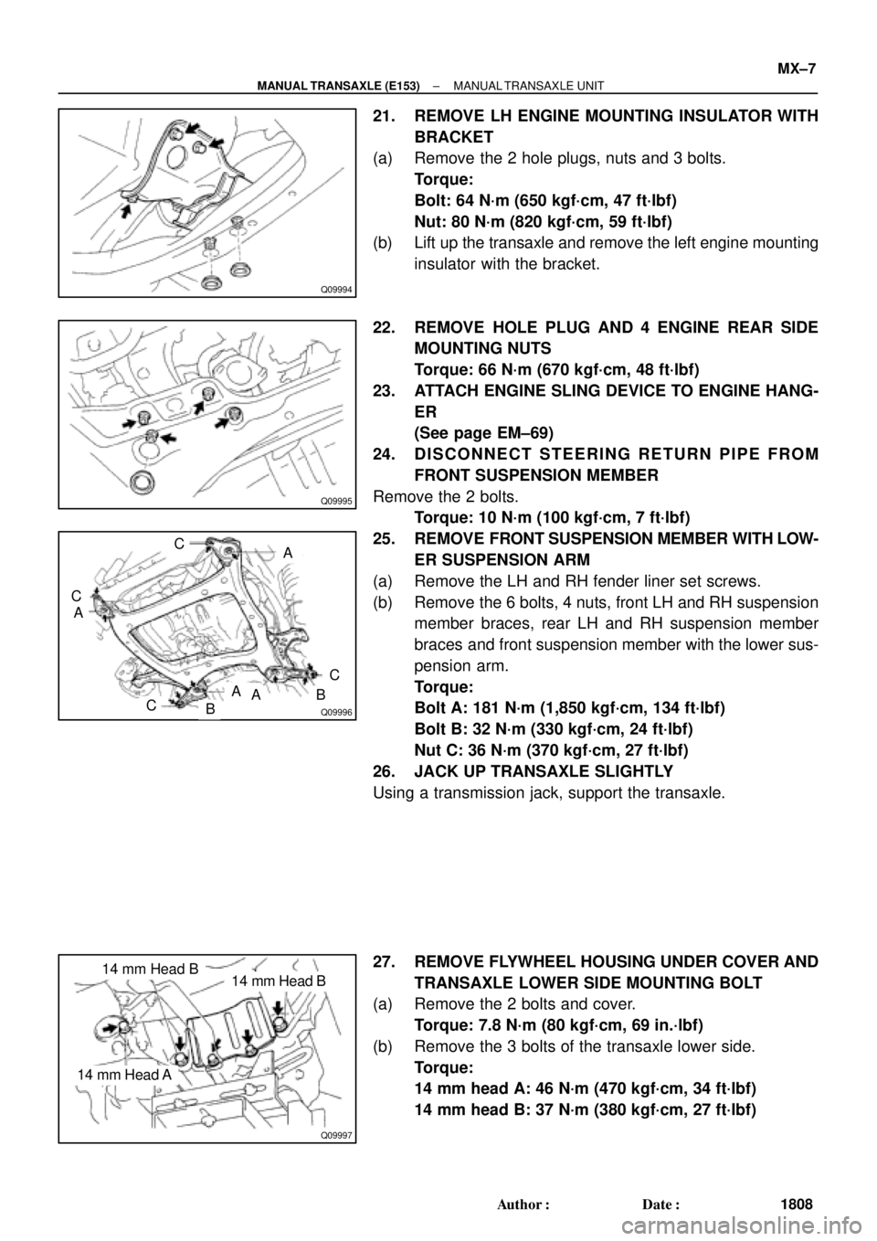
27. REMOVE FLYWHEEL HOUSING UNDER COVER AND
TRANSAXLE LOWER SIDE MOUNTING BOLT
(a) Remove the 2 bolts and cover.
Torque: 7.8 N´m (80 kgf´cm, 69 in.´lbf)
(b) Remove the 3 bolts of the transaxle lower side.
Torque:
14 mm head A: 46 N´m (470 kgf´cm, 34 ft´lbf)
14 mm head B: 37 N´m (380 kgf´cm, 27 ft´lbf)
Page 3811 of 4770
MX051±01
± MANUAL TRANSAXLE (E153)MANUAL TRANSAXLE UNIT
MX±9
1810 Author�: Date�:
INSTALLATION
Installation is in the reverse order of removal (See page MX±4).
HINT:
After installation, check and inspect items as follows.
�Front wheel alignment (See page SA±4).
�Do the road test.
Page 3858 of 4770
PP1WA±02
± PREPARATIONENGINE MECHANICAL (5S±FE)
PP±7
59 Author�: Date�:
SSM (Special Service Materials)
08826±00080Seal Packing Black or equivalent
(FIPG)Camshaft bearing cap
Cylinder head cover
Semi±circular plug
08833±00070Adhesive 1324,
THREE BOND 1324 or equivalentFlywheel or drive plate bolt
Torque converter clutch bolt
08833±00080Adhesive 1344
THREE BOND 1344
LOCTITE 242 or equivalentOil pressure switch
Page 3951 of 4770
PP0MS±01
PP±100
± PREPARATIONSUPPLEMENTAL RESTRAINT SYSTEM
152 Author�: Date�:
EQUIPMENT
Torque wrench
Bolt: Length: 35 mm (1.38 in.) Pitch: 1.0 mm (0.039 in.)
Diam.: 6.0 mm (0.236 in.)Airbag disposal
Tire Width: 185 mm (7.28 in.) Inner diam.: 360mm (14.17 in.)Airbag disposal
Tire with disc wheel Width: 185 mm (7.28 in.)
Inner diam.: 360 mm (14.17 in.)Airbag disposal
Vinyl bagAirbag disposal