Page 4641 of 4770

CA/50 STATE CERTIFIED EMISSION CONTROL UNDERHOOD LABEL ORDERING ± PG006±00 March 31, 2000
Page 6 of 6
MODELENGINE NAMETRANSMISSIONEMISSIONS*PART NUMBERS
ECHO1NZ±FEAllUSA11298±21010
Corolla1ZZ±FEAllUSA11298±22032
Celica
1ZZ±FEAllUSA11298±22080
Celica
2ZZ±GEAllUSA11298±22050
5S±FEAllUSA11298±7A590
Camry1MZ±FEM/TMUSA11298±20320
1MZ±FEA/TMCA11298±20310
5S±FEAllUSA11298±7A590
Camry Solara1MZ±FEM/TMUSA11298±20320
1MZ±FEA/TMCA11298±20310
Camry Solara5S±FEA/TMUSA11298±7A590Camry Solara
Convertible1MZ±FEA/TMCA11298±20310
Camry (CNG)5S±FNEA/TMUSA11298±7A640
Avalon1MZ±FEA/TMUSA11298±20290
Sienna1MZ±FEA/TMUSA11298±20340
RAV43S±FE (2WD/4WD)AllUSA11298±7A620
3RZ±FE (2WD)AllUSA11298±75550
4Runner3RZ±FE (4WD)M/TMUSA11298±75550
5VZ±FE (2WD/4WD)AllUSA11298±62690
2RZ±FE (2WD)AllUSA11298±75510
3RZ±FE (2WD/4WD)A/TMUSA11298±75530
3RZ±FE
(4WD XtraCab)M/TMUSA11298±75530
Tacoma
3RZ±FE
(4WD XtraCab)A/TMUSA11298±75550
3RZ±FE
(PreRunner)A/TMUSA11298±75530
5VZ±FE
(2WD XtraCab)AllUSA11298±62670
5VZ±FE
(4WD & PreRunner)AllUSA11298±62690
T ndra
5VZ±FEAllCA11298±62640
Tundra
2UZ±FEA/TMUSA11298±50241
Land Cruiser2UZ±FEA/TMUSA11298±50182
* CA = California Emission Specification, USA = 50 State Emission Specification
2000 MY CA/50
State Certified
Emission
Control Labels
Page 4645 of 4770

WARRANTY PARTS MARKING PROCEDURE ± PG006-03September 26, 2003
Page 2 of 3
Dealers are requested to mark the location of the failure of all warranty parts that are
listed below.
This list is not inclusive. There may be other components that can be
marked in the area of failure. All other parts that can be marked should be marked.
assist grip assy headlamps
audio (blemish) headliner
back door garnish hoses
bumper covers instrument panel safety pad sub±assy
cargo cover (retractable) Interior light assemblies and covers
carpet knobs, levers, handles
clutch disc l/pulley pump assy
clutch flywheel mirrors (side and rearview)
combination meter glass navigation or VES screens
console and components pillar garnish
cowl assy rack and pinion/power steering gear assy
cowl side trim sub±assy radiator
cupholders room partition board
cylinder head cover sub±assy rotors (mark where min. runout is exceeded or warped)
dash panel insulator assy seat covers/cushions
dashboard and trim seat tracks
disc wheel soft trim
display panels spare tire cover
door handle assy steering column cover
door moulding steering wheel
door trim panel & molding tail lamps and covers
emblems transmission oil pan
engine oil pan visor
exhaust manifold washer jar
floor and cargo mats wheel cap
gear shift knob wheels
grills
Parts
Marking
Requirement
Parts
Marking
List
Page 4646 of 4770
WARRANTY PARTS MARKING PROCEDURE ± PG006-03September 26, 2003
Page 3 of 3
NOTE:
The following parts do not have to be marked unless the technician can determine
failure and location.
air induction/ejection systems fuel injection systems
all computers fuel injectors
alternators fuel pump
audio (internal) ignition system
batteries internal engine components
bearings internal transmission components
belts oil cooler
catalytic converter power door lock switches
crankshaft remanufactured parts
cruise control starters
distributors suspension components
EGR systems valve covers
engine control systems window regulators
exchange parts wiper motors
exhaust systems
Parts
Marking
List
(Continued)
Page 4703 of 4770

Toyota Supports ASE CertificationPage 1 of 1
TC001-02Title:
AUTOMATIC TRANSMISSION FLUID
REQUIREMENTS
Models:
All '00 ± '02 Models & '03 Corolla & Matrix
Technical Service
BULLETIN
May 24, 2002
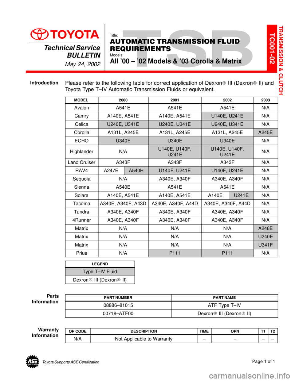
Please refer to the following table for correct application of Dexron
� III (Dexron� II) and
Toyota Type T±IV Automatic Transmission Fluids or equivalent.
MODEL2000200120022003
AvalonA541EA541EA541EN/A
CamryA140E, A541EA140E, A541EU140E, U241EN/A
CelicaU240E, U341EU240E, U341EU240E, U341EN/A
CorollaA131L, A245EA131L, A245EA131L, A245EA245E
ECHOU340EU340EU340EN/A
HighlanderN/AU140E, U140F,
U241EU140E, U140F,
U241EN/A
Land CruiserA343FA343FA343FN/A
RAV4A247EA540HU140F, U241EU140F, U241EN/A
SequoiaN/AA340E, A340FA340E, A340FN/A
SiennaA540EA541EA541EN/A
SolaraA140E, A541EA140E, A541EA140EU241EN/A
TacomaA340E, A340F, A43DA340E, A340F, A44DA340E, A340F, A44DN/A
TundraA340E, A340FA340E, A340FA340E, A340FN/A
4RunnerA340E, A340FA340E, A340FA340E, A340FN/A
MatrixN/AN/AN/AA246E
MatrixN/AN/AN/AU240E
MatrixN/AN/AN/AU341F
PriusN/AP111P111N/A
LEGEND
Type T±IV Fluid
Dexron� III (Dexron� II)
PART NUMBERPART NAME
08886±81015ATF Type T±IV
00718±ATF00Dexron� III (Dexron� II)
OP CODEDESCRIPTIONTIMEOPNT1T2
N/ANot Applicable to Warranty±±±±
TRANSMISSION & CLUTCH
Introduction
Parts
Information
Warranty
Information
Page 4704 of 4770

Toyota Supports ASE CertificationPage 1 of 1
TC002±99Title:
REVISED DRIVE SHAFT GREASE
Models:
RAV4, Tercel, Corolla, Celica, Camry & Supra
Technical Service
BULLETIN
April 9, 1999
The greases supplied in replacement Inboard and Outboard Drive Shaft Boot Kits for the
following models has been revised.
With this revision, the grease compositions have been changed and are now both the
same color. To correctly lubricate each joint, consult the Service Repair Manual as to
which size packet of grease is designated for each Drive Shaft Joint Assembly.
NOTE:
Although Inboard and Outboard greases are now the same color, their compositions
are different.
�All RAV4, Tercel, Corolla, Celica, Camry and Supra Models.
As outlined in the Service Repair Manual.
Refer to the appropriate Repair Manual for installation and lubrication information for
Drive Shaft Joint Assemblies.
OP CODEDESCRIPTIONTIMEOPNT1T2
N/ANot Applicable to Warranty ±±±±
TRANSMISSION & CLUTCH
Introduction
Affected
Vehicles
Required
Tools and
Material
Repair
Procedure
Warranty
Information
Page 4705 of 4770

TSB
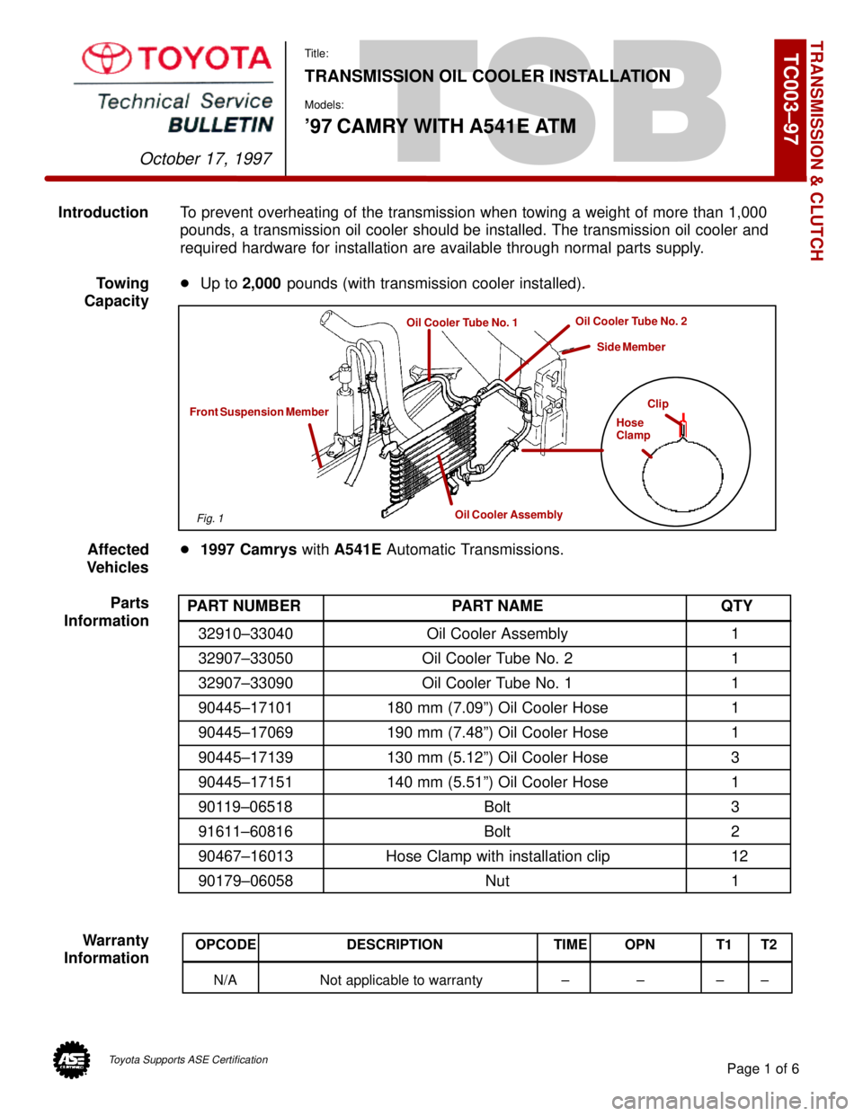
IntroductionTo prevent overheating of the transmission when towing a weight of more than 1,000
pounds, a transmission oil cooler should be installed. The transmission oil cooler and
required hardware for installation are available through normal parts supply.
Towing�Up to 2,000 pounds (with transmission cooler installed).
Capacity
Affected�1997 Camrys with A541E Automatic Transmissions.
Vehicles
Parts
Information
Warranty
Information
TRANSMISSION & CLUTCH
October 17, 1997
Title:
TRANSMISSION OIL COOLER INSTALLATION
Models:
'97 CAMRY WITH A541E ATM
Page 1 of 6
TC003±97
Clip
Hose
Clamp
Oil Cooler Assembly
Front Suspension Member
Oil Cooler Tube No. 1Oil Cooler Tube No. 2
Side Member
PART NUMBER PART NAME QTY
32910±33040 Oil Cooler Assembly 1
32907±33050 Oil Cooler Tube No. 2 1
32907±33090 Oil Cooler Tube No. 1 1
90445±17101 180 mm (7.09º) Oil Cooler Hose 1
90445±17069 190 mm (7.48º) Oil Cooler Hose 1
90445±17139 130 mm (5.12º) Oil Cooler Hose 3
90445±17151 140 mm (5.51º) Oil Cooler Hose 1
90119±06518 Bolt 3
91611±60816 Bolt 2
90467±16013 Hose Clamp with installation clip 12
90179±06058 Nut 1
OPCODE DESCRIPTION TIME OPN T1 T2
N/A Not applicable to warranty ± ± ± ±
Fig. 1
Toyota Supports ASE Certification
Page 4706 of 4770
TRANSMISSION OIL COOLER INSTALLATION ± TC003±97 October 17, 1997
Procedure1. Parts removal in preparation for cooler
installation:
A. Remove the 9 bolts, 2 screws and
the center engine under cover.
B. Remove the engine coolant
temperature switch connector and
the wire clamp.
C. Remove battery and tray.
D. Disconnect the cooling fan
connector.
E. Disconnect the No.1 engine coolant
temperature switch wire connector.
F. Remove the 2 bolts and then the
cooling fan.
Page 2 of 6
Fig. 2Center Engine Under Cover
Fig. 3ClampSwitch
Fig. 4
Page 4707 of 4770
Page 3 of 6
TRANSMISSION OIL COOLER INSTALLATION ± TC003±97 October 17, 1997
Procedure2. Cooler Installation:
(Continued)
A. Install the 140 mm (5.51º) hose to
the oil cooler tube No. 1 as shown.
NOTE:
Install the hose clamp with the hose
clamp clip at the position shown, and
use pliers to pull off the clip in the
direction indicated by the arrow.
B. Install the tube bracket onto the left
side of the front suspension
member with the 2 bolts as shown.
Torque: 62 in±lbf
(7 N±m / 71 kgf±cm)
C. Install the 130 mm (5.12º) hoses
and the 180 mm (7.09º) hose to the
oil cooler tube No. 2 as shown.
NOTE:
Install the hose clamps with the hose
clamp clips at the positions shown,
and use pliers to pull off the clips in
the direction indicated by the arrows.
Fig. 5
Oil Cooler Tube No. 1
140 mm Hose
5 mm (0.20º)
Fig. 6
Fig. 7
5 mm (0.20º)
180 mm Hose Oil Cooler Tube No. 2
130 mm Hose