Page 4538 of 4770

READINESS MONITOR DRIVE PATTERNS ± EG003-02 RevisedMarch 29, 2002
Page 7 of 23
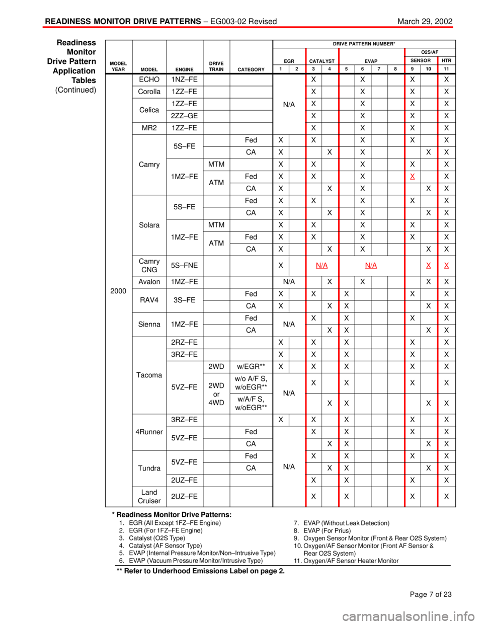
DRIVE PATTERN NUMBER*
O2S/AF
MODELDRIVEEGRCATALYSTEVAPSENSORHTRMODELYEARMODELENGINEDRIVETRAINCATEGORY1234567891011
ECHO1NZ±FEXXXX
Corolla1ZZ±FEXXXX
Celica1ZZ±FEN/AXXXXCelica2ZZ±GEXXXX
MR21ZZ±FEXXXX
5S FEFedXXXXX5S±FECAXXXXX
CamryMTMXXXXXy
1MZ±FEATMFedXXXXXATMCAXXXXX
5S FEFedXXXXX5S±FECAXXXXX
SolaraMTMXXXXX
1MZ±FEATMFedXXXXXATMCAXXXXX
Camry
CNG5S±FNEXN/AN/AXX
Avalon1MZ±FEN/AXXXX
2000
RAV43S FEFedXXXXXRAV43S±FECAXXXXX
Sienna1MZ FEFedN/AXXXXSienna1MZ±FECAN/AXXXX
2RZ±FEXXXXX
3RZ±FEXXXXX
T
2WDw/EGR**XXXXX
Tacoma
5VZ±FE2WD
or
w/o A/F S,
w/oEGR**
N/A
XXXX
or
4WDw/A/F S,
w/oEGR**N/A
XXXX
3RZ±FEXXXXX
4Runner5VZ FEFedXXXX5VZ±FECAXXXX
5VZ FEFedXXXX
Tundra5VZ±FECAN/AXXXX
2UZ±FEXXXX
Land
Cruiser2UZ±FEXXXX
* Readiness Monitor Drive Patterns:
1. EGR (All Except 1FZ±FE Engine)
2. EGR (For 1FZ±FE Engine)
3. Catalyst (O2S Type)
4. Catalyst (AF Sensor Type)
5. EVAP (Internal Pressure Monitor/Non±Intrusive Type)
6. EVAP (Vacuum Pressure Monitor/Intrusive Type)7. EVAP (Without Leak Detection)
8. EVAP (For Prius)
9. Oxygen Sensor Monitor (Front & Rear O2S System)
10. Oxygen/AF Sensor Monitor (Front AF Sensor &
Rear O2S System)
11. Oxygen/AF Sensor Heater Monitor
** Refer to Underhood Emissions Label on page 2.
Readiness
Monitor
Drive Pattern
Application
Tables
(Continued)
Page 4539 of 4770

READINESS MONITOR DRIVE PATTERNS ± EG003-02 RevisedMarch 29, 2002
Page 8 of 23
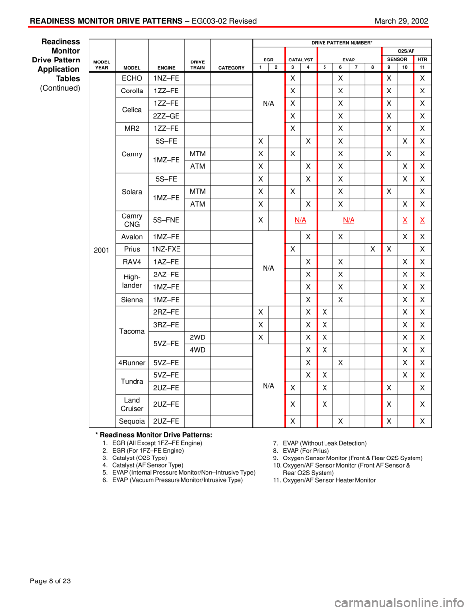
DRIVE PATTERN NUMBER*
O2S/AF
MODELDRIVEEGRCATALYSTEVAPSENSORHTRMODELYEARMODELENGINEDRIVETRAINCATEGORY1234567891011
ECHO1NZ±FEXXXX
Corolla1ZZ±FEXXXX
Celica1ZZ±FEN/AXXXXCelica2ZZ±GEXXXX
MR21ZZ±FEXXXX
5S±FEXXXXX
Camry1MZ FEMTMXXXXXy1MZ±FEATMXXXXX
5S±FEXXXXX
Solara1MZ FEMTMXXXXX1MZ±FEATMXXXXX
Camry
CNG5S±FNEXN/AN/AXX
Avalon1MZ±FEXXXX
2001Prius1NZ-FXEXXXX
RAV41AZ±FEN/AXXXX
High-2AZ±FEN/AXXXXHigh
lander1MZ±FEXXXX
Sienna1MZ±FEXXXX
2RZ±FEXXXXX
Tacoma3RZ±FEXXXXXTacoma
5VZ FE2WDXXXXX5VZ±FE4WDXXXX
4Runner5VZ±FEXXXX
Tundra5VZ±FEXXXXTundra2UZ±FEN/AXXXX
Land
Cruiser2UZ±FEXXXX
Sequoia2UZ±FEXXXX
* Readiness Monitor Drive Patterns:
1. EGR (All Except 1FZ±FE Engine)
2. EGR (For 1FZ±FE Engine)
3. Catalyst (O2S Type)
4. Catalyst (AF Sensor Type)
5. EVAP (Internal Pressure Monitor/Non±Intrusive Type)
6. EVAP (Vacuum Pressure Monitor/Intrusive Type)7. EVAP (Without Leak Detection)
8. EVAP (For Prius)
9. Oxygen Sensor Monitor (Front & Rear O2S System)
10. Oxygen/AF Sensor Monitor (Front AF Sensor &
Rear O2S System)
11. Oxygen/AF Sensor Heater Monitor
Readiness
Monitor
Drive Pattern
Application
Tables
(Continued)
Page 4540 of 4770

READINESS MONITOR DRIVE PATTERNS ± EG003-02 RevisedMarch 29, 2002
Page 9 of 23
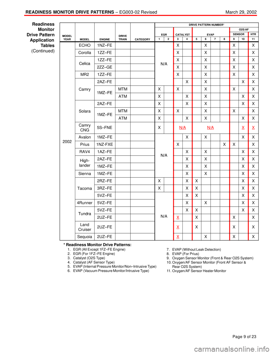
DRIVE PATTERN NUMBER*
O2S/AF
MODELDRIVEEGRCATALYSTEVAPSENSORHTRMODELYEARMODELENGINEDRIVETRAINCATEGORY1234567891011
ECHO1NZ±FEXXXX
Corolla1ZZ±FEXXXX
Celica1ZZ±FEN/AXXXXCelica2ZZ±GEN/AXXXX
MR21ZZ±FEXXXX
2AZ±FEXXXX
Camry1MZ FEMTMXXXXXy1MZ±FEATMXXXXX
2AZ±FEXXXXX
Solara1MZ FEMTMXXXXX1MZ±FEATMXXXXX
Camry
CNG5S±FNEXN/AN/AXX
2002
Avalon1MZ±FEXXXX
2002Prius1NZ-FXEXXXX
RAV41AZ±FEN/AXXXX
High-2AZ±FEN/AXXXXHigh
lander1MZ±FEXXXX
Sienna1MZ±FEXXXX
2RZ±FEXXXXX
Tacoma3RZ±FEXXXXX
5VZ±FEXXXX
4Runner5VZ±FEXXXX
Tundra5VZ±FEXXXXTundra2UZ±FEN/AXXXX
Land
Cruiser2UZ±FEXXXX
Sequoia2UZ±FEXXXX
* Readiness Monitor Drive Patterns:
1. EGR (All Except 1FZ±FE Engine)
2. EGR (For 1FZ±FE Engine)
3. Catalyst (O2S Type)
4. Catalyst (AF Sensor Type)
5. EVAP (Internal Pressure Monitor/Non±Intrusive Type)
6. EVAP (Vacuum Pressure Monitor/Intrusive Type)7. EVAP (Without Leak Detection)
8. EVAP (For Prius)
9. Oxygen Sensor Monitor (Front & Rear O2S System)
10. Oxygen/AF Sensor Monitor (Front AF Sensor &
Rear O2S System)
11. Oxygen/AF Sensor Heater Monitor
Readiness
Monitor
Drive Pattern
Application
Tables
(Continued)
Page 4554 of 4770

READINESS MONITOR DRIVE PATTERNS ± EG003-02 RevisedMarch 29, 2002
Page 23 of 23
DRIVE PATTERN NO. 11: Oxygen/AF Sensor Heater Monitor
Idling
IG SW off
2 min
(b) 9 min
(a) 25 mph
(40 km/h)
Preconditions
The monitor will not run unless:
�MIL is OFF.
Drive Pattern Procedure
Connect the OBDII Scantool to DLC3 to check monitor status and preconditions.
a. Start the engine and allow it to idle for 9 minutes.
b. Drive the vehicle at 25 mph (40 km/h) or more for at least 2 minutes.
If readiness status does not switch to ªcomplete,º ensure preconditions are met, turn the
ignition OFF, then repeat steps ªaº and ªb.º
NOTE:
The readiness status may not switch to ªcompleteº after the first drive pattern trip if a
Pending Code has been set (first trip for a two±trip DTC).
�Pending Codes are available from the DTC Info Menu in Enhanced OBDII.
�Pending Codes indicate a POTENTIAL problem was detected. A second trip is
needed to confirm the DTC prior to diagnosis.
�Once a second trip is completed, a current DTC will be stored. Readiness
Monitor
Drive
Patterns:
Oxygen
Monitors
(Continued)
Page 4583 of 4770

Toyota Supports ASE CertificationPage 1 of 2
EL002±98Title:
CIGARETTE LIGHTER SERVICE
Models:
All Models
Technical Service
BULLETIN
Apirl 10, 1998
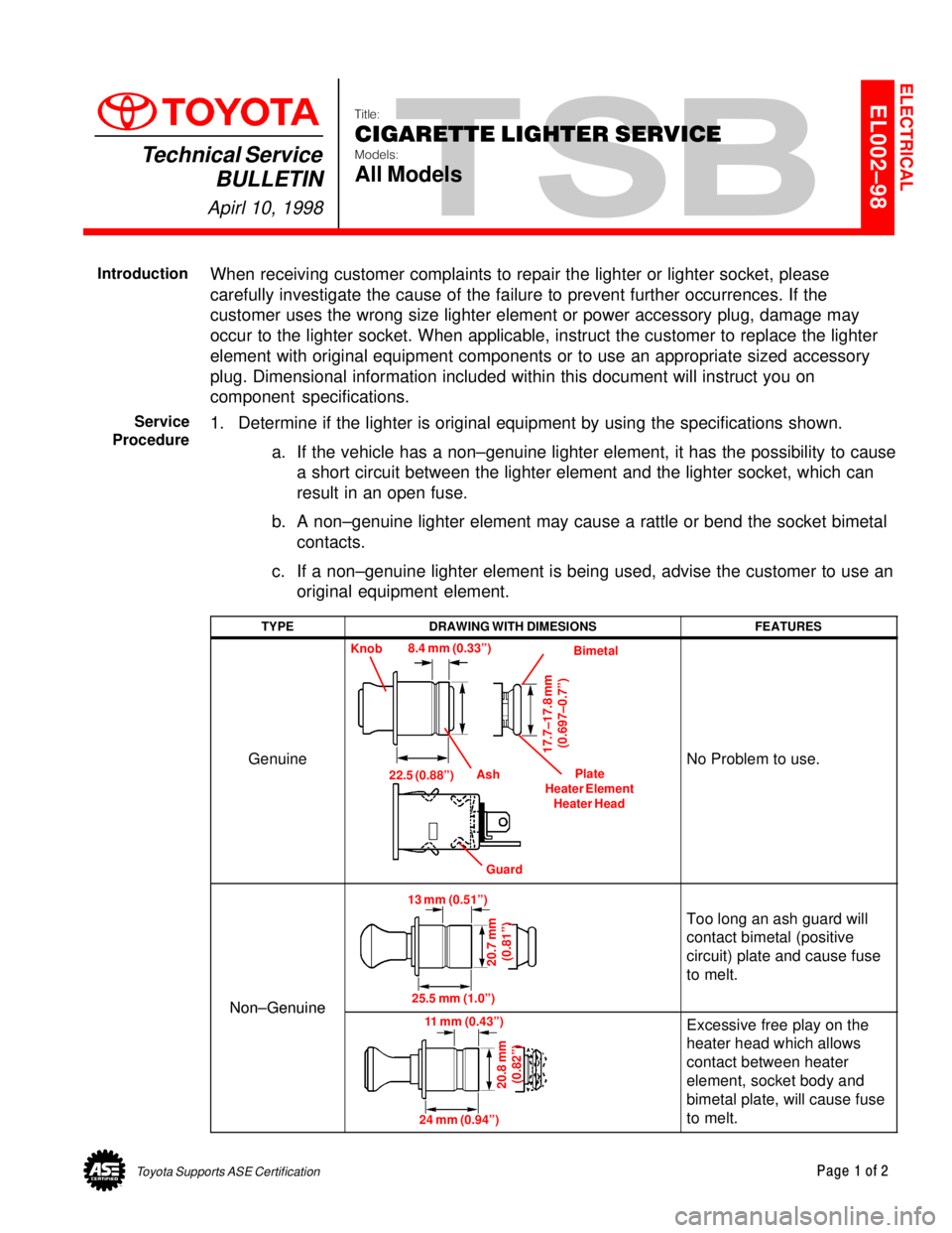
When receiving customer complaints to repair the lighter or lighter socket, please
carefully investigate the cause of the failure to prevent further occurrences. If the
customer uses the wrong size lighter element or power accessory plug, damage may
occur to the lighter socket. When applicable, instruct the customer to replace the lighter
element with original equipment components or to use an appropriate sized accessory
plug. Dimensional information included within this document will instruct you on
component specifications.
1. Determine if the lighter is original equipment by using the specifications shown.
a. If the vehicle has a non±genuine lighter element, it has the possibility to cause
a short circuit between the lighter element and the lighter socket, which can
result in an open fuse.
b. A non±genuine lighter element may cause a rattle or bend the socket bimetal
contacts.
c. If a non±genuine lighter element is being used, advise the customer to use an
original equipment element.
TYPEDRAWING WITH DIMESIONSFEATURES
Genuine
Knob
Bimetal
Plate
Heater Element
Heater Head
Guard Ash 8.4 mm (0.33º)
17.7±17.8 mm
(0.697±0.7º)
22.5 (0.88º)No Problem to use.
Non±Genuine
13 mm (0.51º)
20.7 mm
(0.81º)
25.5 mm (1.0º)
Too long an ash guard will
contact bimetal (positive
circuit) plate and cause fuse
to melt.
Non±Genuine11 mm (0.43º)
20.8 mm
(0.82º)
24 mm (0.94º)
Excessive free play on the
heater head which allows
contact between heater
element, socket body and
bimetal plate, will cause fuse
to melt.
ELECTRICAL
Introduction
Service
Procedure
Page 4588 of 4770
Toyota Supports ASE CertificationPage 1 of 4
EL007±00Title:
HEATER CONTROL ASSEMBLY
INSTRUCTIONS
Models:
'97 ± '99 Camry
Technical Service
BULLETIN
April 14, 2000
The attached instructions have been developed to supplement the Repair Manual to
assure corrrect cable routing of the heater control assembly during a service repair.
PUBLICATIONNUMBER
1997 Camry Repair Manual, Vol. 2RM503U2
1998 Camry Repair Manual, Vol. 2RM589U2
1999 Camry Repair Manual, Vol. 2RM654U2
NOTE:
For maximum heater performance the coolant ratio should be 50 to 60 percent.
�1997 ± 1999 model year Camry
OP CODEDESCRIPTIONTIMEOPNT1T2
N/ANot Applicable to Warranty ±±±±
ELECTRICAL
Introduction
Applicable
Vehicles
Warranty
Information
Page 4589 of 4770
POOR HEATER PERFORMANCE ± EL007±00 April 14, 2000
Page 2 of 4
A. Pull out the inner cable of the
REC/FRE cable until the link of the
A/C unit contacts the link stopper.
View A
To p
Left Side
RearView A
Link
Should make
contact here.
Link Stopper
B. Set the air intake selector of the
heater control unit all the way to the
ªFRESHº position.
C. Attach the REC/FRE cable to the
heater control unit lever pin and clamp
the outer cable to the secure clamp.
NOTE:
Clamp the cable while pushing the
outer cable to the A/C unit assembly
side. Installation
ProcedureLever
Page 4590 of 4770
POOR HEATER PERFORMANCE ± EL007±00 April 14, 2000
Page 3 of 4
D. Install the heater control panel to the
instrument panel with 4 screws.
NOTE:
Make sure air mix cable is routed
outside of the brace.
REC/FRE Cable
(from A/C Unit)
Step (C)Instrument Panel
Step (A)
Step (D)
Air Mix Cable
Screw (4)
Right Side Front SideTo p
Installation
Procedure
(Continued)