Page 358 of 4770

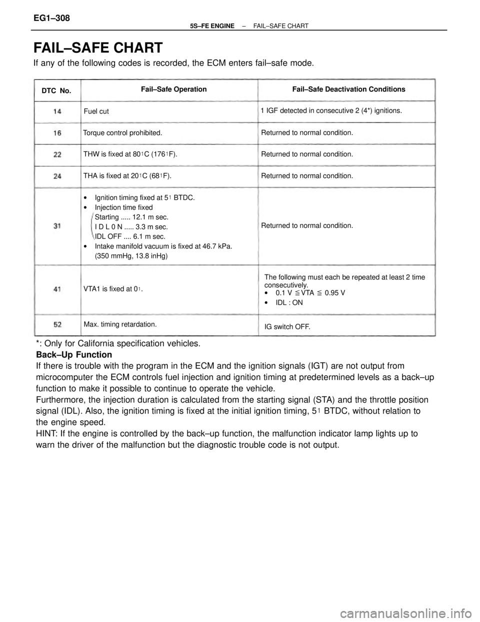
*: Only for California specification vehicles.
Back±Up Function
If there is trouble with the program in the ECM and the ignition signals (IGT) are not output from
microcomputer the ECM controls fuel injection and ignition timing at predetermined levels as a back±up
function to make it possible to continue to operate the vehicle.
Furthermore, the injection duration is calculated from the starting signal (STA) and the throttle position
signal (IDL). Also, the ignition timing is fixed at the initial ignition timing, 5� BTDC, without relation to
the engine speed.
HINT: If the engine is controlled by the back±up function, the malfunction indicator lamp lights up to
warn the driver of the malfunction but the diagnostic trouble code is not output.
FAIL±SAFE CHART
If any of the following codes is recorded, the ECM enters fail±safe mode.
wIgnition timing fixed at 5� BTDC.
wInjection time fixed
Starting ..... 12.1 m sec.
I D L 0 N ..... 3.3 m sec.
IDL OFF .... 6.1 m sec.
wIntake manifold vacuum is fixed at 46.7 kPa.
(350 mmHg, 13.8 inHg)
The following must each be repeated at least 2 time
consecutively.
w0.1 V �VTA � 0.95 V
wIDL : ON 1 IGF detected in consecutive 2 (4*) ignitions.Fail±Safe Deactivation Conditions
THW is fixed at 80�C (176�F).
THA is fixed at 20�C (68�F). Returned to normal condition.Returned to normal condition.
Returned to normal condition. Returned to normal condition. Torque control prohibited.
Max. timing retardation.Fail±Safe Operation
VTA1 is fixed at 0
�.
IG switch OFF. DTC No.
Fuel cut
± 5S±FE ENGINEFAIL±SAFE CHARTEG1±308
Page 359 of 4770

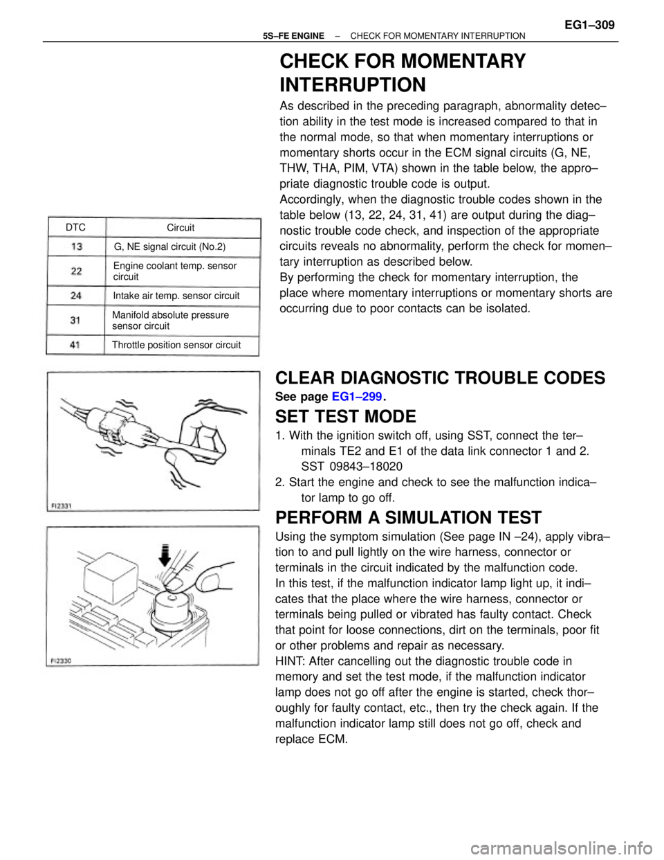
CLEAR DIAGNOSTIC TROUBLE CODES
See page EG1±299.
SET TEST MODE
1. With the ignition switch off, using SST, connect the ter±
minals TE2 and E1 of the data link connector 1 and 2.
SST 09843±18020
2. Start the engine and check to see the malfunction indica±
tor lamp to go off.
PERFORM A SIMULATION TEST
Using the symptom simulation (See page IN ±24), apply vibra±
tion to and pull lightly on the wire harness, connector or
terminals in the circuit indicated by the malfunction code.
In this test, if the malfunction indicator lamp light up, it indi±
cates that the place where the wire harness, connector or
terminals being pulled or vibrated has faulty contact. Check
that point for loose connections, dirt on the terminals, poor fit
or other problems and repair as necessary.
HINT: After cancelling out the diagnostic trouble code in
memory and set the test mode, if the malfunction indicator
lamp does not go off after the engine is started, check thor±
oughly for faulty contact, etc., then try the check again. If the
malfunction indicator lamp still does not go off, check and
replace ECM.
CHECK FOR MOMENTARY
INTERRUPTION
As described in the preceding paragraph, abnormality detec±
tion ability in the test mode is increased compared to that in
the normal mode, so that when momentary interruptions or
momentary shorts occur in the ECM signal circuits (G, NE,
THW, THA, PIM, VTA) shown in the table below, the appro±
priate diagnostic trouble code is output.
Accordingly, when the diagnostic trouble codes shown in the
table below (13, 22, 24, 31, 41) are output during the diag±
nostic trouble code check, and inspection of the appropriate
circuits reveals no abnormality, perform the check for momen±
tary interruption as described below.
By performing the check for momentary interruption, the
place where momentary interruptions or momentary shorts are
occurring due to poor contacts can be isolated.
Engine coolant temp. sensor
circuit
Manifold absolute pressure
sensor circuit
Throttle position sensor circuitIntake air temp. sensor circuitG, NE signal circuit (No.2)Circuit DTC
± 5S±FE ENGINECHECK FOR MOMENTARY INTERRUPTIONEG1±309
Page 401 of 4770
CIRCUIT DESCRIPTION
The signal from the A/T CPU retards the ignition timing of the engine during A/T shifting, thus
momentarily reducing torque output of the engine for smooth clutch operation inside the transmis-
sion and reduced shift shock.
If the ECM detects the diagnostic trouble code ª16º in memory, it prohibits the torque control of the
A/T which performs smooth gear shifting.
Are there any other codes (besides Code 16)
being output?Fault in communications between the engine
CPU and A/T CPU in the ECM
Go to relevant diagnostic trouble code
chart. Diagnostic Trouble Code Detecting Condition
DIAGNOSTIC CHART
Replace ECM.Trouble Area
DTC 16 A±T Control Signal Malfunction
DTC No.
wECM
YES
± 5S±FE ENGINECIRCUIT INSPECTIONEG1±351
Page 404 of 4770
Are there any other codes (besides code 21)
being output ?Go to relevant diagnostic trouble code
chart.
DIAGNOSTIC CHART
WIRING DIAGRAM
Replace main oxygen sensor.YES
± 5S±FE ENGINECIRCUIT INSPECTIONEG1±354
Page 407 of 4770
DIAGNOSTIC CHART
HINT If diagnostic trouble codes ª22º (engine coolant temperature sensor circuit), ª24º (intake air temperature sensor cir-
cuit), ª31º (manifold absolute pressure sensor circuit) and ª41º (throttle position sensor circuit) are output simultaneously, E2
(sensor ground) may be open, OK Check for momentary interruption
Check for open and short in harness and connector
between ECM and engine coolant temp. sensor.Check for momentary interruption
(See page EG1±309).
Repair or replace harness or
connector.Replace engine coolant temp. sensor.
WIRING DIAGRAM
Check resistance of sensor.
Check and replace ECM.Check voltage of sensor.
± 5S±FE ENGINECIRCUIT INSPECTIONEG1±357
Page 408 of 4770
INSPECTION PROCEDURE
HINT: If diagnostic trouble codes ª22º (engine coolant temperature sensor circuit), ª24º (intake air
temperature sensor circuit), ª31º (manifold absolute pressure sensor circuit) and ª41 ª (throttle
position sensor circuit) are output simultaneously, E2 (sensor ground) may be open,
(1) Remove glove compartment
(See page EG1±234)
(2) Turn ignition switch on.
Measure voltage between terminals THW and E2 of engine
control module connector.
Check voltage between terminals THW and E2 of engine control
module connector.
Check for momentary interruption
(See page EG1±309)
Engine Coolant Temp. �C (�F)
20 (68)
( Engine is cool )
80 (176)
(Engine is hot)0.2 ~1.0 v 0.5 ~ 3.4 V Voltage
± 5S±FE ENGINECIRCUIT INSPECTIONEG1±358
Page 410 of 4770

DIAGNOSTIC CHART
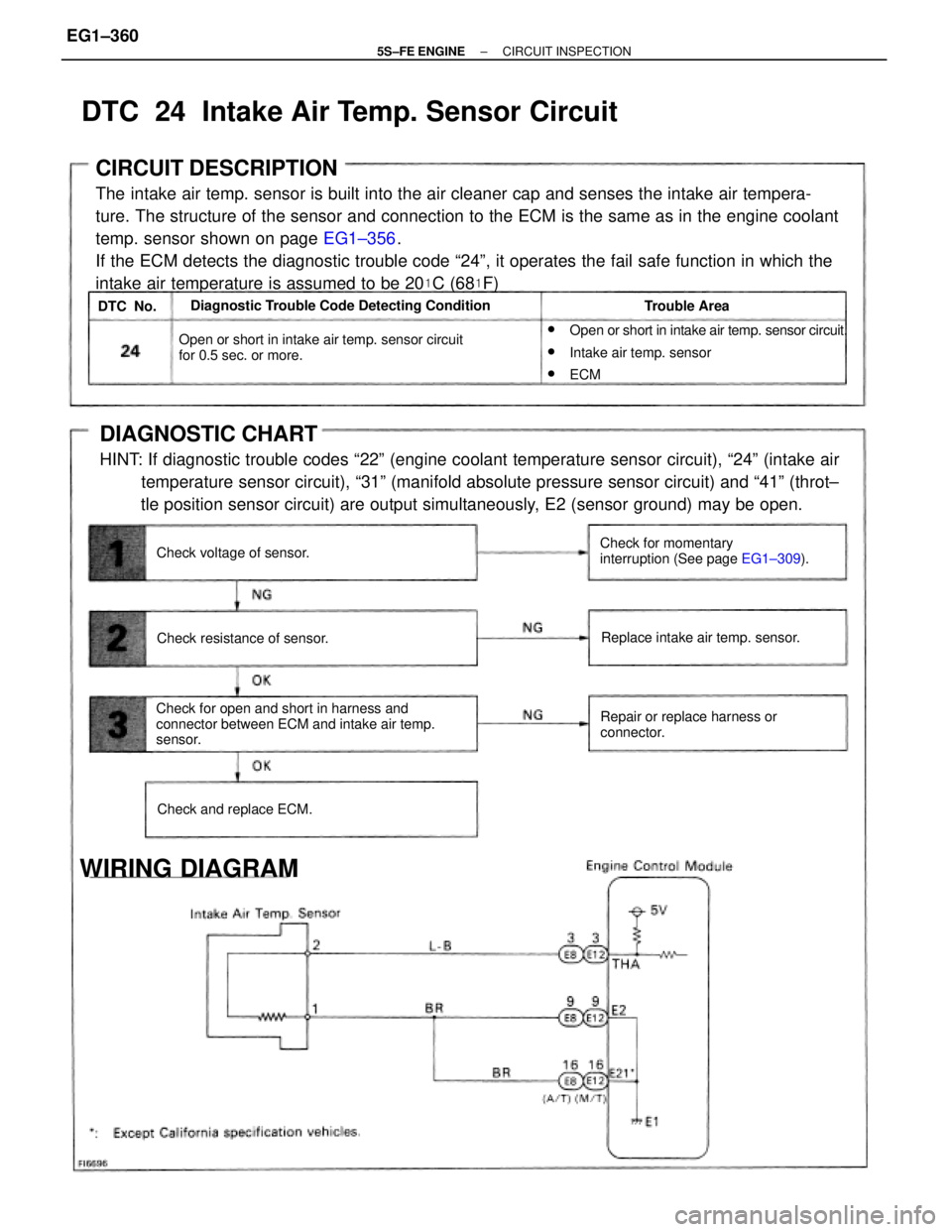
HINT: If diagnostic trouble codes ª22º (engine coolant temperature sensor circuit), ª24º (intake air
temperature sensor circuit), ª31º (manifold absolute pressure sensor circuit) and ª41º (throt±
tle position sensor circuit) are output simultaneously, E2 (sensor ground) may be open.
CIRCUIT DESCRIPTION
The intake air temp. sensor is built into the air cleaner cap and senses the intake air tempera-
ture. The structure of the sensor and connection to the ECM is the same as in the engine coolant
temp. sensor shown on page EG1±356.
If the ECM detects the diagnostic trouble code ª24º, it operates the fail safe function in which the
intake air temperature is assumed to be 20
�C (68�F)
w
Open or short in intake air temp. sensor circuit.
wIntake air temp. sensor
wECM
Check for open and short in harness and
connector between ECM and intake air temp.
sensor.Open or short in intake air temp. sensor circuit
for 0.5 sec. or more.
Check for momentary
interruption (See page EG1±309). Diagnostic Trouble Code Detecting Condition
Repair or replace harness or
connector.Replace intake air temp. sensor.
WIRING DIAGRAM
Check resistance of sensor.
Check and replace ECM. Check voltage of sensor.Trouble Area
DTC 24 Intake Air Temp. Sensor Circuit
DTC No.
± 5S±FE ENGINECIRCUIT INSPECTIONEG1±360
Page 421 of 4770
Are there any other codes (beside Code 27)
being output?Go to relevant diagnostic trouble
code chart.
DIAGNOSTIC CHART
WIRING DIAGRAM
Replace sub oxygen sensor.YES
± 5S±FE ENGINECIRCUIT INSPECTIONEG1±371