Page 1537 of 4770

± AIR CONDITIONINGTROUBLESHOOTING
AC±15
2497 Author�: Date�:
Cool air comes out only at high engine rpm
1. Refrigerant volume
2. Drive belt
3. Magnetic clutch
4. Compressor
5. Condenser
6. Condenser fan
7. Receiver
8. Expansion valve
9. Evaporator
10.Thermistor
11. Refrigerant line
12.Pressure switch
13.*
1 ECM
*2 A/C amplifier
AC±3
AC±16
AC±16
AC±39
AC±52
AC±74
AC±49
AC±59
AC±30
AC±24
AC±21
AC±67
DI±218
AC±88
No engine idle±up when A/C switch ON
1. *1 ECM
*2 A/C amplifier
2. Wire harness
DI±218
AC±88
±
Blinking of A/C indicator
1. *1 ECM
*2 A/C amplifier
2. Thermistor
3. Compressor
DI±218
AC±88
AC±24
AC±39
A/C indicator does not lights up when turn mode switch to DEF.
position
1. A/C Fuse
2. Mode switch
3. A/C switch
4. *
1 ECM
*2 A/C amplifier
5. Wire harness
±
AC±84
AC±84
DI±218
AC±88
±
No warm air comes out
1. Engine coolant volume
2. A/C control assembly
3. Heater radiator±
AC±80
AC±57
No condenser fan operation
1. CDS FAN Fuse
2. Engine main relay
3. Cooling fan relay No. 1
4. Cooling fan relay No. 2
5. Cooling fan relay No. 3
6. Condenser fan motor
7. Pressure switch
8. *
1 Engine coolant temp. switch
*2 No. 1 Engine coolant temp. switch
9. *2No. 2 Engine coolant temp. switch
10.Wire harness
±
±
AC±72
AC±72
AC±72
AC±74
AC±67
AC±92
AC±92
AC±92
±
*1: 5S±FE Engine Models
*
2: 1MZ±FE Engine Models
Page 1538 of 4770
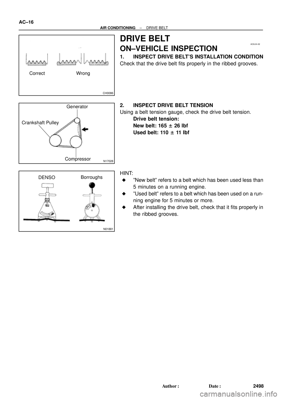
CH0086
Correct Wrong
AC0LM±02
N17028
Generator
Crankshaft Pulley
Compressor
N01881
DENSOBorroughs AC±16
± AIR CONDITIONINGDRIVE BELT
2498 Author�: Date�:
DRIVE BELT
ON±VEHICLE INSPECTION
1. INSPECT DRIVE BELT'S INSTALLATION CONDITION
Check that the drive belt fits properly in the ribbed grooves.
2. INSPECT DRIVE BELT TENSION
Using a belt tension gauge, check the drive belt tension.
Drive belt tension:
New belt: 165 ± 26 lbf
Used belt: 110 ± 11 lbf
HINT:
�ºNew beltº refers to a belt which has been used less than
5 minutes on a running engine.
�ºUsed beltº refers to a belt which has been used on a run-
ning engine for 5 minutes or more.
�After installing the drive belt, check that it fits properly in
the ribbed grooves.
Page 1539 of 4770
AC0LN±02
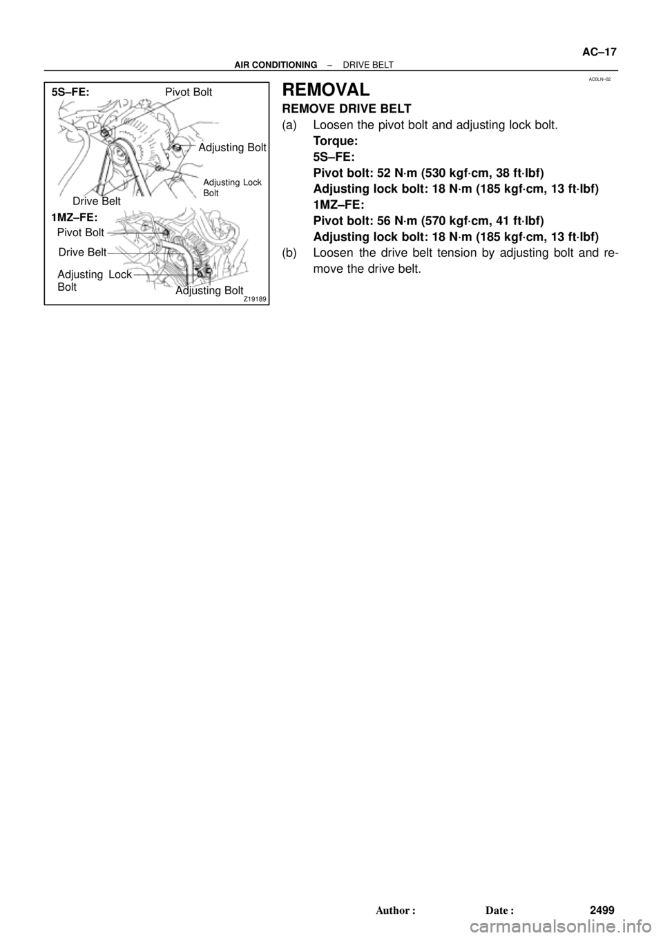
Z19189
Pivot Bolt
Adjusting Bolt
Drive Belt
Pivot Bolt
Drive Belt
Adjusting Lock
Bolt
Adjusting Bolt 5S±FE:
1MZ±FE:
Adjusting Lock
Bolt
± AIR CONDITIONINGDRIVE BELT
AC±17
2499 Author�: Date�:
REMOVAL
REMOVE DRIVE BELT
(a) Loosen the pivot bolt and adjusting lock bolt.
Torque:
5S±FE:
Pivot bolt: 52 N´m (530 kgf´cm, 38 ft´lbf)
Adjusting lock bolt: 18 N´m (185 kgf´cm, 13 ft´lbf)
1MZ±FE:
Pivot bolt: 56 N´m (570 kgf´cm, 41 ft´lbf)
Adjusting lock bolt: 18 N´m (185 kgf´cm, 13 ft´lbf)
(b) Loosen the drive belt tension by adjusting bolt and re-
move the drive belt.
Page 1540 of 4770
AC0LO±01
AC±18
± AIR CONDITIONINGDRIVE BELT
2500 Author�: Date�:
INSTALLATION
Installation is in the reverse order of removal (See page AC±17).
Page 1562 of 4770
AC0M5±02
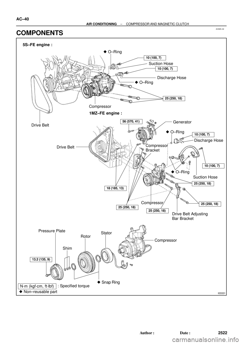
I03331
5S±FE engine :
Drive BeltCompressor� O±Ring
Suction Hose
Discharge Hose
10 (100, 7)
10 (100, 7)
� O±Ring
25 (250, 18)
1MZ±FE engine :
� O±Ring
Drive Belt
Drive Belt Adjusting
Bar BracketGenerator
Discharge Hose
10 (100, 7)
10 (100, 7)
25 (250, 18)
Compressor
25 (250, 18)
25 (250, 18)
ShimSuction Hose � O±Ring
25 (250, 18)
56 (570, 41)
18 (185, 13)
13.2 (135, 9)
Rotor Pressure Plate
: Specified torque
N´m (kgf´cm, ft´lbf)Stator
Compressor
� Snap Ring
� Non±reusable part
Compressor
Bracket AC±40
± AIR CONDITIONINGCOMPRESSOR AND MAGNETIC CLUTCH
2522 Author�: Date�:
COMPONENTS
Page 1563 of 4770

AC0M6±02
N20277
P19978
± AIR CONDITIONINGCOMPRESSOR AND MAGNETIC CLUTCH
AC±41
2523 Author�: Date�:
REMOVAL
1. RUN ENGINE AT IDLE SPEED WITH A/C ON FOR
APPROX.10 MINUTES
2. STOP ENGINE
3. DISCONNECT NEGATIVE (±) TERMINAL CABLE
FROM BATTERY
4. DISCHARGE REFRIGERANT FROM REFRIGERATION
SYSTEM
5. REMOVE DRIVE BELT
(See page AC±17)
6. 1MZ±FE engine models:
REMOVE SUCTION HOSE
(a) Remove the suction hose clamping bolt.
(b) Disconnect the wire harness clamp.
(c) Loosen the nut and bolts and remove the suction hose.
NOTICE:
Cap the open fittings immediately to keep moisture or dirt
out of the system.
7. 1MZ±FE engine models:
DISCONNECT DISCHARGE HOSE
Remove the bolt and disconnect the hose.
NOTICE:
Cap the open fittings immediately to keep moisture or dirt
out of the system.
8. 1MZ±FE engine models:
REMOVE GENERATOR
(a) Disconnect the generator connector.
(b) Remove the nut, and disconnect the generator wire.
(c) Disconnect the wire harness from the clip.
(d) Remove the pivot bolt, plate washer, adjusting lock bolt
and generator.
Page 1564 of 4770
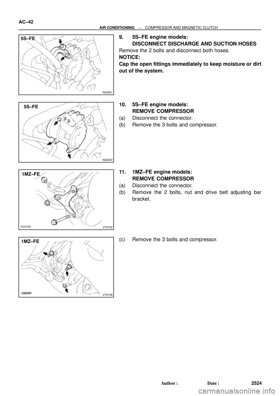
N20261
5S±FE
N20240
5S±FE
Z19152
1MZ±FE
Z19149
1MZ±FE AC±42
± AIR CONDITIONINGCOMPRESSOR AND MAGNETIC CLUTCH
2524 Author�: Date�:
9. 5S±FE engine models:
DISCONNECT DISCHARGE AND SUCTION HOSES
Remove the 2 bolts and disconnect both hoses.
NOTICE:
Cap the open fittings immediately to keep moisture or dirt
out of the system.
10. 5S±FE engine models:
REMOVE COMPRESSOR
(a) Disconnect the connector.
(b) Remove the 3 bolts and compressor.
11. 1MZ±FE engine models:
REMOVE COMPRESSOR
(a) Disconnect the connector.
(b) Remove the 2 bolts, nut and drive belt adjusting bar
bracket.
(c) Remove the 3 bolts and compressor.
Page 1569 of 4770

(B)
± AIR CONDITIONINGCOMPRESSOR AND MAGNETIC CLUTCH
AC±47
2529 Author�: Date�:
INSTALLATION
1. 5S±FE engine models:
INSTALL COMPRESSOR
(a) Install the compressor with 3 bolts.")
AC0M9±02
N20259
(A)
(B)
± AIR CONDITIONINGCOMPRESSOR AND MAGNETIC CLUTCH
AC±47
2529 Author�: Date�:
INSTALLATION
1. 5S±FE engine models:
INSTALL COMPRESSOR
(a) Install the compressor with 3 bolts.
Torque: 25 N´m (250 kgf´cm, 18 ft´lbf)
(b) Connect the connector.
2. 1MZ±FE engine models:
INSTALL COMPRESSOR
(a) Install the compressor with 3 bolts.
Torque: 25 N´m (250 kgf´cm, 18 ft´lbf)
(b) Install the drive belt adjusting bar bracket with 2 bolts and
nut.
Torque:
Bolt (A): 25 N´m (250 kgf´cm, 18 ft´lbf)
Bolt (B): 18 N´m (185 kgf´cm, 13 ft´lbf)
Nut: 25 N´m (250 kgf´cm, 18 ft´lbf)
(c) Connect the connector.
3. 5S±FE engine models:
CONNECT DISCHARGE AND SUCTION HOSE
Connect the both hoses with the 2 bolts.
Torque: 10 N´m (100 kgf´cm, 7 ft´lbf)
NOTICE:
Hoses should be connected immediately after the caps
have been removed.
HINT:
Lubricate 2 new O±rings with compressor oil and install the
tubes.
4. 1MZ±FE engine models:
INSTALL GENERATOR
(a) Mount generator on the generator bracket with the pivot
bolt and adjusting lock bolt. Do not tighten the bolts yet.
(b) Connect the generator connector.
(c) Connect the generator wire with the nut.