Page 1570 of 4770

AC±48
± AIR CONDITIONINGCOMPRESSOR AND MAGNETIC CLUTCH
2530 Author�: Date�:
5. 1MZ±FE engine models:
CONNECT DISCHARGE HOSE
Connect the discharge hose with the bolt.
Torque: 10 N´m (100 kgf´cm, 7 ft´lbf)
NOTICE:
Hoses should be connected immediately after the caps
have been removed.
HINT:
Lubricate a new O±ring with compressor oil and install the tube.
6. INSTALL SUCTION HOSE
(a) Install the suction hose and tighten the bolt and nut.
Torque:
Piping joint: 32 N´m (330 kgf´cm, 24 ft´lbf)
Block joint: 10 N´m (100 kgf´cm, 7 ft´lbf)
HINT:
Lubricate 2 new O±rings with compressor oil and install the
hose.
(b) Install the suction hose clamping bolt.
(c) Connect the wire harness clamp.
7. INSTALL AND CHECK DRIVE BELT
(See page AC±18, AC±16)
8. CONNECT NEGATIVE (±) TERMINAL CABLE TO BAT-
TERY
9. EVACUATE AIR FROM REFRIGERATION SYSTEM
AND CHARGE SYSTEM WITH REFRIGERANT
Specified amount: 800 ± 50 g (28.22 ± 1.76 oz.)
10. INSPECT FOR LEAKAGE OF REFRIGERANT
Using a gas leak detector, check for leakage of refrigerant.
If there is leakage, check the tightening torque at the joints.
11. INSPECT A/C OPERATION
Page 1962 of 4770
BO0KU±01
± BODYSRS AIRBAG
BO±3
2351 Author�: Date�:
SRS AIRBAG
PRECAUTION
The CAMRY is equipped with SRS (Supplemental Restraint System) such as the driver airbag, front passen-
ger airbag, side airbag and seat belt pretensioner. Failure to carry out service operation in the correct se-
quence could cause the SRS to unexpectedly deploy during servicing, possibly leading to a serious acci-
dent. Before servicing (including removal or installation of parts, inspection or replacement), be sure to read
the precautionary notices in the RS section.
Page 1970 of 4770
BO0L2±01
H01975
Door Lock
Cylinder
Outside Handle Front Door Belt Moulding
Door Glass
Door FrameFront Door Upper Moulding
Outside
Rear View
Mirror
Door Glass
Run
5.5 (55, 49 in.´lbf)
5.5 (55, 49 in.´lbf)
5.0 (50, 43 in.´lbf)�
Door Lock
23 (230, 17)
Window Regulator
8.0 (80, 69 in.´lbf)
Door Hinge
X6
7.5 (75, 66 in.´lbf)
Regulator
Motor
X3
31 (310, 22)
26 (260, 19)
8.0 (80, 71 in.´lbf)
30 (300, 22)
31 (310, 22)
Door
Check
Door Hinge
26 (260, 19)
Speaker
Power Window Switch Rear Lower
FrameFront Lower
FrameFront Window Upper
Garnish
Inside Handle Bezel
3.5 (35, 31 in.´lbf)
Driver's Side:
Regulator
Motor
Ptdt
N´m (kgf´cm, ft´lbf) : Specified torqueInside Handle
Door Trim
� Precoated part Door Lock StrikerService Hole Cover
± BODYFRONT DOOR
BO±11
2359 Author�: Date�:
FRONT DOOR
COMPONENTS
Page 1972 of 4770
N20970
(a)
(b)(b)
N21004
Clip
H01729
: 7 rivets
: clip
: clip
: clip
± BODYFRONT DOOR
BO±13
2361 Author�: Date�:
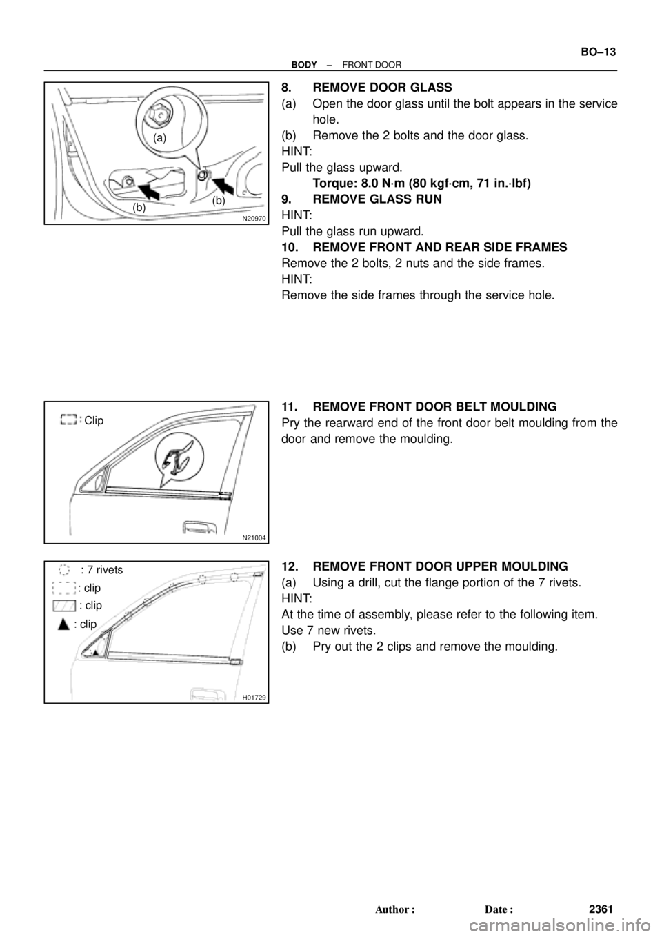
8. REMOVE DOOR GLASS
(a) Open the door glass until the bolt appears in the service
hole.
(b) Remove the 2 bolts and the door glass.
HINT:
Pull the glass upward.
Torque: 8.0 N´m (80 kgf´cm, 71 in.´lbf)
9. REMOVE GLASS RUN
HINT:
Pull the glass run upward.
10. REMOVE FRONT AND REAR SIDE FRAMES
Remove the 2 bolts, 2 nuts and the side frames.
HINT:
Remove the side frames through the service hole.
11. REMOVE FRONT DOOR BELT MOULDING
Pry the rearward end of the front door belt moulding from the
door and remove the moulding.
12. REMOVE FRONT DOOR UPPER MOULDING
(a) Using a drill, cut the flange portion of the 7 rivets.
HINT:
At the time of assembly, please refer to the following item.
Use 7 new rivets.
(b) Pry out the 2 clips and remove the moulding.
Page 1976 of 4770
BO0L6±01
H01733
Door LockRear Door Upper
Moulding
Door Belt Moulding
Door Glass
Outside handle
Door Glass Run
Door Lock
Door Lock Striker
Rear Side Frame
Rear Door WeatherstripWindow Regulator
Inside Handle BezelInside HandleWindow
Regulator
Motor Child Protector
Lock Lever Cover
Snap Ring
Regulator
Handle Plate Door Trim Service Hole Cover Power Window
Switch Cover Door HingeDoor Hinge
Door Check w/o Power Door
Lock:
w/o Power Window:
: Specified torque
N´m (kgf´cm, ft´lbf)
3.5 (35, 31 in.´lbf)
5.5 (55, 49 in.´lbf)
5.5 (55, 49 in.´lbf)
23 (230, 17)
7.0 (70, 61 in.´lbf)
Door Lock Control Link
Door Lock Remote
Control Link
5.0 (50, 43 in.´lbf)
8.0 (80, 71 in.´lbf)
26 (260, 19)
8.0 (80, 71 in.´lbf)
30 (300, 22)
26 (260, 19)
± BODYREAR DOOR
BO±17
2365 Author�: Date�:
REAR DOOR
COMPONENTS
Page 1978 of 4770
N20974
(b)(b)
(a)
N21008
Clip
H01743
: 7 rivets
: clips
: clips
: clips
± BODYREAR DOOR
BO±19
2367 Author�: Date�:
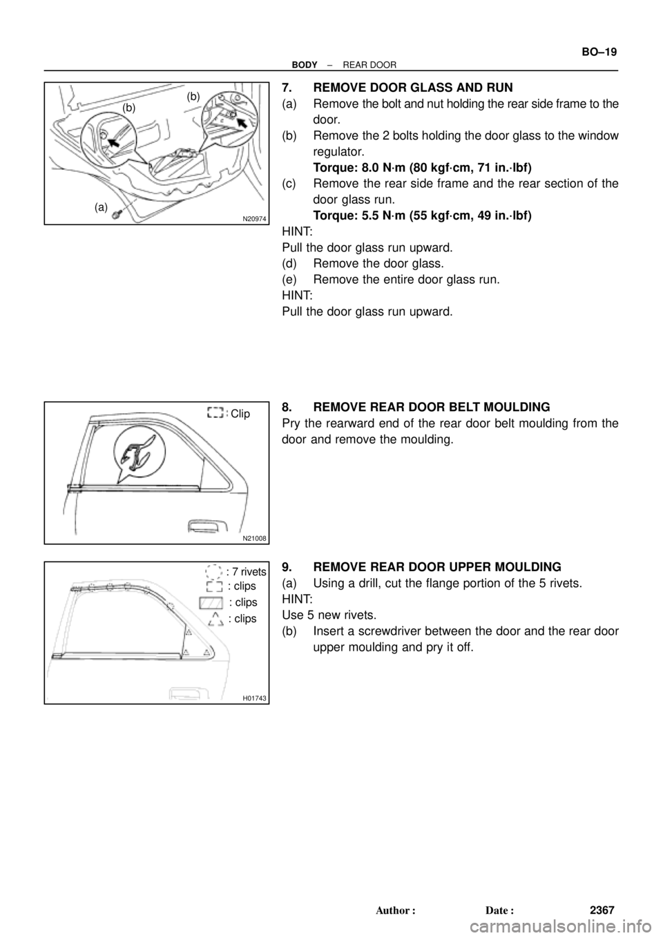
7. REMOVE DOOR GLASS AND RUN
(a) Remove the bolt and nut holding the rear side frame to the
door.
(b) Remove the 2 bolts holding the door glass to the window
regulator.
Torque: 8.0 N´m (80 kgf´cm, 71 in.´lbf)
(c) Remove the rear side frame and the rear section of the
door glass run.
Torque: 5.5 N´m (55 kgf´cm, 49 in.´lbf)
HINT:
Pull the door glass run upward.
(d) Remove the door glass.
(e) Remove the entire door glass run.
HINT:
Pull the door glass run upward.
8. REMOVE REAR DOOR BELT MOULDING
Pry the rearward end of the rear door belt moulding from the
door and remove the moulding.
9. REMOVE REAR DOOR UPPER MOULDING
(a) Using a drill, cut the flange portion of the 5 rivets.
HINT:
Use 5 new rivets.
(b) Insert a screwdriver between the door and the rear door
upper moulding and pry it off.
Page 2008 of 4770
BO0LR±01
N20948
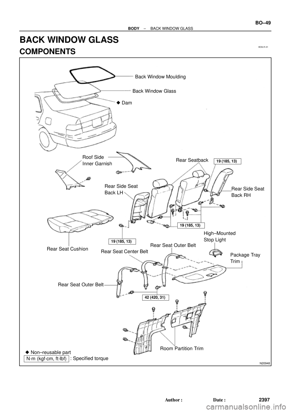
Back Window Moulding
Back Window Glass
� Dam
Roof Side
Inner GarnishRear Seatback
19 (185, 13)
42 (420, 31)
Rear Side Seat
Back RH Rear Side Seat
Back LH
Rear Seat Cushion
19 (185, 13)
19 (185, 13)
Rear Seat Center BeltRear Seat Outer BeltHigh±Mounted
Stop Light
Package Tray
Trim
Rear Seat Outer Belt
Room Partition Trim
� Non±reusable part
N´m (kgf´cm, ft´lbf): Specified torque
± BODYBACK WINDOW GLASS
BO±49
2397 Author�: Date�:
BACK WINDOW GLASS
COMPONENTS
Page 2009 of 4770

BO0LS±01
N21020
3 Clips
1 Clip
N22588
N21021
4 Clips
N21121
N20985
BO±50
± BODYBACK WINDOW GLASS
2398 Author�: Date�:
REMOVAL
1. REMOVE REAR SEAT CUSHION AND SEATBACKS
2. REMOVE ROOF SIDE INNER GARNISHES
(a) Remove the clips.
(b) Pull the garnish to remove it.
3. REMOVE HIGH±MOUNTED STOP LIGHT
(a) Push on the both side of the cover to release the claws by
your hand and remove the cover as shown in the illustra-
tion.
(b) Remove the 2 bolts and stop light, then disconnect the
connector.
4. REMOVE PACKAGE TRAY TRIM
(a) Remove the bolts holding the rear seat belt lower side to
the body.
(b) Remove the seat belts with seat belt hole covers from the
package trim.
(c) Remove the trim by pulling forward.
5. REMOVE ROOM PARTITION TRIMS
Remove the 6 clips and room partition trims.
6. REMOVE THESE PARTS
(a) Assist grips.
(b) Rear side of roof headlining.
7. DISCONNECT DEFOGGER WIRE CONNECTORS
8. REMOVE BACK WINDOW MOULDING
Using a knife, cut off the moulding as shown.
NOTICE:
Do not damage the body with the knife.
9. REMOVE BACK WINDOW GLASS
Remove the glass in the same way as windshield.
(See page BO±43)


5.5 (55, 49 in")