Page 4119 of 4770
SF07G±03
S04591
S04590
± SFI (1MZ±FE)FUEL PRESSURE REGULATOR
SF±19
1518 Author�: Date�:
REMOVAL
1. REMOVE FUEL PUMP ASSEMBLY FROM FUEL TANK
(See page SF±12)
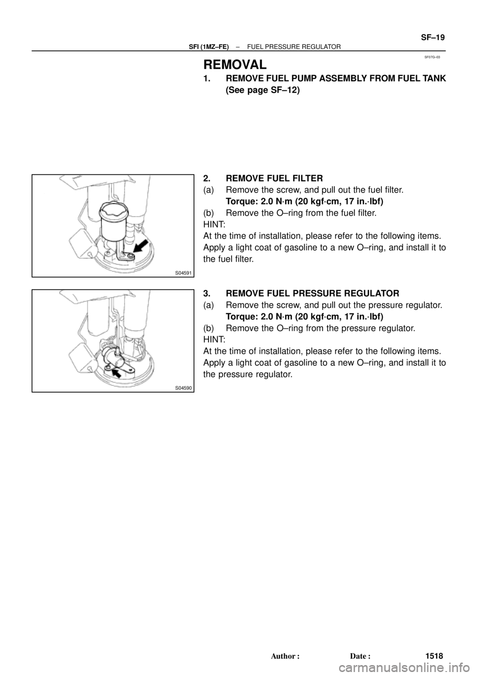
2. REMOVE FUEL FILTER
(a) Remove the screw, and pull out the fuel filter.
Torque: 2.0 N´m (20 kgf´cm, 17 in.´lbf)
(b) Remove the O±ring from the fuel filter.
HINT:
At the time of installation, please refer to the following items.
Apply a light coat of gasoline to a new O±ring, and install it to
the fuel filter.
3. REMOVE FUEL PRESSURE REGULATOR
(a) Remove the screw, and pull out the pressure regulator.
Torque: 2.0 N´m (20 kgf´cm, 17 in.´lbf)
(b) Remove the O±ring from the pressure regulator.
HINT:
At the time of installation, please refer to the following items.
Apply a light coat of gasoline to a new O±ring, and install it to
the pressure regulator.
Page 4123 of 4770
SF07K±04
S04505
S04498
S06086
Fuel Hose
Clamp
S05352
± SFI (1MZ±FE)INJECTOR
SF±23
1522 Author�: Date�:
REMOVAL
1. REMOVE AIR CLEANER HOSE
2. REMOVE AIR INTAKE CHAMBER ASSEMBLY
(See page EM±32)
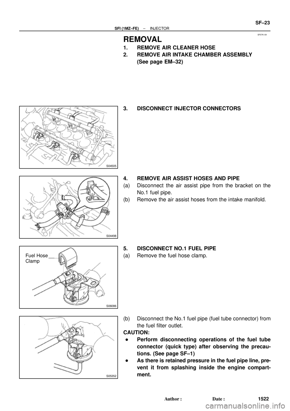
3. DISCONNECT INJECTOR CONNECTORS
4. REMOVE AIR ASSIST HOSES AND PIPE
(a) Disconnect the air assist pipe from the bracket on the
No.1 fuel pipe.
(b) Remove the air assist hoses from the intake manifold.
5. DISCONNECT NO.1 FUEL PIPE
(a) Remove the fuel hose clamp.
(b) Disconnect the No.1 fuel pipe (fuel tube connector) from
the fuel filter outlet.
CAUTION:
�Perform disconnecting operations of the fuel tube
connector (quick type) after observing the precau-
tions. (See page SF±1)
�As there is retained pressure in the fuel pipe line, pre-
vent it from splashing inside the engine compart-
ment.
Page 4126 of 4770
SST (Hose)
O±Ring
SST
(Clamp)
Vinyl Tube
Vinyl Tube
O±Ring
SST (Union)
SST (Hose)
SST
(Clamp)
California A/T
Except California A/T
S05358
TOYOTA
Hand±Held Tester SF±26
± SFI (1M")
B01914
SST (Union)SST (Hose)
O±Ring
SST
(Clamp)
Vinyl Tube
Vinyl Tube
O±Ring
SST (Union)
SST (Hose)
SST
(Clamp)
California A/T
Except California A/T
S05358
TOYOTA
Hand±Held Tester SF±26
± SFI (1MZ±FE)INJECTOR
1525 Author�: Date�:
(c) Install the grommet and O±Ring to the injector.
(d) Connect SST (union and hose) to the injector, and hold
the injector and union with SST (clamp).
SST 09268±41047
(e) Put the injector into a graduated cylinder.
HINT:
Install a suitable vinyl hose onto the injector to prevent gasoline
from splashing out.
(f) Connect a TOYOTA hand±held tester to the DLC3.
(g) Turn the ignition switch ON and push the TOYOTA hand±
held tester main switch ON.
NOTICE:
Do not start the engine.
(h) Select the ACTIVE TEST mode on the TOYOTA hand±
held tester.
(i) Please refer to the TOYOTA hand±held tester operator's
manual for further details.
(j) If you have no TOYOTA hand±held tester, connect the
positive (+) and negative (±) leads from the battery to the
fuel pump connector. (See page SF±6)
Page 4127 of 4770

BatterySST
(Wire)
B00628
California A/TExcept
California A/T
± SFI (1MZ±FE)INJECTOR
SF±27
1526 Author�: Date�:
(k) Connect SST (wire)")
B01913
California A/T
Except California A/TBatterySST
(Wire)
BatterySST
(Wire)
B00628
California A/TExcept
California A/T
± SFI (1MZ±FE)INJECTOR
SF±27
1526 Author�: Date�:
(k) Connect SST (wire) to the injector and battery for 15 se-
conds, and measure the injection volume with a gra-
duated cylinder. Test each injector 2 or 3 times.
SST 09842±30070
Volume:
60 ± 73 cm
3 (3.4 ± 4.5 cu in.) per 15 sec.
Difference between each injector:
13 cm
3 (0.8 cu in.) or less
If the injection volume is not as specified, replace the injector.
2. INSPECT LEAKAGE
(a) In the condition above, disconnect the test probes of SST
(wire) from the battery and check the fuel leakage from
the injector.
SST 09842±30070
Fuel drop: 1 drop or less per 12 minutes
(b) Turn the ignition switch OFF.
(c) Disconnect the negative (±) terminal cable from the bat-
tery.
(d) Remove the SST and fuel tube connector.
SST 09268±41047, 09842±30070
CAUTION:
�Perform disconnecting operations of the fuel tube
connector (quick type) after observing the precau-
tions. (See page SF±1)
�As there is retained pressure in the fuel pipe line, pre-
vent it from splashing inside the engine compart-
ment.
(e) Disconnect the TOYOTA hand±held tester from the
DLC3.
Page 4129 of 4770
INJECTOR
SF±29
1528 Author�: Date�:
(g) Apply a light coat of spindle oil or gasoline on the place
where a intake manifold touc")
B01021
S04728
Rotate
Outward
B01020
S06525
Align
S05351
± SFI (1MZ±FE)INJECTOR
SF±29
1528 Author�: Date�:
(g) Apply a light coat of spindle oil or gasoline on the place
where a intake manifold touches an O±ring of the injector.
(h) Place the delivery pipes and fuel pipe together with the 6
injectors in position on the intake manifold.
(i) Temporarily install the 4 bolts holding the delivery pipes
to the intake manifold.
(j) Temporarily install the bolt holding the No.1 fuel pipe to
the intake manifold.
(k) Check that the injectors rotate smoothly.
HINT:
If injectors do not rotate smoothly, the probable cause is incor-
rect installation of O±rings. Replace the O±rings.
(l) Position the injector connector outward.
(m) Tighten the 4 bolts holding the delivery pipes to the intake
manifold.
Torque: 10 N´m (100 kgf´cm, 7 ft´lbf)
(n) Tighten the bolt holding the No.1 fuel pipe to the intake
manifold.
Torque: 19.5 N´m (200 kgf´cm, 14 ft´lbf)
2. CONNECT NO.1 FUEL PIPE
(a) Align the alignment marks (white paint) on the No.1 fuel
pipe.
(b) Connect the No.1 fuel pipe (fuel tube connector) to the
fuel filter.
CAUTION:
Perform connecting operations of the fuel tube connector
(quick type) after observing the precaution.
(See page SF±1)
Page 4131 of 4770

Before installing the heated oxygen sensor,
twist the sensor wire counterclockwise
3 and 1/2 turns. HINT:
After installing the heated oxygen sen")
SF07N±03
B06469
Heated Oxygen Sensor (Bank 1 Sensor 2)
Before installing the heated oxygen sensor,
twist the sensor wire counterclockwise
3 and 1/2 turns. HINT:
After installing the heated oxygen sensor,
check that the sensor wire is not twisted,
if it is twisted, remove the heated oxygen
sensor and reinstall it. �
Location of Fuel Tank Cushion
No.1 Fuel Tank
Protector
Fuel Tank Vent
Tube Set Plate
Fuel Pump
Fuel Outlet Tube
Fuel Inlet Pipe Fuel Inlet Pipe ShieldFuel Tank Cap
Fuel Inlet Pipe Protector
Heated Oxygen Sensor
(Bank 1 Sensor 2)Heat Insulator
Fuel Tank Band
Center Exhaust Pipe � Gasket� Gasket � Gasket
� Non±reusable part
N´m (kgf´cm, ft´lbf): Specified torque
39 (400, 29)
44 (450, 33)
56 (570, 41)
56 (570, 41)
x 8
�
� Gasket
Fuel TankFuel Inlet Hose
Charcoal
Canister
EVAP Line Hose
Vent Line Hose
± SFI (1MZ±FE)FUEL TANK AND LINE
SF±31
1530 Author�: Date�:
FUEL TANK AND LINE
COMPONENTS
CAUTION:
�Always use new gaskets when replacing the fuel tank or component parts.
�Apply the proper torque to all parts tightened.
Page 4132 of 4770
SF07O±03
BO0919
Crack Leakage
Deformation
Z10162
SSTUse SST
28 N´m
(285 kgf´cm, 21 ft´lbf)
Fulcrum
Length
30 cm
(11.81 in.)
SST: 09631±22020
FU0041
PipeHose
Clip 2 ± 7 mm (0.08 ± 0.28 in.)
0 ± 3 mm (0 ± 0.12 in.)
SF±32
± SFI (1MZ±FE)FUEL TANK AND LINE
1531 Author�: Date�:
INSPECTION
INSPECT FUEL TANK AND LINE
(a) Check the fuel lines for cracks or leakage, and all connec-
tions for deformation.
(b) Check the fuel tank vapor vent system hoses and connec-
tions for looseness, sharp bends or damage.
(c) Check the fuel tank for deformation, cracks, fuel leakage
or tank band looseness.
(d) Check the filler neck for damage or fuel leakage.
(e) Hose and pipe connections are as shown in the illustra-
tion.
If a problem is found, repair or replace the parts as necessary.
Page 4530 of 4770

Toyota Supports ASE CertificationPage 1 of 1
EG002±00
Title:
DIAGNOSTIC TROUBLE CODE P1133
Models:
'97 ± '99 Camry: 1MZ±FE CA Spec.
Technical Service
BULLETIN
February 25, 2000
TSB Revision Notice:
The information updated in this TSB is red
and underlined.
Under certain driving conditions, some 1MZ±FE equipped 1997 ± 1999 Camry California
Emission specification vehicles can exhibit a M.I.L. ªONº DTC P1133. An improved
Air/Fuel Ratio Sensor has been developed to correct this condition.
�1997 ± 1999 Camry (1MZ±FE) with California Emission Specification.
MODEL YEARENGINESTARTING VIN
1999 Camry1MZ±FE4T1BF2#K * XU088001
4T1BF2#K * XU933227
PREVIOUS PART NUMBERCURRENT PART NUMBERPART NAME
89467±4102089467±41021Sensor, Air/Fuel
�Should a M.I.L. ªONº condition with DTC P1133 be encountered, perform diagnostic
procedures as described in the Repair Manual.
�If the problem source cannot be identified after checking all affected areas according
to the Repair Manual, the cause may be an Air/Fuel Ratio Sensor malfunction. In this
case, replace the Air/Fuel Ratio Sensor with the current part number listed above.
�If the Exhaust Manifold threads are damaged by removal of the sensor, they can be
repaired by the proper use of a M18 x 1.5 tap.
OP CODEDESCRIPTIONTIMEOPNT1T2
895131R & R Air/Fuel Ratio Sensor0.389467±410209999
Applicable Warranty*:
This repair is covered under the Toyota Basic Warranty. This warranty is in effect for
36 months or 36,000 miles, whichever occurs first, from the vehicle's in±service date.
Coverage is extended to 36 months or 50,000 miles, whichever occurs first, in the
states of California and Massachusetts due to state emissions warranty legislation.
NOTE:
Please enter the DTC in the condition/Cause/Remedy section when applying for
warranty reimbursement.
* Warranty application is limited to correction of a problem based upon a customer's specific complaint.
ENGINE
Introduction
Applicable
Vehicles
Production
Change
Information
Parts
Information
Repair
Procedure
Warranty
Information

Fulcrum
Length
30 cm
(11.81 in.)
SST: 09631±22020
FU0041
PipeHose
Clip 2 ± 7 mm (0.08 ± 0.28 in.)
0 ±")