Page 4038 of 4770
SFI SYSTEM
1437 Author�:")
Z11336
California
Except CaliforniaGrommetInsulator O±Ring
InjectorO±Ring
O±Ring
Grommet
InjectorInsulator
S04583
Pull
S05040
Vinyl Bag
S05382
Retainer
SF±4
± SFI (5S±FE)SFI SYSTEM
1437 Author�: Date�:
(e) Install the injector to the delivery pipe and cylinder head,
as shown in the illustration.
Before installing the injector, must apply spindle oil or gas-
oline on the place where a delivery pipe or an intake man-
ifold touches an O±ring of the injector.
(f) Observe these precautions when disconnecting the fuel
tube connector (quick type):
(1) Check if there is any dirt like mud on the pipe and
around the connector before disconnecting them
and clean the dirt away.
(2) Be sure to disconnect with hands.
(3) When the connector and the pipe are stuck, pinch
the retainer between the hands, push and pull the
connector to free to disconnect and pull it out. Do
not use any tool at this time.
(4) Inspect if there is any dirt or the likes on the seal sur-
face of the disconnected pipe and clean it away.
(5) Prevent the disconnected pipe and connector from
damaging and mixing foreign objects by covering
them with a vinyl bag.
(g) Observe these precautions when connecting the fuel
tube connector (quick type):
(1) Do not reuse the retainer removed from the pipe.
(2) Must use hands without using tools when to remove
the retainer from the pipe.
(3) Check if there is any damage or foreign objects on
the connected part of the pipe.
Page 4041 of 4770
GasketSST (Union Bolt)
SST
(Gauge)
Gasket
S04508
Ohmmeter
4
5
± SFI (5S±FE)FUEL PUMP
SF±7
1440 Author�: Date�:
(d) Install the fuel inlet hose and SST (pres")
S05328
Fuel Inlet
Hose
Gasket
SST (Union)GasketSST (Union Bolt)
SST
(Gauge)
Gasket
S04508
Ohmmeter
4
5
± SFI (5S±FE)FUEL PUMP
SF±7
1440 Author�: Date�:
(d) Install the fuel inlet hose and SST (pressure gauge) to the
fuel filter outlet with the 3 gaskets and SST (union bolt).
SST 09268±45014 (09268±41190, 90405±06167)
Torque: 29 N´m (300 kgf´cm, 21 ft´lbf)
(e) Wipe off any splattered gasoline.
(f) Reconnect the negative (±) terminal cable to the battery.
(g) Connect a TOYOTA hand±held tester to the DLC3.
(See step 1 in check fuel pump operation (a) to (e))
(h) Measure the fuel pressure.
Fuel pressure:
301 ± 347 kPa (3.1 ± 3.5 kgf/cm
2, 44 ± 50 psi)
If pressure is high, replace the fuel pressure regulator.
If pressure is low, check the fuel hoses, fuel hose connections,
fuel pump, fuel filter and fuel pressure regulator.
(i) Disconnect the TOYOTA hand±held tester from the
DLC3.
(j) Start the engine.
(k) Measure the fuel pressure at idle.
Fuel pressure:
301 ± 347 kPa (3.1 ± 3.5 kgf/cm
2, 44 ± 50 psi)
(l) Stop the engine.
(m) Check that the fuel pressure remains as specified for 5
minutes after the engine has stopped.
Fuel pressure:
147 kPa (1.5 kgf/cm
2, 21 psi) or more
If pressure is not as specified, check the fuel pump, pressure
regulator and/or injectors.
(n) After checking fuel pressure, disconnect the negative (±)
terminal cable from the battery and carefully remove the
SST to prevent gasoline from splashing.
SST 09268±45014
(o) Reconnect the fuel inlet hose with 2 new gaskets and the
union bolt.
Torque: 29 N´m (300 kgf´cm, 21 ft´lbf)
(p) Reconnect the negative (±) terminal cable to the battery.
(q) Check for fuel leaks. (See page SF±1)
3. REMOVE REAR SEAT CUSHION
4. REMOVE FLOOR SERVICE HOLE COVER
5. DISCONNECT FUEL PUMP & SENDER GAUGE CON-
NECTOR
6. INSPECT FUEL PUMP RESISTANCE
Using an ohmmeter, measure the resistance between terminals
4 and 5.
Resistance: 0.2 ± 3.0 W at 20°C (68°F)
If the resistance is not as specified, replace the fuel pump.
Page 4045 of 4770
FUEL PUMP
SF±11
1444 Author�: Date�:
REMOVAL
CAUTION:
Do not smoke or work near an open flame when working on
the fuel pump.
1. REMOVE REAR SEAT CUSHI")
SF0D9±03
S04583
S04592
Vinyl Bag
± SFI (5S±FE)FUEL PUMP
SF±11
1444 Author�: Date�:
REMOVAL
CAUTION:
Do not smoke or work near an open flame when working on
the fuel pump.
1. REMOVE REAR SEAT CUSHION
2. REMOVE FLOOR SERVICE HOLE COVER
(a) Take out the floor carpet.
(b) Remove the service hole cover.
HINT:
At the time of installation, please refer to the following items.
Check for fuel leakage.
3. DISCONNECT FUEL PUMP & SENDER GAUGE CON-
NECTOR
4. REMOVE NO.1 FUEL TANK PROTECTOR
Remove the 2 bolts and No.1 fuel tank protector.
Torque: 4 N´m (40 kgf´cm, 35 in.´lbf)
5. DISCONNECT FUEL TUBE (FUEL TUBE CONNEC-
TOR)
CAUTION:
�Perform disconnecting and connecting operations of
the fuel tube connector (quick type) after observing
the precautions.
�As there is retained pressure in the fuel pipe line, pre-
vent it from splashing inside the vehicle compart-
ment.
6. REMOVE FUEL PUMP ASSEMBLY FROM FUEL TANK
(a) Remove the 6 bolts and fuel tank vent tube set plate.
Torque: 4 N´m (40 kgf´cm, 35 in.´lbf)
(b) Pull out the fuel pump assembly.
(c) Remove the gasket from the pump assembly.
NOTICE:
�Do not damage the fuel pump filter.
�Be careful that the arm of the sender gauge should
not bent.
HINT:
At the time of installation, please refer to the following items.
Install a new gasket to the pump assembly.
Page 4046 of 4770
(3)
(2) Type B SF±12
± SFI (5S±FE)FUEL PUMP
1445 Author�: Date�:
DISASSEMBLY
1. DISCONNECT FUEL PUMP CONNECTOR")
SF0DA±02
S06028
Type B
S04603Pull Type A
S06033
PushA Type B
S06050
Type B
S06030
(1)(3)
(2) Type B SF±12
± SFI (5S±FE)FUEL PUMP
1445 Author�: Date�:
DISASSEMBLY
1. DISCONNECT FUEL PUMP CONNECTOR
2. Type B:
DISCONNECT GROUND PLATE
3. Type B:
DISCONNECT FUEL SENDER GAUGE CONNECTOR
4. Type A:
REMOVE FUEL PUMP FROM FUEL PUMP BRACKET
(a) Pull off the lower side of the fuel pump from the pump
bracket.
(b) Disconnect the fuel hose from the fuel pump, and remove
the fuel pump.
(c) Remove the rubber cushion from the fuel pump.
5. Type B:
REMOVE FUEL SENDER GAUGE.
Push down the portion of A with a finger, and push up the send-
er gauge.
NOTICE:
Be careful that the arm of the sender gauge should not
bent.
6. Type B:
REMOVE FUEL FILTER
(a) Remove the screw, and pull out the fuel filter.
(b) Remove the O±ring from the fuel filter.
HINT:
At the time of installation, please refer to the following items. Ap-
ply a light coat of gasoline to a new O±ring, and install it to the
fuel filter.
Torque: 2.0 N´m (20 kgf´cm, 17 in.´lbf)
7. Type B:
REMOVE FUEL PUMP FLANGE
Using a screwdriver, remove the snap fit portion in the order of
1, 2 and 3 as shown in the illustration.
HINT:
At the time of installation, please refer to the following items. Ap-
ply a light coat of gasoline to a new O±ring of the fuel pump.
Page 4052 of 4770
SF0DE±03
S04591
S04590
SF±18
± SFI (5S±FE)FUEL PRESSURE REGULATOR
1451 Author�: Date�:
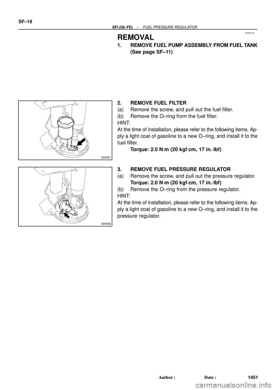
REMOVAL
1. REMOVE FUEL PUMP ASSEMBLY FROM FUEL TANK
(See page SF±11)
2. REMOVE FUEL FILTER
(a) Remove the screw, and pull out the fuel filter.
(b) Remove the O±ring from the fuel filter.
HINT:
At the time of installation, please refer to the following items. Ap-
ply a light coat of gasoline to a new O±ring, and install it to the
fuel filter.
Torque: 2.0 N´m (20 kgf´cm, 17 in.´lbf)
3. REMOVE FUEL PRESSURE REGULATOR
(a) Remove the screw, and pull out the pressure regulator.
Torque: 2.0 N´m (20 kgf´cm, 17 in.´lbf)
(b) Remove the O±ring from the pressure regulator.
HINT:
At the time of installation, please refer to the following items. Ap-
ply a light coat of gasoline to a new O±ring, and install it to the
pressure regulator.
Page 4057 of 4770
Union Bolt
SST (Union)
Injector Fuel Filter
(On Vehicle)SST
(Clamp)
SST
(Union)
S05522
S05524
Union Bolt
Gasket SST (Union)
SST (Hose)
P01078
SST
(Clamp) O±Ring
Vinyl
Tube")
SF0DJ±03
S05525
SST (Hose)Union Bolt
SST (Union)
Injector Fuel Filter
(On Vehicle)SST
(Clamp)
SST
(Union)
S05522
S05524
Union Bolt
Gasket SST (Union)
SST (Hose)
P01078
SST
(Clamp) O±Ring
Vinyl
Tube SST (Union)SST (Hose)
S05331
± SFI (5S±FE)INJECTOR
SF±23
1456 Author�: Date�:
INSPECTION
1. INSPECT INJECTOR INJECTION
CAUTION:
Keep injector clean of sparks during the test.
(a) Remove the union bolt and 2 gaskets, and disconnect the
fuel inlet hose from the fuel filter outlet.
(b) Connect SST (union and hose) to the fuel filter outlet with
the 2 gaskets and union bolts.
SST 09268±41047 (90405±09015)
Torque: 29 N´m (300 kgf´cm, 21 ft´lbf)
(c) Install the grommet and O±ring to the injector.
(d) Connect SST (union and hose) to the injector, and hold
the injector and union with SST (clamp).
SST 09268±41047 (09268±41100, 09268±41110)
(e) Put the injector into the graduated cylinder.
CAUTION:
Install a suitable vinyl hose onto the injector to prevent
gasoline from splashing out.
(f) Connect a TOYOTA hand±held tester to the DLC3.
(g) Connect the battery negative (±) cable to the battery.
(h) Turn the ignition switch ON and push the TOYOTA hand±
held tester main switch ON.
NOTICE:
Do not start the engine.
(i) Select the ACTIVE TEST mode on the TOYOTA hand±
held tester.
(j) Please refer to the TOYOTA hand±held tester operator's
manual for further details.
Page 4061 of 4770

Before installing the heated oxygen sensor,
twist the sensor wire counterclockwise
3 and 1/2 turns. HINT:
After installing the heated oxygen sen")
SF0DL±03
B06469
Heated Oxygen Sensor (Bank 1 Sensor 2)
Before installing the heated oxygen sensor,
twist the sensor wire counterclockwise
3 and 1/2 turns. HINT:
After installing the heated oxygen sensor,
check that the sensor wire is not twisted,
if it is twisted, remove the heated oxygen
sensor and reinstall it. �Location of Fuel Tank Cushion
No.1 Fuel Tank
Protector
Fuel Tank Vent
Tube Set Plate
Fuel Pump
Fuel Outlet Tube
Fuel Inlet Pipe Fuel Inlet Pipe Shield
Fuel Tank Cap
Fuel Inlet Pipe Protector
Heated Oxygen Sensor
(Bank 1 Sensor 2)Heat Insulator
Fuel Tank Band
Center Exhaust Pipe � Gasket� Gasket � Gasket
� Non±reusable part
N´m (kgf´cm, ft´lbf): Specified torque
39 (400, 29)
44 (450, 33)
56 (570, 41)
56 (570, 41)
x 8
�
� Gasket
Fuel TankFuel Inlet Hose
Charcoal
Canister
EVAP Line Hose Vent Line Hose
± SFI (5S±FE)FUEL TANK AND LINE
SF±27
1460 Author�: Date�:
FUEL TANK AND LINE
COMPONENTS
CAUTION:
�Always use new gaskets when replacing the fuel tank or component parts.
�Apply the proper torque to all parts tightened
Page 4062 of 4770
SF0DM±03
BO0919
Crack
Leakage
Deformation
Z10162
Use SST
28 N´m
(285 kgf´cm, 21ft´lbf)
Fulcrum
Length
30 cm
(11.81 in.) SST
SST: 09631±22020
FU0041
2 ± 7 mm (0.08 ± 0.28 in.)
0 ± 3 mm (0 ± 0.12 in.) Pipe
Clip Hose
SF±28
± SFI (5S±FE)FUEL TANK AND LINE
1461 Author�: Date�:
INSPECTION
INSPECT FUEL TANK AND LINE
(a) Check the fuel lines for cracks or leakage, and all connec-
tions for deformation.
(b) Check the fuel tank vapor vent system hoses and connec-
tions for looseness, sharp bends or damage.
(c) Check the fuel tank for deformation, cracks, fuel leakage
or tank band looseness.
(d) Check the filler neck for damage or fuel leakage.
(e) Hose and pipe connections are as shown in the illustra-
tion.
If a problem is found, repair or replace the parts as necessary.

Fulcrum
Length
30 cm
(11.81 in.) SST
SST: 09631±22020
FU0041
2 ± 7 mm (0.08 ± 0.28 in.)
0 ± 3 mm (0 ± 0.")