Page 2692 of 4770

DI±272
± DIAGNOSTICSENGINE (1MZ±FE)
507 Author�: Date�:
DTC P0171 System too Lean (Fuel Trim)
(Except California Spec.)
DTC P0172 System too Rich (Fuel Trim)
(Except California Spec.)
CIRCUIT DESCRIPTION
Fuel trim refers to the feedback compensation value compared against the basic injection time. Fuel trim
includes short±term fuel trim and long±term fuel trim.
Short±term fuel trim is the short±term fuel compensation used to maintain the air±fuel ratio at its ideal
theoretical value. The signal from the heated oxygen sensor indicates whether the air±fuel ratio is RICH or
LEAN compared to the ideal theoretical value, triggering a reduction in fuel volume if the air±fuel ratio is rich,
and an increase in fuel volume if it is lean.
Long±term fuel trim is overall fuel compensation carried out long±term to compensate for continual deviation
of the short±term fuel trim from the central value due to individual engine differences, wear over time and
changes in the usage environment.
If both the short±term fuel trim and long±term fuel trim are LEAN or RICH beyond a certain value, it is
detected as a malfunction and the MIL lights up.
DTC No.DTC Detecting ConditionTrouble Area
P0171
When air fuel ratio feedback is stable after engine warming up,
fuel trim is considerably in error on RICH side
(2 trip detection logic)
�Air intake (hose loose)
�Fuel line pressure
�Injector blockage
�Heated oxygen sensors (bank 1, 2 sensor 1) malfunction
�Mass air flow meter
�Engine coolant temp. sensor
�Gas leakage on exhaust system
P0172
When air fuel ratio feedback is stable after engine warming up,
fuel trim is considerably in error on LEAN side
(2 trip detection logic)
�Fuel line pressure
�Injector leak, blockage
�Heated oxygen sensors (bank 1, 2 sensor 1) malfunction
�Mass air flow meter
�Engine coolant temp. sensor
�Gas leakage on exhaust system
HINT:
�When DTC P0171 is recorded, the actual air±fuel ratio is on the LEAN side. When DTC P0172 is re-
corded, the actual air±fuel ratio is on the RICH side.
�If the vehicle runs out of fuel, the air±fuel ratio is LEAN and DTC P0171 is recorded. The MIL then
comes on.
�If the total of the short±term fuel trim value and long±term fuel trim value is within + 35 % (80°C (176°F)
or more), the system is functioning normally.
INSPECTION PROCEDURE
HINT:
Read freeze frame data using TOYOTA hand±held tester or OBD II scan tool. Because freeze frame records
the engine conditions when the malfunction is detected, when troubleshooting it is useful for determining
whether the vehicle was running or stopped, the engine warmed up or not, the air±fuel ratio lean or rich, etc.
at the time of the malfunction.
DI4DR±01
Page 2693 of 4770
± DIAGNOSTICSENGINE (1MZ±FE)
DI±273
508 Author�: Date�:
1 Check air induction system (See page SF±1).
NG Repair or replace.
OK
2 Check injector injection (See page SF±21).
NG Replace injector.
OK
3 Check mass air flow meter and engine coolant temp. sensor
(See pages SF±35 and SF±63).
NG Repair or replace.
OK
4 Check for spark and ignition (See page IG±1).
NG Repair or replace.
OK
5 Check fuel pressure (See page SF±6).
NG Check and repair fuel pump, pressure regulator,
fuel pipe line and filter.
OK
Page 2696 of 4770

DI±276
± DIAGNOSTICSENGINE (1MZ±FE)
511 Author�: Date�:
DTC P0300 Random/Multiple Cylinder Misfire Detected
DTC P0301 Cylinder 1 Misfire Detected
DTC P0302 Cylinder 2 Misfire Detected
DTC P0303 Cylinder 3 Misfire Detected
DTC P0304 Cylinder 4 Misfire Detected
DTC P0305 Cylinder 5 Misfire Detected
DTC P0306 Cylinder 6 Misfire Detected
CIRCUIT DESCRIPTION
Misfire: The ECM uses the crankshaft position sensor and camshaft position sensor to monitor changes in
the crankshaft rotation for each cylinder.
The ECM counts the number of times the engine speed change rate indicates that misfire has occurred.
When the misfire rate equals or exceeds the count indicating that the engine condition has deteriorated, the
MIL lights up.
If the misfire rate is high enough and the driving conditions will cause catalyst overheating, the MIL blinks
when misfiring occurs.
DTC No.DTC Detecting ConditionTrouble Area
P0300Misfiring of random cylinders is detected during any
particular 200 or 1,000 revolutions�Ignition system
�Injector
�Fuel line pressure
P0301
P0302
P0303For any particular 200 revolutions for engine, misfiring is de-
tected which can cause catalyst overheating
(This causes MIL to blink)
�EGR
�Compression pressure
�Valve clearance not to specification
�Valve timing
�Mass air flow meterP0303
P0304
P0305
P0306For any particular 1,000 revolutions of engine, misfiring is de-
tected which causes a deterioration in emission
(2 trip detection logic)
�Mass air flow meter
�Engine coolant temp. sensor
�Open or short in engine wire
�Connector connection
�ECM
DI07S±07
Page 2699 of 4770

A00221P25779
P23917
± DIAGNOSTICSENGINE (1MZ±FE)
DI±279
514 Author�: Date�:
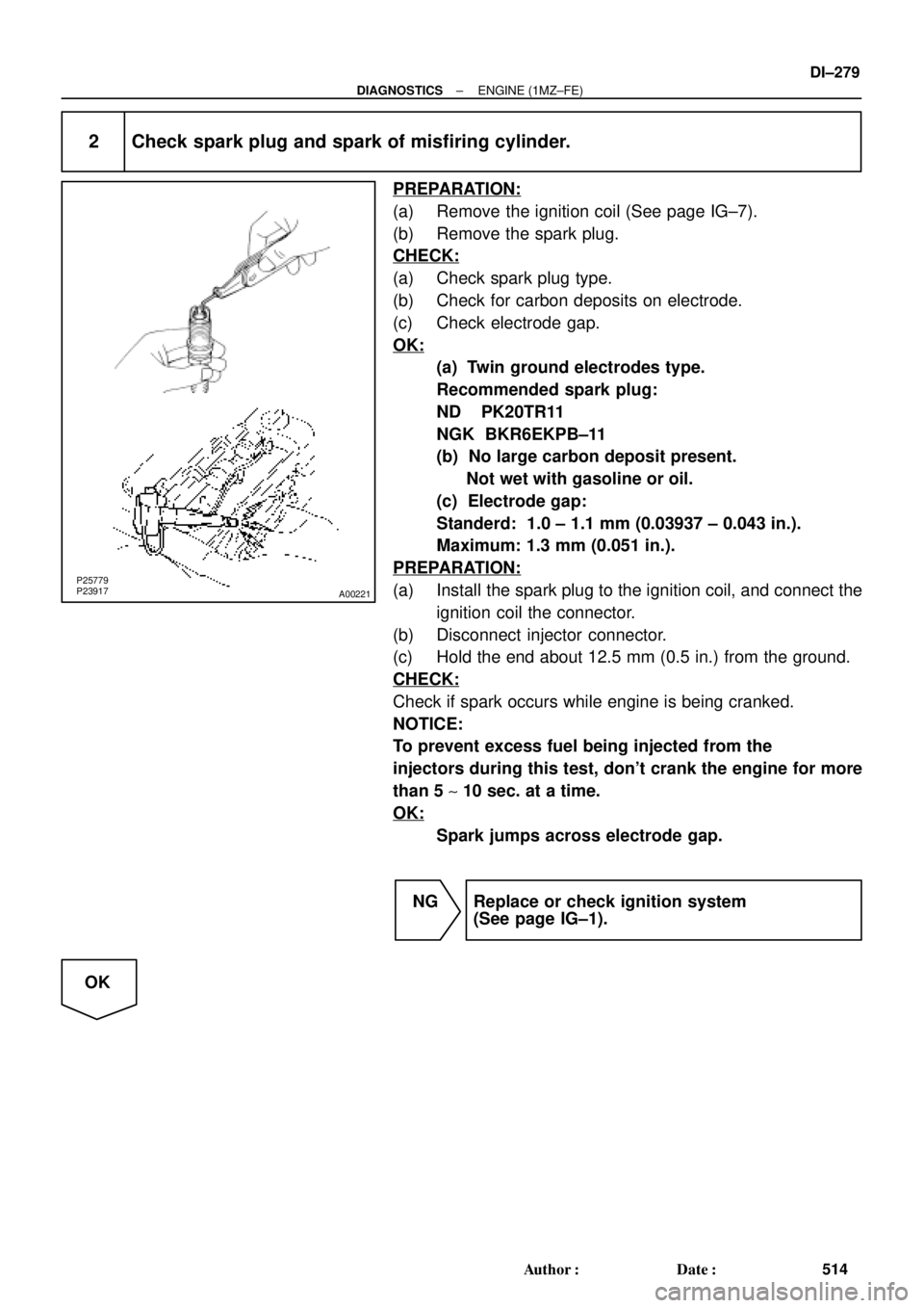
2 Check spark plug and spark of misfiring cylinder.
PREPARATION:
(a) Remove the ignition coil (See page IG±7).
(b) Remove the spark plug.
CHECK:
(a) Check spark plug type.
(b) Check for carbon deposits on electrode.
(c) Check electrode gap.
OK:
(a) Twin ground electrodes type.
Recommended spark plug:
ND PK20TR11
NGK BKR6EKPB±11
(b) No large carbon deposit present.
Not wet with gasoline or oil.
(c) Electrode gap:
Standerd: 1.0 ± 1.1 mm (0.03937 ± 0.043 in.).
Maximum: 1.3 mm (0.051 in.).
PREPARATION:
(a) Install the spark plug to the ignition coil, and connect the
ignition coil the connector.
(b) Disconnect injector connector.
(c) Hold the end about 12.5 mm (0.5 in.) from the ground.
CHECK:
Check if spark occurs while engine is being cranked.
NOTICE:
To prevent excess fuel being injected from the
injectors during this test, don't crank the engine for more
than 5 ~ 10 sec. at a time.
OK:
Spark jumps across electrode gap.
NG Replace or check ignition system
(See page IG±1).
OK
Page 2701 of 4770
± DIAGNOSTICSENGINE (1MZ±FE)
DI±281
516 Author�: Date�:
4 Check resistance of injector of misfiring cylinder (See page SF±21).
NG Replace injector.
OK
Check for open and short in harness and
connector between injector and ECM
(See page IN±31).
5 Check fuel pressure (See page SF±6).
NG Check and repair fuel pump, fuel pipe line and
filter (See page SF±1).
OK
6 Check injector injection (See page SF±25).
NG Replace injector.
OK
7 Check EGR system (See page EC±11).
NG Replace EGR system.
OK
Page 2731 of 4770

A01652
ECM
Vapor Pressure
Sensor
VSV for Vapor
Pressure Sensor VSV
for EVAP
Charcoal Canister
Fuel Tank (1)
(2)
(3) fig. 1
(6)
(4)
(5) (7)
Fuel Tank Over Fill
Check Valve
(8)
(9)
± DIAGNOSTICSENGINE (1MZ±FE)
DI±311
546 Author�: Date�:
DTC P0440 Evaporative Emission Control System
Malfunction
CIRCUIT DESCRIPTION
The vapor pressure sensor and VSV for vapor pressure sensor are used to detect abnormalities in the evap-
orative emission control system.
The ECM decides whether there is an abnormality in the evaporative emission control system based on the
vapor pressure sensor signal.
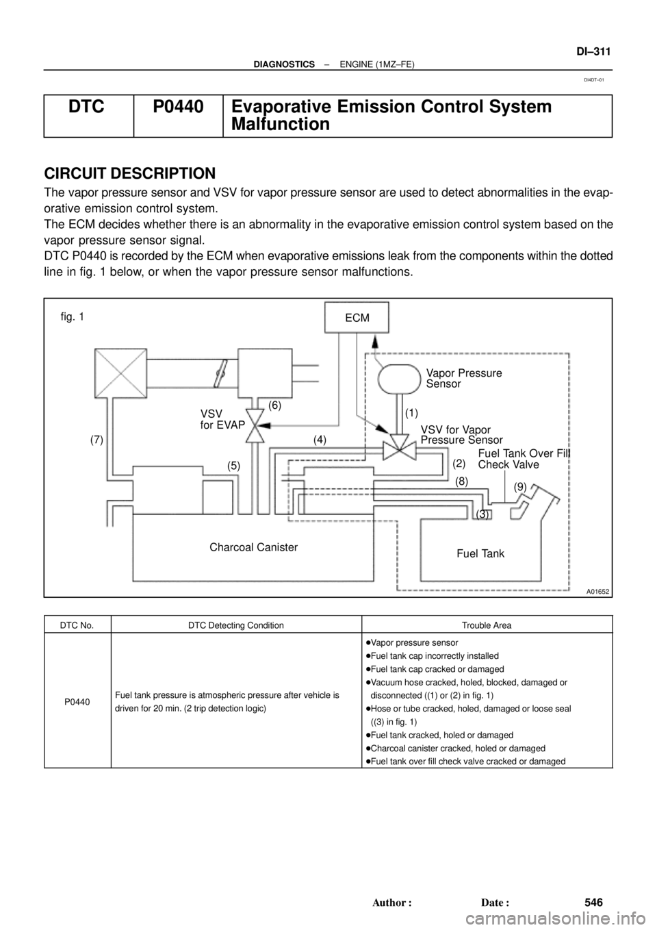
DTC P0440 is recorded by the ECM when evaporative emissions leak from the components within the dotted
line in fig. 1 below, or when the vapor pressure sensor malfunctions.
DTC No.DTC Detecting ConditionTrouble Area
P0440Fuel tank pressure is atmospheric pressure after vehicle is
driven for 20 min. (2 trip detection logic)
�Vapor pressure sensor
�Fuel tank cap incorrectly installed
�Fuel tank cap cracked or damaged
�Vacuum hose cracked, holed, blocked, damaged or
disconnected ((1) or (2) in fig. 1)
�Hose or tube cracked, holed, damaged or loose seal
((3) in fig. 1)
�Fuel tank cracked, holed or damaged
�Charcoal canister cracked, holed or damaged
�Fuel tank over fill check valve cracked or damaged
DI4DT±01
Page 2738 of 4770
A01654
ECM
Vapor Pressure
Sensor
VSV for Vapor
Pressure Sensor
Fuel Tank Charcoal Canister VSV
for EVAP(1)
(2)
(3) (4)
(5) fig. 1
(6)
(7)
(8)
(9)Fuel Tank Over
Fill Check Valve DI±318
± DIAGNOSTICSENGINE (1MZ±FE)
553 Author�: Date�:
DTC P0441 Evaporative Emission Control System
Incorrect Purge Flow
DTC P0446 Evaporative Emission Control System Vent
Control Malfunction
CIRCUIT DESCRIPTION
The vapor pressure sensor and VSV for vapor pressure sensor are used to detect abnormalities in the evap-
orative emission control system.
The ECM decides whether there is an abnormality in the evaporative emission control system based on the
vapor pressure sensor signal.
DTCs P0441 and P0446 are recorded by the ECM when evaporative emissions leak from the components
within the dotted line in fig. 1 below, or when there is a malfunction in either the VSV for EVAP, the VSV for
vapor pressure sensor, or in the vapor pressure sensor itself.
DI080±07
Page 2763 of 4770
± DIAGNOSTICSENGINE (1MZ±FE)
DI±343
578 Author�: Date�:
3 Check for open and short in harness and connector between ECM and A/F sen-
sors (bank 1, 2 sensor 1) (See page IN±31).
NG Repair or replace harness or connector.
OK
4 Check resistance of A/F sensor heater (See page SF±68).
NG Replace A/F sensor.
OK
5 Check air induction system (See page SF±1).
NG Repair or replace.
OK
6 Check EGR system (See page EC±11).
NG Replace EGR system.
OK
7 Check fuel pressure (See page SF±21).
NG Check and repair fuel pump, fuel pipe line and
filter (See page SF±1).
OK