Page 2633 of 4770

± DIAGNOSTICSENGINE (1MZ±FE)
DI±213
448 Author�: Date�:
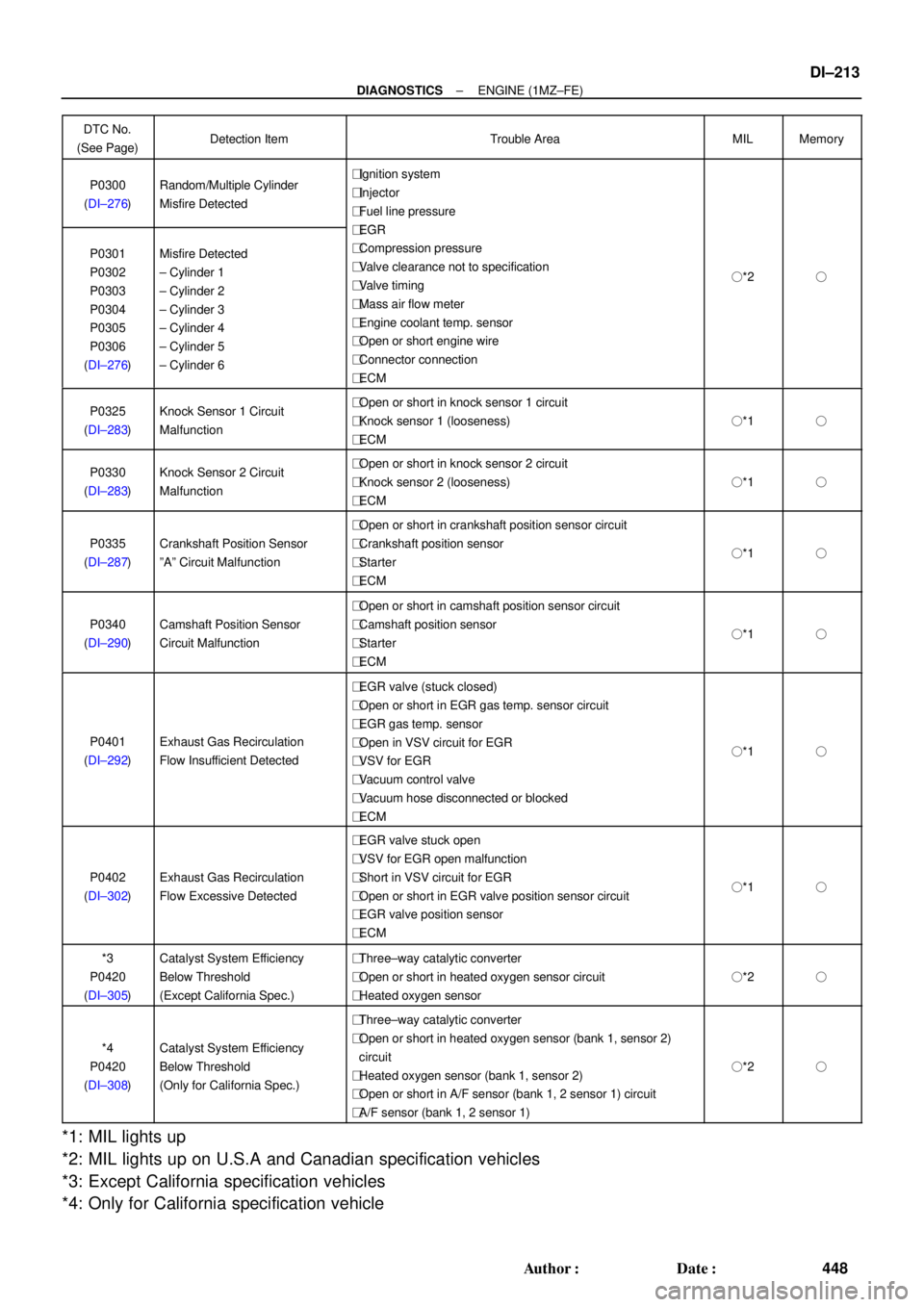
DTC No.
(See Page)Detection ItemTrouble AreaMILMemory
P0300
(DI±276)Random/Multiple Cylinder
Misfire Detected�Ignition system
�Injector
�Fuel line pressure
EGR
P0301
P0302
P0303
P0304
P0305
P0306
(DI±276)Misfire Detected
± Cylinder 1
± Cylinder 2
± Cylinder 3
± Cylinder 4
± Cylinder 5
± Cylinder 6
�EGR
�Compression pressure
�Valve clearance not to specification
�Valve timing
�Mass air flow meter
�Engine coolant temp. sensor
�Open or short engine wire
�Connector connection
�ECM
�*2�
P0325
(DI±283)Knock Sensor 1 Circuit
Malfunction�Open or short in knock sensor 1 circuit
�Knock sensor 1 (looseness)
�ECM
�*1�
P0330
(DI±283)Knock Sensor 2 Circuit
Malfunction�Open or short in knock sensor 2 circuit
�Knock sensor 2 (looseness)
�ECM
�*1�
P0335
(DI±287)Crankshaft Position Sensor
ºAº Circuit Malfunction
�Open or short in crankshaft position sensor circuit
�Crankshaft position sensor
�Starter
�ECM
�*1�
P0340
(DI±290)Camshaft Position Sensor
Circuit Malfunction
�Open or short in camshaft position sensor circuit
�Camshaft position sensor
�Starter
�ECM
�*1�
P0401
(DI±292)Exhaust Gas Recirculation
Flow Insufficient Detected
�EGR valve (stuck closed)
�Open or short in EGR gas temp. sensor circuit
�EGR gas temp. sensor
�Open in VSV circuit for EGR
�VSV for EGR
�Vacuum control valve
�Vacuum hose disconnected or blocked
�ECM
�*1�
P0402
(DI±302)Exhaust Gas Recirculation
Flow Excessive Detected
�EGR valve stuck open
�VSV for EGR open malfunction
�Short in VSV circuit for EGR
�Open or short in EGR valve position sensor circuit
�EGR valve position sensor
�ECM
�*1�
*3
P0420
(DI±305)Catalyst System Efficiency
Below Threshold
(Except California Spec.)�Three±way catalytic converter
�Open or short in heated oxygen sensor circuit
�Heated oxygen sensor
�*2�
*4
P0420
(DI±308)Catalyst System Efficiency
Below Threshold
(Only for California Spec.)
�Three±way catalytic converter
�Open or short in heated oxygen sensor (bank 1, sensor 2)
circuit
�Heated oxygen sensor (bank 1, sensor 2)
�Open or short in A/F sensor (bank 1, 2 sensor 1) circuit
�A/F sensor (bank 1, 2 sensor 1)
�*2�
*1: MIL lights up
*2: MIL lights up on U.S.A and Canadian specification vehicles
*3: Except California specification vehicles
*4: Only for California specification vehicle
Page 2659 of 4770

P24296
ECM
Throttle Position
Sensor
VC
VTA1
E2
S05019
ECM
1
3
25 V
VC
VTA1
E2 Y
L
BR Throttle Position Sensor
E102
23
18 E10
E10
± DIAGNOSTICSENGINE (1MZ±FE)
DI±239
474 Author�: Date�:
DTC P0120 Throttle/Pedal Position Sensor/Switch ºAº
Circuit Malfunction
CIRCUIT DESCRIPTION
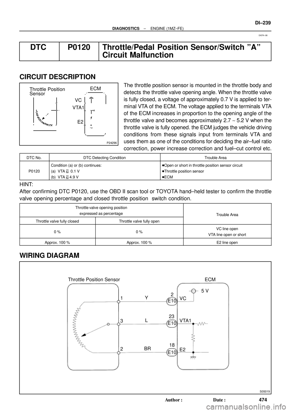
The throttle position sensor is mounted in the throttle body and
detects the throttle valve opening angle. When the throttle valve
is fully closed, a voltage of approximately 0.7 V is applied to ter-
minal VTA of the ECM. The voltage applied to the terminals VTA
of the ECM increases in proportion to the opening angle of the
throttle valve and becomes approximately 2.7 ~ 5.2 V when the
throttle valve is fully opened. the ECM judges the vehicle driving
conditions from these signals input from terminals VTA and
uses them as one of the conditions for deciding the air±fuel ratio
correction, power increase correction and fuel±cut control etc.
DTC No.DTC Detecting ConditionTrouble Area
P0120
Condition (a) or (b) continues:
(a) VTA
0.1 V
(b) VTA
4.9 V
�Open or short in throttle position sensor circuit
�Throttle position sensor
�ECM
HINT:
After confirming DTC P0120, use the OBD II scan tool or TOYOTA hand±held tester to confirm the throttle
valve opening percentage and closed throttle position switch condition.
Throttle valve opening position
expressed as percentage
Trouble Area
Throttle valve fully closedThrottle valve fully open
Trouble Area
0 %0 %VC line open
VTA line open or short
Approx. 100 %Approx. 100 %E2 line open
WIRING DIAGRAM
DI07K±06
Page 2667 of 4770
± DIAGNOSTICSENGINE (1MZ±FE)
DI±247
482 Author�: Date�:
4 Check whether misfire is occurred or not by monitoring DTC and data list.
NG Perform troubleshooting for misfire
(See page DI±351).
OK
5 Check air induction system (See page SF±1).
NG Repair or replace.
OK
6 Check EGR system (See page EC±11).
NG Replace EGR system.
OK
7 Check fuel pressure (See page SF±6).
NG Check and repair fuel pump, fuel pipe line and
filter (See page SF±1).
OK
8 Check injector injection (See page SF±25)
NG Replace injector.
OK
Page 2673 of 4770
± DIAGNOSTICSENGINE (1MZ±FE)
DI±253
488 Author�: Date�:
4 Check resistance of A/F sensor heaters (bank1, 2 sensor1) (See page SF±68).
NG Replace A/F sensor.
OK
5 Check air induction system (See page SF±1).
NG Repair or replace.
OK
6 Check EGR system (See page EC±11).
NG Replace EGR system.
OK
7 Check fuel pressure (See page SF±21).
NG Check and repair fuel pump, fuel pipe line and
filter (See page SF±1).
OK
8 Check injector injection (See page SF±25).
NG Replace injector.
OK
Page 2677 of 4770
± DIAGNOSTICSENGINE (1MZ±FE)
DI±257
492 Author�: Date�:
3 Check for open and short in harness and connector between ECM and heated
oxygen sensors (bank1, 2 sensor1) (See page IN±31).
NG Repair or replace harness or connector.
OK
4 Check air induction system (See page SF±1).
NG Repair or replace.
OK
5 Check EGR system (See page EC±11).
NG Replace EGR system.
OK
6 Check fuel pressure (See page SF±6).
NG Check and repair fuel pump, fuel pipe line and
filter (See page SF±1).
OK
Page 2681 of 4770
± DIAGNOSTICSENGINE (1MZ±FE)
DI±261
496 Author�: Date�:
5 Check EGR system (See page EC±11).
NG Replace EGR system.
OK
6 Check fuel pressure (See page SF±1).
NG Check and repair fuel pump, fuel pipe line and
filter (See page SF±1).
OK
7 Check injector injection (See page SF±25).
NG Replace injector.
OK
Replace heated oxygen sensors
(bank1, 2 sensor1).
8 Perform confirmation driving pattern (See page DI±255).
Go
Page 2687 of 4770

± DIAGNOSTICSENGINE (1MZ±FE)
DI±267
502 Author�: Date�:
DTC P0171 System too Lean (Fuel Trim)
(Only for California Spec.)
DTC P0172 System too Rich (Fuel Trim)
(Only for California Spec.)
CIRCUIT DESCRIPTION
Fuel trim refers to the feedback compensation value compared against the basic injection time. Fuel trim
includes short±term fuel trim and long±term fuel trim.
Short±term fuel trim is the short±term fuel compensation used to maintain the air±fuel ratio at its ideal
theoretical value.
The signal from the A/F sensor is approximately proportional to the existing air±fuel ratio, and ECM compar-
ing it with the ideal theoretical value, the ECM reduces fuel volume immediately if the air±fuel ratio is rich
and increases fuel volume if it is lean.
Long±term fuel trim compensates the deviation from the central value of the short±term fuel trim stored up
by each engine tolerance, and the deviation from the central value due to the passage of time and changes
of using environment.
If both the short±term fuel trim and long±term fuel trim exceed a certain value, it is detected as a malfunction
and the MIL lights up.
DTC No.DTC Detecting ConditionTrouble Area
P0171
When air fuel ratio feedback is stable after engine warming up,
fuel trim is considerably in error on RICH side
(2 trip detection logic)
�Gas leakage on exhaust system
�Air intake (hose loose)
�Fuel line pressure
�Injector blockage
�Mass air flow meter
�Engine coolant temp. sensor
�A/F sensors (bank 1, 2 sensor 1)
P0172
When air fuel ratio feedback is stable after engine warming up,
fuel trim is considerably in error on LEAN side
(2 trip detection logic)
�Gas leakage on exhaust system
�Fuel line pressure
�Injector leak, blockage
�Mass air flow meter
�Engine coolant temp. sensor
�A/F sensors (bank 1, 2 sensor 1)
DI07R±05
Page 2689 of 4770
± DIAGNOSTICSENGINE (1MZ±FE)
DI±269
504 Author�: Date�:
4 Check for spark and ignition (See page IG±1).
NG Repair or replace.
OK
5 Check fuel pressure (See page SF±21).
NG Check and repair fuel pump, pressure regulator,
fuel pipe line and filter (See page SF±1).
OK
6 Check gas leakage on exhaust system.
NG Repair or replace.
OK