SA08M±01
W03225
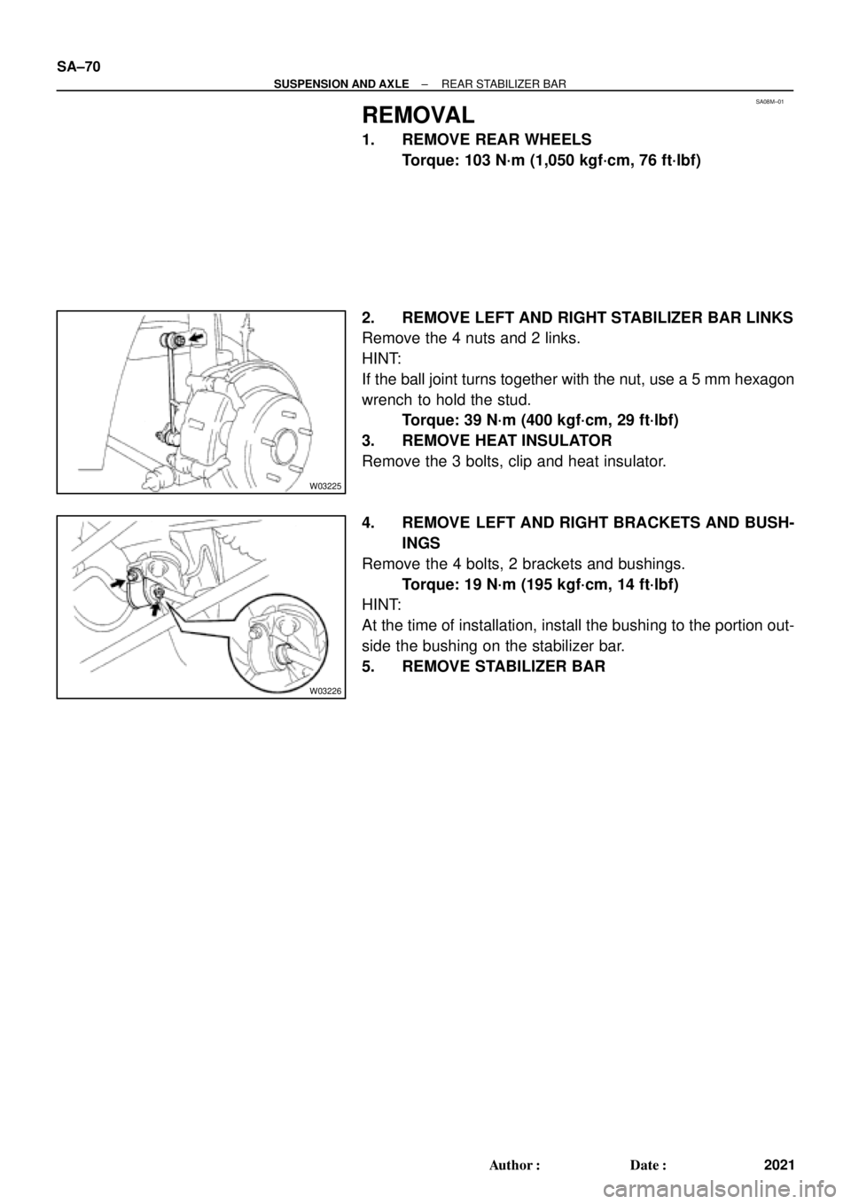
W03226
SA±70
± SUSPENSION AND AXLEREAR STABILIZER BAR
2021 Author�: Date�:
REMOVAL
1. REMOVE REAR WHEELS
Torque: 103 N´m (1,050 kgf´cm, 76 ft´lbf)
2. REMOVE LEFT AND RIGHT STABILIZER BAR LINKS
Remove the 4 nuts and 2 links.
HINT:
If the ball joint turns together with the nut, use a 5 mm hexagon
wrench to hold the stud.
Torque: 39 N´m (400 kgf´cm, 29 ft´lbf)
3. REMOVE HEAT INSULATOR
Remove the 3 bolts, clip and heat insulator.
4. REMOVE LEFT AND RIGHT BRACKETS AND BUSH-
INGS
Remove the 4 bolts, 2 brackets and bushings.
Torque: 19 N´m (195 kgf´cm, 14 ft´lbf)
HINT:
At the time of installation, install the bushing to the portion out-
side the bushing on the stabilizer bar.
5. REMOVE STABILIZER BAR
BR002±94
BRAKE VIBRATION AND/OR PULSATIONPage 6 of 6
C. Phase Match Rotor To Hub
± If rotor runout is at the maximum value or greater, (refer to appropriate repair manual)
index the rotor one lug and measure the runout again. Repeat this process, moving the
rotor one lug each time, until the position is found where the runout is at the minimum and
within the maximum value listed in the appropriate repair manual
(See Figure 6 below).
± Tighten lug nuts to the specified torque following a star sequence when installing wheel
(See Figure 7 below).
Note: DO NOT USE AIR IMPACT WRENCH.
Four Holes Five Holes
Figure 7Figure 6
BRAKE PAD CLICKING NOISE ± BR004±00 October 20, 2000
Page 2 of 4
There are two types of brake calipers: floating and fixed. Check the type of brake caliper
installed on the vehicle by removing the wheel assembly.
1. Floating Type Brake Caliper
A. Lift up or remove the brake caliper
and suspend it securely.
HINT:
Do not disconnect the flexible hose
from the brake caliper.
B. If equipped with anti±squeal
spring: Remove the anti±squeal
springs.
C. Remove the brake pads with
anti±squeal shims.
D. Remove the pad support plates
from the torque plate. Clean any
dust from the pad support plates,
torque plates and brake pads.
E. Apply a small amount of the
disc brake caliper grease
(1±2 mm thick) to both sides
of the pad support plates.
NOTE:
Do NOT apply grease to the friction
surfaces of the brake pads or the
disc rotor.
F. If the pad support plate is fixed to
the torque plate with adhesive tape,
perform the operation according to
the following flow chart.
Without removing the pad
support plate, apply a small
amount of grease to the portion
where the pad touches the
surface of the support plate.Fixed firmly in placeThere is adhesive tape, but
it is not fixed firmly in placeAdhesive tape is peeled offRemove the pad support plate,
peel off the adhesive tape and
apply a small amount of grease to
both sides of the support plate.Remove the pad support plate
and apply a small amount of
grease to both sides of the
support plate.
Check whether or not the pad support plate
and the torque plate are fixed firmly in place
with adhesive tape.
Application
Procedure
Pad Support
PlatesTorque
Plate
Apply Disc Brake Caliper Grease
Pad Support Plates
Toyota Supports ASE CertificationPage 1 of 2
ST001-01Title:
STEERING WHEEL NUT SERVICE
SPECIFICATION
Models:
All Applicable Models
Technical Service
BULLETIN
February 16, 2001
To make the steering wheel installation procedure similar for all models, the steering
wheel nut tightening torque has been standardized.
MODELMODEL YEARS
TERCELEL42, 531991 ± 1998
ECHONCP122000
PASEOEL44, 541992 ± 1997
COROLLAAE10#, ZZE1101993 ± 2001
CELICAAT180, ST18#, AT2#,
ST2#, ZZT23#1990 ± 2000
MR2SW2#, ZZW301991 ± 1995; 2000
CAMRYSXV10, 20, MCV10, 201992 ± 2000
CAMRY CNGSXV232000 ± 2001
CAMRY SOLARASXV20, MCV201999 ± 2000
AVALONMCX10, 201995 ± 2000
SUPRAJZA801993 1/2 ± 1998
RAV4SXA1#1996 ± 2000
RAV4 EVBEA111998 ± 2000
PREVIATRC10, 201991 ± 1997
SIENNAMCL101998 ± 2000
HIGHLANDERACU20, 25, MCU20, 252001
4RUNNERRN12#, 13#, VZN12#, 13#,
18#, RZN180, 1851990 ± 2000
LAND CRUISERFZ80, FZJ80, UZJ1001991 ± 2000
TRUCKRN8#, 9#, 10#, 110,
VZN85, 9#, 10#, 1101989 ± 1995
TACOMARZN140, 150, 161, 171,
19#, VZN150, 160, 170, 1951995 1/2 ± 2000
T100VCK10, 201993 ± 1998
TUNDRAVCK30, 40, UCK30, 402000
OP CODEDESCRIPTIONTIMEOPNT1T2
N/ANot Applicable to Warranty ±±±±
STEERING
Introduction
Applicable
Vehicles
Warranty
Information
Page 1 of 1Toyota Supports ASE Certification
ST002±00Title:
STEERING WHEEL NUT
Models:
'94 ± '00 Camry
Technical Service
BULLETIN
May 12, 2000
The steering wheel installation nut torque specification has been changed. Please update
the repair manuals for the applicable vehicles.
�1994 ± 2000 model year Camry
50 N m (510 kgf cm, 37 ft lbf)
OP CODEDESCRIPTIONTIMEOPNT1T2
N/ANot Applicable to Warranty ±±±±
STEERING
Introduction
Applicable
Vehicles
Warranty
Information
Toyota Supports ASE CertificationPage 1 of 2
SU001-02Title:
REAR BEARING O-RING SERVICE TIP
Models:
'97 ± '01 Camry, '00 ± '02 Avalon &
'99 ± '02 Solara
Technical Service
BULLETIN
March 1, 2002
When replacing the rear hub bearing assemblies on 1997 ± 2001 model year Camry,
2000 ± 2002 Avalon and 1999 ± 2002 Solara vehicles, replace the O±ring.
�1997 ± 2001 model year Camry vehicles.
�2000 ± 2002 model year Avalon vehicles produced before the VIN shown below.
�1999 ± 2002 model year Solara vehicles produced before the VIN shown below.
MODELSTARTING VIN
Avalon4T1BF28B#2U223623
Solara2T1##2#P#2C005335
PART NUMBERPART NAME
90301±63006O±Ring
OP CODEDESCRIPTIONTIMEOPNT1T2
N/ANot Applicable to Warranty±±±±
REMOVAL
1. Remove Rear Wheel.
Torque: 103 N�m (1,050 kgf�cm, 76 ft�lbf)
2. With Disc Brake:
Remove Brake Caliper and Disc.
A. Remove the brake caliper and disc.
Torque: 47 N�m (475 kgf�cm, 34 ft�lbf)
B. Support the brake caliper securely.
3. With Drum Brake:
Remove Brake Drum.
SUSPENSION
Introduction
Applicable
Vehicles
Production
Change
Information
Parts
Information
Warranty
Information
Repair
Procedure

index the rotor one lug an")


