Page 4031 of 4770

SS0BY±01
± SERVICE SPECIFICATIONSBODY
SS±69
232 Author�: Date�:
BODY
TORQUE SPECIFICATION
Part tightenedN´mkgf´cmft´lbf
FRONT BUMPER±±±
Front bumper cover x Body5.55549 in.´lbf
Front bumper reinforcement x Body3435025
REAR BUMPER±±±
Rear bumper cover x Body5.05043 in.´lbf
Rear bumper reinforcement x Body3435025
HOOD±±±
Hood hinge x Hood2626019
Hood lock x Body8.08071 in.´lbf
FRONT AND REAR DOOR±±±
Front door hinge x Body3131022
Rear door hinge x Body2626019
Door hinge x Door panel2626019
Door lock striker x Body2626019
Outside rear view mirror x Front door panel5.55549
Door inside handle x Door panel3.53531 in.´lbf
Door glass x Window regulator8.08071 in.´lbf
Window regulator x Door panel5.55549 in.´lbf
Door lock x Door panel5.05043 in.´lbf
Door outside handle x Door panel7.07061 in.´lbf
Door check x Body3030022
Door check x Door panel8.08071 in.´lbf
LUGGAGE COMPARTMENT DOOR AND HINGE±±±
Luggage door hinge x Luggage door8.08071 in.´lbf
Luggage door lock striker x Body5.55549 in.´lbf
Luggage door lock x Luggage door5.55549 in.´lbf
FRONT WIPER AND WASHER±±±
Wiper motor assembly x Body2424518
Wiper arm x Wiper pivot5.55549 in.´lbf
SLIDING ROOF±±±
Sliding roof assembly x Body5.55549 in.´lbf
INSTRUMENT PANEL±±±
Front passenger airbag assembly x Reinforcement2020014
Steering wheel lock nut3536026
SEAT±±±
Front Seat (Power Seat for TMC Made)±±±
Hinge cover x Seatback frame1818513
Seatback frame x Power seat adjuster1515011
Seatback frame x Side airbag assembly6.06153 in.´lbf
Front Seat (Manual Seat for TMC Made)±±±
Front seat adjuster x Body3737527
Page 4189 of 4770
RS00Y±20
H03294
Column Upper Cover
Spiral CableSteering Wheel
Steering Wheel Pad
Column Lower Cover
N´m (kgf´cm, ft´lbf) : Specified torque
7.1 (72, 63 in.´lbf)
35 (360, 26)
Steering Wheel Lower
No.2 Cover
Steering Wheel Lower
No.2 Cover
Torx Screw
RS±14
± SUPPLEMENTAL RESTRAINT SYSTEMSTEERING WHEEL PAD AND SPIRAL CABLE
2159 Author�: Date�:
STEERING WHEEL PAD AND SPIRAL CABLE
COMPONENTS
Page 4298 of 4770
R07653
SR06G±01
F01477
SR±8
± STEERINGSTEERING WHEEL
2103 Author�: Date�:
STEERING WHEEL
INSPECTION
1. CHECK STEERING WHEEL FREEPLAY
With the vehicle stopped and tires facing straight ahead, rock
the steering wheel gently back and forth with light finger pres-
sure.
Freeplay should not exceed the maximum.
Maximum freeplay: 30 mm (1.18 in.)
2. CHECK STEERING EFFORT
(a) Center the steering wheel.
(b) Remove the steering wheel pad.
(See page SR±11)
(c) Start the engine and run it at idle.
(d) Measure the steering effort in both directions.
Reference: 5.9 N´m (60 kgf´cm, 52 in.´lbf)
HINT:
Be sure to consider the tire type, pressure and contact surface
before making your diagnosis.
(e) Torque the steering wheel set nut.
Torque: 35 N´m (360 kgf´cm, 26 ft´lbf)
(f) Install the steering wheel pad.
(See page SR±16)
Page 4299 of 4770
SR06H±03
W03348
Torx ScrewSteering Wheel Pad
Steering Wheel
Torx Screw
Steering Wheel Lower
No.2 Cover
Steering Column Assembly
Intermediate Shaft Assembly
No.1 Lower Instrument Panel Combination Switch
(w/ Spiral Cable)Steering Wheel Lower
No.2 Cover
Column
Upper Cover
Lower No.2
Cover
Column Lower Cover
Lower Instrument
Finish Panel
Hood Lock Control Cable
Clip
Front Door Inside Scuff Plate
Cowl Side Trim LH Lower
Instrument Panel
35 (360, 26)
25 (260, 19)
7.1 (72, 63 in.´lbf)
35 (360, 26)
35 (360, 26)
7.1 (72, 63 in.´lbf)
N´m (kgf´cm, ft´lbf) : Specified torque
± STEERINGTILT STEERING COLUMN
SR±9
2104 Author�: Date�:
TILT STEERING COLUMN
COMPONENTS
Page 4306 of 4770
 Torque the 4 column assembly set nuts.
Torque:")
SR06M±01
W03303
Matchmarks
W02655
Mark SR±16
± STEERINGTILT STEERING COLUMN
2111 Author�: Date�:
INSTALLATION
1. INSTALL STEERING COLUMN ASSEMBLY
(a) Torque the 4 column assembly set nuts.
Torque: 25 N´m (260 kgf´cm, 19 ft´lbf)
(b) Connect the connectors.
2. INSTALL INTERMEDIATE SHAFT ASSEMBLY
Torque the bolt.
Torque: 35 N´m (360 kgf´cm, 26 ft´lbf)
3. CONNECT INTERMEDIATE SHAFT ASSEMBLY
(a) Align the matchmarks on the intermediate shaft and con-
trol valve shaft.
(b) Torque the bolt.
Torque: 35 N´m (360 kgf´cm, 26 ft´lbf)
4. INSTALL SPIRAL CABLE
(See page BE±23)
5. INSTALL COMBINATION SWITCH WITH SPIRAL
CABLE
(a) Tighten the 3 screws.
(b) Connect the airbag connector.
(c) Connect the 3 connectors.
6. INSTALL LOWER INSTRUMENT FINISH PANEL
7. INSTALL LH LOWER INSTRUMENT PANEL
Tighten the 4 bolts.
8. INSTALL No.1 LOWER INSTRUMENT PANEL
(a) Connect the hood lock control cable.
(b) Tighten the 2 screws.
9. INSTALL COWL SIDE TRIM
Install the clip.
10. INSTALL FRONT DOOR INSIDE SCUFF PLATE
11. INSTALL UPPER AND LOWER COLUMN COVERS
(a) Tighten the 3 screws.
(b) Install the lower No.2 cover to the lower cover.
12. CENTER SPIRAL CABLE
(a) Check that the front wheels are facing straight ahead.
(b) Turn the cable counterclockwise by hand until it becomes
harder to turn the cable.
(c) Then rotate the cable clockwise about 3 turns to align the
mark.
HINT:
The cable will rotate about 3 turns to either left or right of the
center.
Page 4307 of 4770
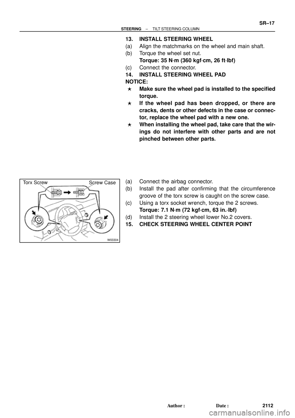
W03304
Torx Screw
Screw Case
± STEERINGTILT STEERING COLUMN
SR±17
2112 Author�: Date�:
13. INSTALL STEERING WHEEL
(a) Align the matchmarks on the wheel and main shaft.
(b) Torque the wheel set nut.
Torque: 35 N´m (360 kgf´cm, 26 ft´lbf)
(c) Connect the connector.
14. INSTALL STEERING WHEEL PAD
NOTICE:
�Make sure the wheel pad is installed to the specified
torque.
�If the wheel pad has been dropped, or there are
cracks, dents or other defects in the case or connec-
tor, replace the wheel pad with a new one.
�When installing the wheel pad, take care that the wir-
ings do not interfere with other parts and are not
pinched between other parts.
(a) Connect the airbag connector.
(b) Install the pad after confirming that the circumference
groove of the torx screw is caught on the screw case.
(c) Using a torx socket wrench, torque the 2 screws.
Torque: 7.1 N´m (72 kgf´cm, 63 in.´lbf)
(d) Install the 2 steering wheel lower No.2 covers.
15. CHECK STEERING WHEEL CENTER POINT
Page 4338 of 4770

or less
SST
W04231
Fulcrum
LengthSST SR±48
± STEERINGPOWER STEERING GEAR
2143 Author�: Date�:
18. INSTALL RH AND LH RACK BOOTS, CLAMPS AND
CLIPS
(a) Ensure that the ste")
R11669
W04223
2 mm
(0.79 in.)
or less
SST
W04231
Fulcrum
LengthSST SR±48
± STEERINGPOWER STEERING GEAR
2143 Author�: Date�:
18. INSTALL RH AND LH RACK BOOTS, CLAMPS AND
CLIPS
(a) Ensure that the steering rack hole is not clogged with
grease.
HINT:
If the hole is clogged, the pressure inside the boot will change
after it is assembled and the steering wheel is turned.
(b) Install the boot.
NOTICE:
Be careful not to damage or twist the boot.
(c) Using SST, tighten the clamp as shown in the illustration.
SST 09521±24010
19. INSTALL RH AND LH TIE ROD ENDS AND LOCK NUTS
(a) Screw the lock nut and tie rod end onto the rack end until
the matchmarks are aligned.
(b) After adjusting toe±in, torque the nut.
(See page SA±4)
Torque: 74 N´m (750 kgf´cm, 54 ft´lbf)
20. INSTALL 2 TURN PRESSURE TUBES
(a) Coat 2 new O±rings with power steering fluid and install
them to the tube.
(b) Using SST, install the tube.
SST 09633±00020
Torque: 10 N´m (102 kgf´cm, 7 ft´lbf)
HINT:
�Use a torque wrench with a fulcrum length of 250 mm
(9.84 in.).
�This torque value is effective in case that SST is parallel
to a torque wrench.
Page 4339 of 4770
 Install the gear assembly from the LH of the vehicle.
NOTICE")
SR06Y±01
W04224
SST
Fulcrum
Length
± STEERINGPOWER STEERING GEAR
SR±49
2144 Author�: Date�:
INSTALLATION
1. INSTALL PS GEAR ASSEMBLY
(a) Install the gear assembly from the LH of the vehicle.
NOTICE:
Do not damage the turn pressure tubes.
(b) Torque the 2 gear assembly set bolts and nuts.
Torque: 181 N´m (1,850 kgf´cm, 134 ft´lbf)
HINT:
Lift up the stabilizer bar and install the bolts.
2. INSTALL NO.1 FUEL TUBE PROTECTOR
Install the 2 bolts and nut.
3. CONNECT STABILIZER BAR
Torque the 4 bolts.
Torque: 19 N´m (195 kgf´cm, 14 ft´lbf)
4. CONNECT PRESSURE FEED AND RETURN TUBES
Using SST, connect the tube.
SST 09631±22020
Torque: 32 N´m (326 kgf´cm, 24 ft´lbf)
HINT:
�Use a torque wrench with a fulcrum length of 300 mm
(11.81 in.).
�This torque value is effective in case that SST is parallel
to a torque wrench.
5. CONNECT CLAMP PLATE
Torque the nut.
Torque: 10 N´m (100 kgf´cm, 7 ft´lbf)
6. CONNECT INTERMEDIATE SHAFT ASSEMBLY
(See page SR±16)
7. CONNECT RH AND LH TIE ROD ENDS
(See page SA±10)
8. POSITION FRONT WHEELS FACING STRAIGHT
AHEAD
HINT:
Do it with the front of the vehicle jacked up.
9. CENTER SPIRAL CABLE
(See page SR±16)
10. INSTALL STEERING WHEEL
(a) Install the wheel at straight±ahead position.
(b) Temporarily tighten the wheel set nut.
(c) Connect the connector.
11. BLEED POWER STEERING SYSTEM
(See page SR±4)
12. CHECK STEERING WHEEL CENTER POINT
 : Specified torque
7.1 (72, 63 in.´lbf)
35 (360, 26)
Steering Wheel Lower")