Page 2268 of 4770

2. REMOVE REAR DISC BRAKE ASSEMBLY")
BR0B9±03
W03265
R00309
BR3948
R00310
BR±46
± BRAKEPARKING BRAKE
2069 Author�: Date�:
DISASSEMBLY
1. REMOVE REAR WHEEL
Torque: 103 N´m (1.050 kgf´cm, 76 ft´lbf)
2. REMOVE REAR DISC BRAKE ASSEMBLY
(a) Remove the 2 mounting bolts and remove the disc brake
assembly.
Torque: 47 N´m (475 kgf´cm, 34 ft´lbf)
(b) Suspend the disc brake securely. Ensure that the hose is
not stretched.
3. REMOVE DISC
Release the parking brake lever and remove the disc.
HINT:
If the disc cannot be removed easily, turn the shoe adjuster until
the wheel turns freely.
4. REMOVE SHOE RETURN SPRINGS
Using needle±nose pliers, remove the shoe return springs.
5. REMOVE FRONT SHOE ADJUSTER AND TENSION
SPRING
(a) Slide out the front shoe and remove the shoe adjuster.
(b) Remove the shoe strut with the spring.
(c) Remove the shoe hold±down spring cups, spring and pin.
(d) Disconnect the tension spring and remove the front shoe.
6. REMOVE REAR SHOE
(a) Slide out the rear shoe.
(b) Remove the tension spring from the rear shoe.
(c) Remove the shoe hold±down spring cups, spring and pin.
(d) Using needle±nose pliers, disconnect the parking brake
cable from the parking brake shoe lever.
Page 2343 of 4770
CL03J±01
Q10017
Flywheel
Clutch Disc
19 (195, 14)
47 (480, 35)
Clutch Coverx 6
Release Bearing and Hub
Release Fork5S±FE :
Release Fork
39 (400, 29)
5S±FE :
Clutch Disc
N´m (kgf´cm, ft´lbf) : Specified torqueBoot
± CLUTCHCLUTCH UNIT
CL±17
1796 Author�: Date�:
CLUTCH UNIT
COMPONENTS
Page 2347 of 4770
CL03M±02
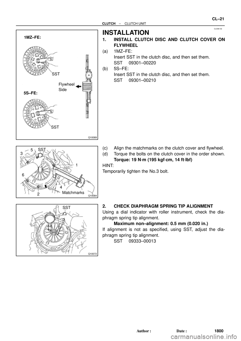
Q10089
1MZ±FE:
5S±FE:SST
Flywheel
Side
SST
Q10084
SST
1
Matchmarks
4
2
6
35
Q10072
SST
± CLUTCHCLUTCH UNIT
CL±21
1800 Author�: Date�:
INSTALLATION
1. INSTALL CLUTCH DISC AND CLUTCH COVER ON
FLYWHEEL
(a) 1MZ±FE:
Insert SST in the clutch disc, and then set them.
SST 09301±00220
(b) 5S±FE:
Insert SST in the clutch disc, and then set them.
SST 09301±00210
(c) Align the matchmarks on the clutch cover and flywheel.
(d) Torque the bolts on the clutch cover in the order shown.
Torque: 19 N´m (195 kgf´cm, 14 ft´lbf)
HINT:
Temporarily tighten the No.3 bolt.
2. CHECK DIAPHRAGM SPRING TIP ALIGNMENT
Using a dial indicator with roller instrument, check the dia-
phragm spring tip alignment.
Maximum non±alignment: 0.5 mm (0.020 in.)
If alignment is not as specified, using SST, adjust the dia-
phragm spring tip alignment.
SST 09333±00013
Page 2817 of 4770

DI±397
632 Author�: Date�:
6. MECHANICAL SYSTEM TESTS
(a) Measure the stall speed.
The object of this test is to check the overall performance of the transax")
± DIAGNOSTICSAUTOMATIC TRANSAXLE (A140E)
DI±397
632 Author�: Date�:
6. MECHANICAL SYSTEM TESTS
(a) Measure the stall speed.
The object of this test is to check the overall performance of the transaxle and engine by measuring
the stall speeds in the D and R positions.
NOTICE:
�Do the test at normal operating fluid temperature 50 ± 80 °C (122 ± 176 °F).
�Do not continuously run this test for longer than 5 seconds.
�To ensure safety, conduct this test in a wide, clear level area which provides good traction.
�The stall test should always be carried out in pairs. One technician should observe the condi-
tions of wheels or wheel stoppers outside the vehicle while the other is doing the test.
(1) Chock the 4 wheels.
(2) Connect an OBD II scan tool or TOYOTA hand±held tester to DLC3.
(3) Fully apply the parking brake.
(4) Keep your left foot depressing firmly on the brake pedal.
(5) Start the engine.
(6) Shift into the D position. Press all the way down on the accelerator pedal with your right foot.
Quickly read the stall speed at this time.
Stall speed: 2,450 ± 150 rpm
(7) Do the same test in R position.
Stall speed: 2,450 ± 150 rpm
Evaluation:
ProblemPossible cause
(a) Stall speed low in D and R positions
�Engine output may be insufficient
�Stator one±way clutch is operating properly
�HINT: If more than 600 rpm below the specified value, the torque
converter clutch could be faulty.
(b) Stall speed high in D position
�Line pressure too low
�Forward clutch slipping
�No.2 one±way clutch not operating properly
�O/D clutch slipping
(c) Stall speed high in R position
�Line pressure too low
�Direct clutch slipping
�1st & reverse brake slipping
�O/D clutch slipping
(d) Stall speed high in D and R positions
�Line pressure too low
�Improper fluid level
�O/D one±way clutch not operating properly
Page 2865 of 4770

DI±445
680 Author�: Date�:
(f) Inspect and adjust the shift lever position.
When shifting the shift")
Q00199
Q04604
Q04700
Bolt Neutral Basic Line
Groove
Bolt
± DIAGNOSTICSAUTOMATIC TRANSAXLE (A541E)
DI±445
680 Author�: Date�:
(f) Inspect and adjust the shift lever position.
When shifting the shift lever from the N position to other
positions, check that the lever can be shifted smoothly
and accurately to each position and that the position indi-
cator is not aligned with the correct position.
If the indicator is not aligned with the correct position, carry out
the following adjustment procedures.
(1) Loosen the nut on the shift lever.
(2) Push the control shaft fully rearward.
(3) Return the control shaft lever 2 notches to N posi-
tion.
(4) Set the shift lever to N position.
(5) While holding the shift lever lightly toward the R
position side, tighten the shift lever nut.
Torque: 13 N´m (130 kgf´cm, 9 ft´lbf)
(6) Start the engine and make sure that the vehicle
moves forward when shifting the lever from the N to
D position and reverses when shifting it to the R
position.
(g) Inspect and adjust the park/neutral position.
Check that the engine can be started with the shift lever
only in the N or P position, but not in other positions.
If it is not as stated above, carry out the following adjustment
procedures.
(1) Loosen the park/neutral position switch bolt and set
the shift lever to the N position.
(2) Align the groove and neutral basic line.
(3) Hold in position and tighten the bolt.
Torque: 5.4 N´m (55 kgf´cm, 48 in´lbf)
For continuity inspection of the park/neutral position
switch, see page DI±479.
(h) Check the idle speed.
Idle speed: 700 ± 50 rpm
(In N position and air conditioner OFF)
6. MECHANICAL SYSTEM TESTS
(a) Measure the stall speed.
The object of this test is to check the overall performance of the transaxle and engine by measuring
the stall speeds in the D and R positions.
NOTICE:
�Do the test at normal operating fluid temperature 50 ± 80 °C (122 ± 176 °F).
�Do not continuously run this test longer than 5 seconds.
�To ensure safety, conduct this test in a wide, clear level area which provides good traction.
�The stall test should always be carried out in pairs. One technician should observe the condi-
tions of wheels or wheel stoppers outside the vehicle while the other is doing the test.
(1) Chock the 4 wheels.
(2) Connect an OBD II scan tool or TOYOTA hand±held tester to DLC3.
(3) Fully apply the parking brake.
(4) Keep your left foot pressed firmly on the brake pedal.
(5) Start the engine.
Page 3420 of 4770
TIMING BELT
1200 Author�: Date�:
(3) Remove the backing paper from a new gasket and
install the gasket evenly to the part of the timing")
S05596
S05296
S05249
S05609
EM±28
± ENGINE MECHANICAL (5S±FE)TIMING BELT
1200 Author�: Date�:
(3) Remove the backing paper from a new gasket and
install the gasket evenly to the part of the timing belt
cover shaded black in the illustration.
(4) After installing the gasket, press down on it so that
the adhesive firmly sticks to the timing belt cover.
(b) Install the belt cover with the 4 bolts.
(c) Install the engine wire clamp.
14. INSTALL SPARK PLUGS
(a) Install the 4 spark plugs.
(b) Connect the 4 high±tension cords to the spark plugs.
(c) Install the 4 high±tension cords to the clamps on the cylin-
der head cover.
15. INSTALL NO.2 RH ENGINE MOUNTING BRACKET
(a) Install the mounting bracket with the 3 bolts.
(b) Alternately tighten the 3 bolts in several passes.
Torque: 52 N´m (530 kgf´cm, 38 ft´lbf)
16. INSTALL ENGINE MOVING CONTROL ROD
(a) Temporarily install the control rod with the 3 bolt.
(b) Alternately tighten the 3 bolts in several passes.
Torque: 64 N´m (650 kgf´cm, 47 ft´lbf)
17. CONNECT GROUND STRAP CONNECTOR
18. INSTALL PS PUMP DRIVE BELT
Install the drive belt with the 2 bolts.
19. INSTALL RH FRONT FENDER APRON SEAL
20. INSTALL RH FRONT WHEEL
21. INSTALL GENERATOR (See page CH±16)
Page 3459 of 4770
S05316
M/T
Engine
No.2 Exhaust
Manifold Stay
(TMMK Made)
(TMC Made)
Exhaust Pipe Bracket
Oil Pan
Insulator
No.1 Exhaust
Manifold Stay
Back±Up Light Switch ConnectorNo.2 Rear End Plate Flywheel
LH Stiffener Plate
Clutch Disk
Clutch Cover
Engine Wire
VSS Connector
Wire Clamp
Ground Strap
Transaxle No.1 Rear End PlateIntake Manifold
Stay RH Stiffener Plate
N´m (kgf´cm, ft´lbf)
� Precoated partx 8
88 (900, 65)
19 (195, 14)
64(650, 47)
64(650, 47)
64(650, 47)64(650, 47)
�
: Specified torquex 6
± ENGINE MECHANICAL (5S±FE)ENGINE UNIT
EM±67
1239 Author�: Date�:
Page 3466 of 4770
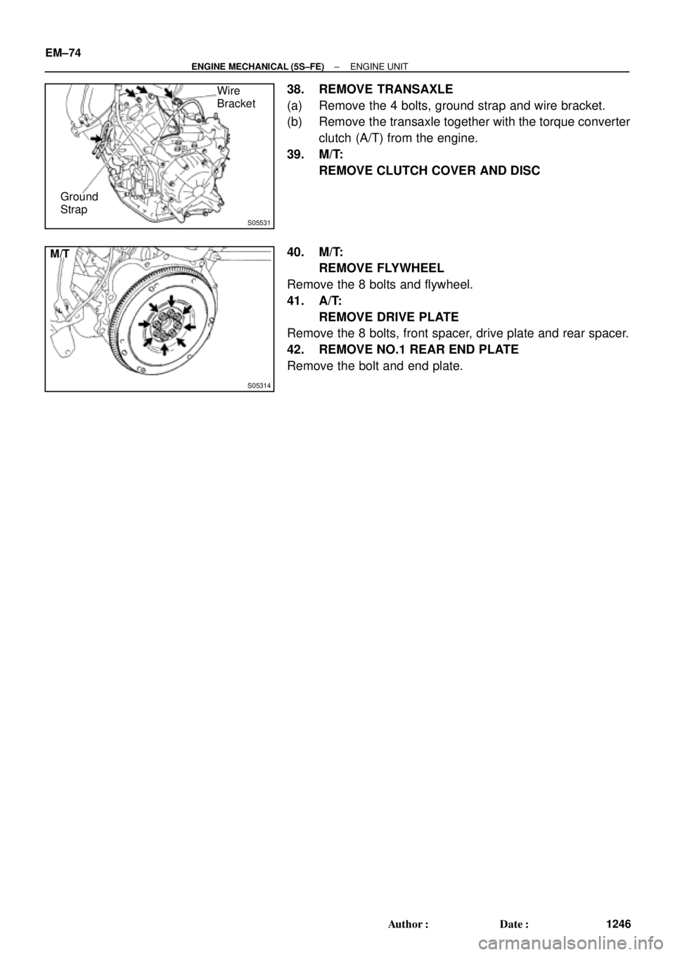
S05531
Wire
Bracket
Ground
Strap
S05314
M/T EM±74
± ENGINE MECHANICAL (5S±FE)ENGINE UNIT
1246 Author�: Date�:
38. REMOVE TRANSAXLE
(a) Remove the 4 bolts, ground strap and wire bracket.
(b) Remove the transaxle together with the torque converter
clutch (A/T) from the engine.
39. M/T:
REMOVE CLUTCH COVER AND DISC
40. M/T:
REMOVE FLYWHEEL
Remove the 8 bolts and flywheel.
41. A/T:
REMOVE DRIVE PLATE
Remove the 8 bolts, front spacer, drive plate and rear spacer.
42. REMOVE NO.1 REAR END PLATE
Remove the bolt and end plate.

47 (480, 35)
Clutch Coverx 6
Release Bearing and Hub
Release Fork5S±FE :
Release Fork
39 (400, 29)
5S±FE :
Clutch Disc
N´m (kgf´cm, ft´lbf) : Sp")

(TMC Made)
Exhaust Pipe Bracket
Oil Pan
Insulator
No.1 Exhaust
Manifold Stay
Back±Up Light Switch ConnectorNo.2 Rear End Plate Flywheel
LH Sti")