Page 1938 of 4770
VALVE BODY ASSEMBLY
1930 Author�: Date�:
(d) Coat the 2 new O±rings with ATF and install it to the shift
solenoid")
Q05402
Q05643
OR0038
D01023
A
C
CB
C
DD
D01058
AX±10
± AUTOMATIC TRANSAXLE (A541E)VALVE BODY ASSEMBLY
1930 Author�: Date�:
(d) Coat the 2 new O±rings with ATF and install it to the shift
solenoid valve SLN.
(e) Install the shift solenoid valve SLN.
(f) Install and torque the bolt.
Torque: 6.6 N´m (67 kgf´cm, 58 in.´lbf)
(g) Coat the 2 new O±rings with ATF and install it to the shift
solenoid valve No.1 and No.2.
(h) Install the No.1 and No.2 solenoids.
(i) Install and torque the 3 bolts.
Torque: 6.6 N´m (67 kgf´cm, 58 in.´lbf)
15. PLACE NEW 2ND BRAKE APPLY GASKET
16. INSTALL VALVE BODY TO TRANSAXLE CASE
(a) While holding the cam down with your hand, slip the cable
end into the slot.
(b) Lower the valve body into place.
NOTICE:
Be careful not to entangle the solenoid wire.
(c) Install and tighten the 9 bolts.
HINT:
Hand tighten the 9 bolts first, then torque with a torque wrench.
Bolt length:
Bolt A: 30 mm (1.181 in.)
Bolt B: 43 mm (1.693 in.)
Bolt C: 48 mm (1.890 in.)
Bolt D: 52 mm (2.047 in.)
Torque: 11 N´m (110 kgf´cm, 8 ft´lbf)
17. INSTALL B
3 APPLY PIPE
NOTICE:
Be careful not to bend or damage the pipe.
Page 1939 of 4770

BAmm (in.)
Q05728
Connector
± AUTOMATIC TRANSAXLE (A541E)VALVE BODY ASSEMBLY
AX±11
1931 Author�: Date�:
18. INSTALL CONNECTOR CLAMP AND PIPE RETAINER
(a) Ins")
D01059
A
B
D01021
B
B
A
Z19257
30
(1.18)
BAmm (in.)
Q05728
Connector
± AUTOMATIC TRANSAXLE (A541E)VALVE BODY ASSEMBLY
AX±11
1931 Author�: Date�:
18. INSTALL CONNECTOR CLAMP AND PIPE RETAINER
(a) Install the connector clamp and pipe retainer.
(b) Install and torque the 2 bolts.
Bolt length:
Bolt A: 48 mm (1.890 in.)
Bolt B: 39 mm (1.535 in.)
Torque: 11 N´m (110 kgf´cm, 8 ft´lbf)
19. INSTALL MANUAL VALVE BODY
(a) Align the manual valve with the pin on the manual shaft
lever.
(b) Lower the manual valve body into place.
(c) Hand tighten the 5 bolts first. Then, tighten them with a
torque wrench.
Bolt length:
Bolt A: 22 mm (0.866 in.)
Bolt B: 37 mm (1.457 in.)
Torque: 11 N´m (110 kgf´cm, 8 ft´lbf)
20. INSTALL DETENT SPRING AND OIL PIPE
(a) Place the detent springs on the manual valve body and
hand tighten the 2 bolts first. Then, tighten them with a
torque wrench.
Bolt length:
Bolt A: 14 mm (0.551 in.)
Bolt B: 37 mm (1.457 in.)
Torque: 11 N´m (110 kgf´cm, 8 ft´lbf)
(b) Check that the manual valve lever is touching the center
of the detent spring tip roller.
(c) Using a plastic hammer, install the pipe into the position.
NOTICE:
Be careful not to bend or damage the pipe.
(d) Install and torque the bolt.
Torque: 10 N´m (100 kgf´cm, 7 ft´lbf)
21. CONNECT SOLENOID CONNECTORS
22. INSTALL OIL PIPES
Using a plastic hammer, install the pipes into the positions.
NOTICE:
Be careful not to bend or damage the pipes.
Page 1940 of 4770
Z19256
BA
B A
AT3741
AT3785
AX±12
± AUTOMATIC TRANSAXLE (A541E)VALVE BODY ASSEMBLY
1932 Author�: Date�:
23. INSTALL OIL STRAINER AND APPLY PIPE BRACKET
(a) Install the oil strainer and apply pipe bracket.
(b) Install and torque the 6 bolts.
Bolt length:
Bolt A: 22 mm (0.866 in.)
Bolt B: 53 mm (2.087 in.)
Torque:
Bolt A: 10 N´m (100 kgf´cm, 7 ft´lbf)
Bolt B: 11 N´m (110 kgf´cm, 8 ft´lbf)
24. INSTALL MAGNETS IN PLACE
Install the 3 magnets in the indentations of the oil pan, as shown
in the illustration.
NOTICE:
Make sure that the magnet does not interfere with the oil
pipes.
25. INSTALL OIL PAN AND GASKET
(a) Install the oil pan and a new gasket.
(b) Install and torque the 17 new bolts.
Torque: 7.8 N´m (80 kgf´cm, 69 in.´lbf)
26. INSTALL AND TORQUE DRAIN PLUG
Torque: 49 N´m (500 kgf´cm, 36 ft´lbf)
27. FILL ATF AND CHECK FLUID LEVEL
(See page DI±438)
Page 2084 of 4770
 if it has been use")
BO0NG±01
BO0632
BO0633
15°
45° BO±124
± BODYSEAT BELT
2472 Author�: Date�:
INSPECTION
CAUTION:
Replace the seat belt assembly (outer belt, inner belt, bolts,
nuts or sill±bar) if it has been used in a severe impact. The
entire assembly should be replaced even if damage is not
obvious.
1. All Seat Belt:
RUNNING TEST (IN SAFE AREA)
(a) Fasten the front seat belts.
(b) Drive the car at 10 mph (16 km/h) and slam on the brakes.
Check that the belt locks and cannot be extended at this
time.
HINT:
Conduct this test in a safe area. If the belt does not lock, remove
the belt mechanism assembly and conduct the following static
check. Also, whenever installing a new belt assembly, verify the
proper operation before installation.
2. Driver 's Seat Belt (ELR):
STATIC TEST
(a) Make sure that the belt locks when pulled out quickly.
(b) Remove the locking retractor assembly.
(c) Tilt the retractor slowly.
(d) Make sure that the belt can be pulled out at a tilt of 15 de-
grees or less, and cannot be pulled out over 45 degrees
of tilt.
If a problem is found, replace the assembly.
3. Front RH Seat Belt and Rear Seat Belt (ALR/ELR):
STATIC TEST
(a) Make sure that the belt locks when pulled out quickly.
(b) Remove the locking retractor assembly.
(c) Pull out the whole belt and measure the length of the
whole belt.
Then retract the belt slightly and pull it out again
(d) Make sure that the belt cannot be extended further.
If a problem is found, replace the assembly.
Page 2085 of 4770
N10070
Full Belt Length Minus
200 mm (7.87 in.)
BO0633
15°
45°
± BODYSEAT BELT
BO±125
2473 Author�: Date�:
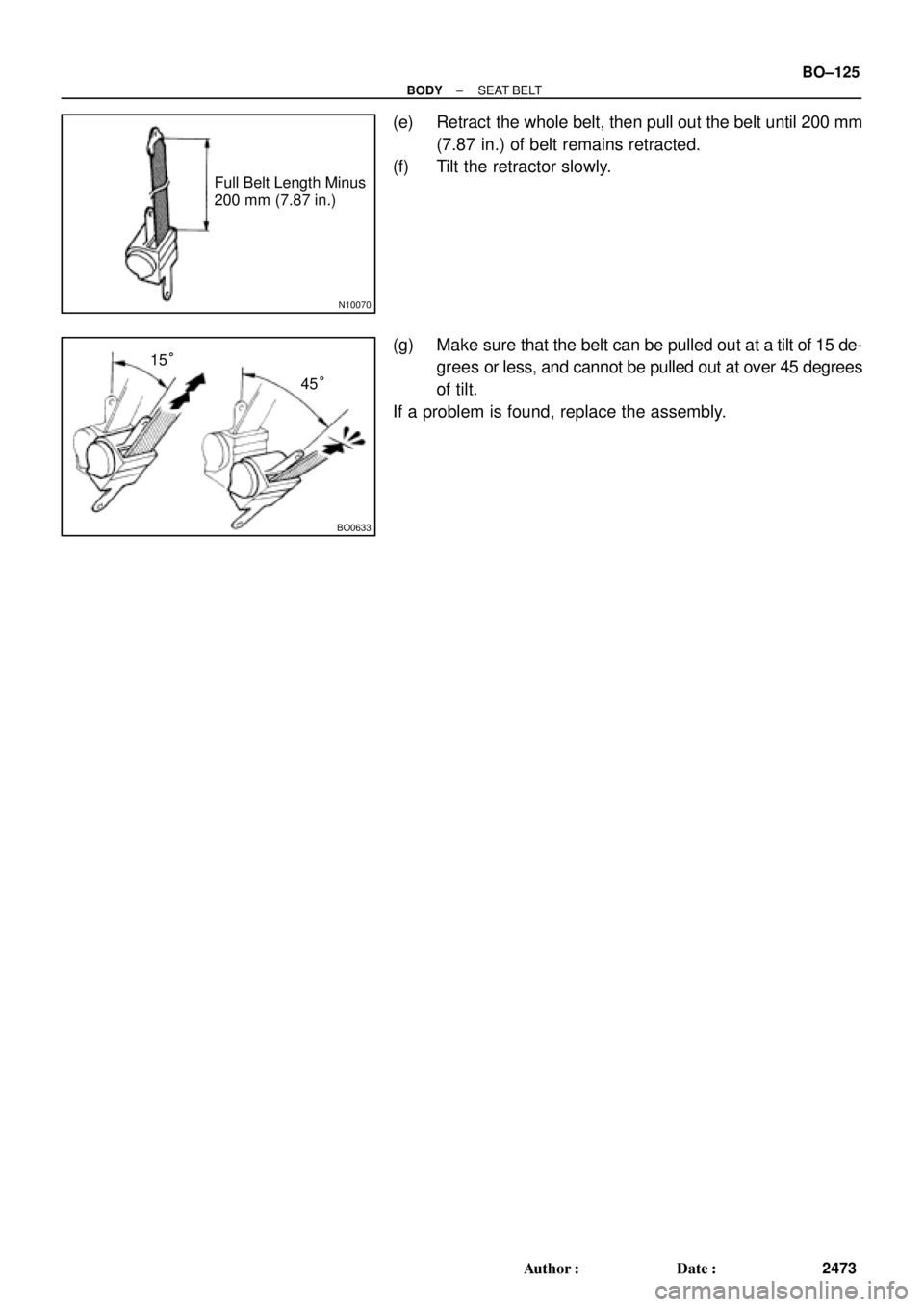
(e) Retract the whole belt, then pull out the belt until 200 mm
(7.87 in.) of belt remains retracted.
(f) Tilt the retractor slowly.
(g) Make sure that the belt can be pulled out at a tilt of 15 de-
grees or less, and cannot be pulled out at over 45 degrees
of tilt.
If a problem is found, replace the assembly.
Page 2238 of 4770
BR0AJ±02
BR±16
± BRAKEBRAKE MASTER CYLINDER
2039 Author�: Date�:
INSTALLATION
Installation is in the reverse order of removal (See page BR±11).
HINT:
�Before installation, adjust length of the brake booster push rod (See page BR±20).
�After installation, fill the brake reservoir with brake fluid, bleed the brake system and check for leaks
(See page BR±4).
�Check and adjust brake pedal (See page BR±5).
Page 2242 of 4770
 Install the booster and a new gasket.
(b) Install the clevis")
BR0AN±03
F03521
SST
Gasket
R11347
SST BR±20
± BRAKEBRAKE BOOSTER ASSEMBLY
2043 Author�: Date�:
INSTALLATION
1. INSTALL BRAKE BOOSTER
(a) Install the booster and a new gasket.
(b) Install the clevis to the operating rod.
(c) Install and torque the booster installation nuts.
Torque: 13 N´m (130 kgf´cm, 9 ft´lbf)
(d) Install the clevis, and torque the lock nut.
Torque: 25 N´m (260 kgf´cm, 19 ft´lbf)
(e) Install the clevis pin into the clevis and brake pedal, and
install the clip to the clevis pin.
(f) Install the pedal return spring.
2. ADJUST LENGTH OF BOOSTER PUSH ROD
(a) Install a new gasket on the master cylinder.
(b) Set the SST on the gasket, and lower the pin until its tip
slightly touches the piston.
SST 09737±00010
(c) Turn the SST upside down, and set it on the booster.
SST 09737±00010
(d) Measure the clearance between the booster push rod
and pin head (SST).
Clearance: 0 mm (0 in.)
(e) Adjust the booster push rod length until the push rod light-
ly touches the pin head.
3. INSTALL CHARCOAL CANISTER TO ORIGINAL POSI-
TION
4. INSTALL MASTER CYLINDER (See page BR±16)
5. INSTALL AIR CLEANER COVER WITH AIR CLEANER
HOSE
6. CONNECT VACUUM HOSE TO BRAKE BOOSTER
7. FILL BRAKE RESERVOIR WITH BRAKE FLUID AND
BLEED BRAKE SYSTEM (See page BR±4)
8. CHECK FOR FLUID LEAKAGE
9. CHECK AND ADJUST BRAKE PEDAL
(See page BR±5)
10. DO OPERATIONAL CHECK (See page BR±17)
Page 2257 of 4770
.
NOTICE:
Apply lithium soap base glyco")
BR0AZ±02
W01679
BR1553
F06423
± BRAKEREAR DRUM BRAKE
BR±35
2058 Author�: Date�:
INSTALLATION
Installation is in the reverse order of removal
(See page BR±32).
NOTICE:
Apply lithium soap base glycol grease and high tempera-
ture grease to the parts indicated by the arrows
(See page BR±31).
1. AFTER INSTALLATION, FILL BRAKE RESERVOIR
WITH BRAKE FLUID, BLEED BRAKE SYSTEM
(See page BR±4)
2. CHECK FOR LEAKS
3. CHECK OPERATION OF AUTOMATIC ADJUSTING
MECHANISM
(a) Move the parking brake lever of the rear shoe back and
forth. Check that the adjuster turns.
If the adjuster does not turn, check for incorrect installation of
the rear brake.
(b) Adjust the adjuster length as short as possible.
(c) Align the adjusting hole on the brake drum and the largest
hole on the axle carrier, install the brake drum.
(d) Pull the parking brake lever all the way up until a clicking
sound can no longer be heard.
4. CHECK CLEARANCE BETWEEN BRAKE SHOES AND
DRUM
(a) Remove the drum.
(b) Measure the brake drum inside diameter and diameter
between the brake shoes. Check that the difference be-
tween the diameters is the correct shoe clearance.
Shoe clearance: 0.6 mm (0.024 in.)
If incorrect, check the parking brake system.