Page 3438 of 4770
Z02852
45°
30°
1.0 ± 1.4 mm
Z02853
45° 75°
1.0 ± 1.4 mm
P03273
EM0988
Deviation
EM0801
EM±46
± ENGINE MECHANICAL (5S±FE)CYLINDER HEAD
1218 Author�: Date�:
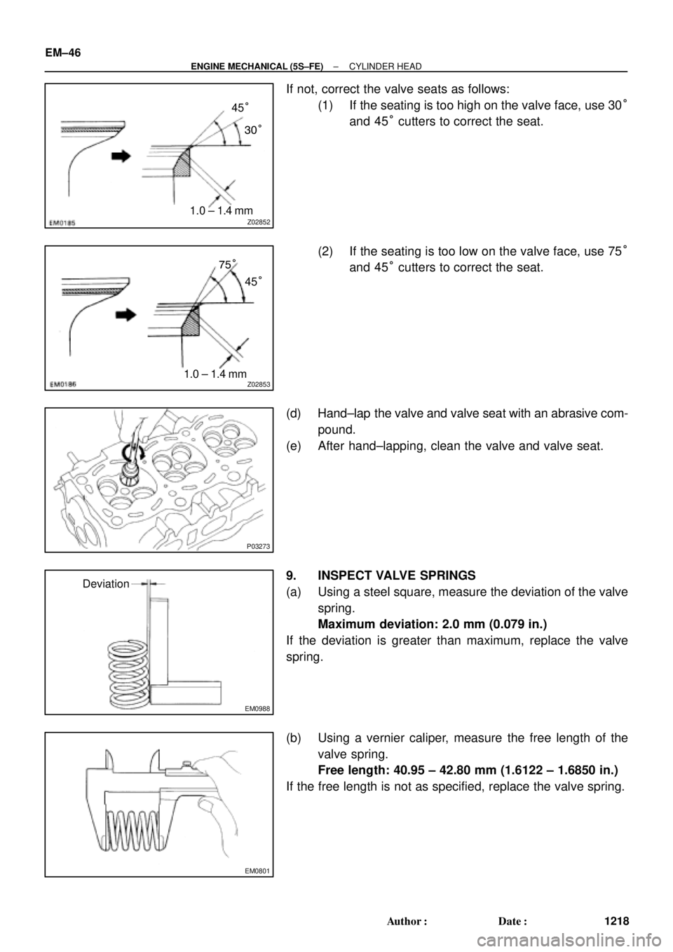
If not, correct the valve seats as follows:
(1) If the seating is too high on the valve face, use 30°
and 45° cutters to correct the seat.
(2) If the seating is too low on the valve face, use 75°
and 45° cutters to correct the seat.
(d) Hand±lap the valve and valve seat with an abrasive com-
pound.
(e) After hand±lapping, clean the valve and valve seat.
9. INSPECT VALVE SPRINGS
(a) Using a steel square, measure the deviation of the valve
spring.
Maximum deviation: 2.0 mm (0.079 in.)
If the deviation is greater than maximum, replace the valve
spring.
(b) Using a vernier caliper, measure the free length of the
valve spring.
Free length: 40.95 ± 42.80 mm (1.6122 ± 1.6850 in.)
If the free length is not as specified, replace the valve spring.
Page 3439 of 4770
CYLINDER HEAD
EM±47
1219 Author�: Date�:
(c) Using a spring tester, measure the tension of the valve
spring at the specif")
EM0281
EM1628
EM2011
EM2538
EM3322
Free Distance
± ENGINE MECHANICAL (5S±FE)CYLINDER HEAD
EM±47
1219 Author�: Date�:
(c) Using a spring tester, measure the tension of the valve
spring at the specified installed length.
Installed tension:
164 ± 189 N (16.7 ± 19.3 kgf, 36.8 ± 42.5 lbf)
at 34.7 mm (1.366 in.)
If the installed tension is not as specified, replace the valve
spring.
10. INSPECT CAMSHAFTS
(a) Inspect the circle runout.
(1) Place the camshaft on V±blocks.
(2) Using a dial indicator, measure the circle runout at
the center journal.
Maximum circle runout: 0.04 mm (0.0016 in.)
If the circle runout is greater than maximum, replace the cam-
shaft.
(b) Using a micrometer, measure the cam lobe height.
Standard cam lobe height:
Intake42.01 ± 42.11 mm (1.6539 ± 1.6579 in.)
Exhaust40.06 ± 40.16 mm (1.5772 ± 1.5811 in.)
Minimum cam lobe height:
Intake41.90 mm (1.6496 in.)
Exhaust39.95 mm (1.5728 in.)
If the cam lobe height is less than minimum, replace the cam-
shaft.
(c) Using a micrometer, measure the journal diameter.
Journal diameter:
26.959 ± 26.975 mm (1.0614 ± 1.0620 in.)
If the journal diameter is not as specified, check the oil clear-
ance.
(d) Using vernier calipers, measure the free distance be-
tween the gear spring ends.
Free distance: 22.5 ± 22.9 mm (0.886 ± 0.902 in.)
If the free distance is not as specified, replace the gear spring.
Page 3453 of 4770
(c)(d)
± ENGINE MECHANICAL (5S±FE)CYLINDER HEAD
EM±61
1233 Author�: Date�:
18. CONNECT FUEL INLET HOSE TO DELIVERY PIPE
(a) T")
S05982
SST
Fulcrum
Length
A07365
A07363
A07364
Clamp
Connector
A01564(b)(c)(d)
± ENGINE MECHANICAL (5S±FE)CYLINDER HEAD
EM±61
1233 Author�: Date�:
18. CONNECT FUEL INLET HOSE TO DELIVERY PIPE
(a) Temporarily connect the fuel inlet hose with 2 new gas-
kets and fuel pulsation damper.
(b) Using SST, tighten the fuel pulsation damper.
SST 09612±24014 (09617±24011)
Torque:
34 N´m (350 kgf´cm, 25 ft´lbf)
29 N´m (300 kgf´cm, 21 ft´lbf) for use with SST
HINT:
Use a torque wrench with a fulcrum length of 30 cm (1.181 in.).
19. INSTALL ENGINE WIRE
(a) Install the 2 engine wire clamps to the 2 brackets on the
front side of the intake manifold.
(b) Install the engine wire clamp to the bracket on the LH side
of the intake manifold.
20. INSTALL EGR VALVE AND VACUUM MODULATOR
(a) Install a new gasket, the EGR valve, EGR pipe and vacu-
um modulator assembly with the union nut, 2 nuts and
bolt.
Torque:
13.3 N´m (136 kgf´cm, 10 ft´lbf) for nut
61.2 N´m (624 kgf´cm, 45 ft´lbf) for union nut
(b) Install the hose clamp to the bracket on the intake man-
ifold.
(c) Install the VSV for the EGR with the bolt.
(d) Connect the VSV connector for the EGR.
21. INSTALL INTAKE MANIFOLD STAY
Install the intake manifold stay with the bolt and nut.
Torque: 39 N´m (398 kgf´cm, 29 ft´lbf)
22. INSTALL WATER OUTLET
(a) Install a new gasket and the water outlet with the 2 nuts.
Torque: 15 N´m (150 kgf´cm, 11 ft´lbf)
(b) Connect the radiator hose to the water outlet.
(c) Connect the water bypass pipe hose to the water outlet.
(d) Connect the heater water hose to the water outlet.
(e) Connect the ECT sensor connector.
(f) Connect the ECT sender gauge connector.
23. CONNECT OIL PRESSURE SWITCH CONNECTOR
24. CONNECT NOISE FILTER CONNECTOR
Page 3528 of 4770
TIMING BELT
1308 Author�: Date�:
(c) Using SST, install the pulley bolt.
SST 09249±63010, 09960±1")
P20069
Fulcrum
Length
SSTSST RH
P12762
SST LH
P18811
A05063
SST
EM±22
± ENGINE MECHANICAL (1MZ±FE)TIMING BELT
1308 Author�: Date�:
(c) Using SST, install the pulley bolt.
SST 09249±63010, 09960±10010 (09962±01000,
09963±01000)
Torque: 88 N´m (900 kgf´cm, 65 ft´lbf)
HINT:
Use a torque wrench with a fulcrum length of 340 mm (13.39
in.).
5. INSTALL LH CAMSHAFT TIMING PULLEY
(a) Face the flange side of the timing pulley inward.
(b) Align the knock pin on the camshaft with the knock pin
groove of the timing pulley, and slide on the timing pulley.
(c) Using SST, install the pulley bolt.
SST 09960±10010 (09962±01000, 09963±01000)
Torque: 125 N´m (1,300 kgf´cm, 94 ft´lbf)
6. SET NO.1 CYLINDER TO TDC/COMPRESSION
(a) Crankshaft Timing Pulley Position:
Temporarily install the crankshaft pulley bolt to the crank-
shaft.
(b) Crankshaft Timing Pulley Position:
Turn the crankshaft, and align the timing marks of the
crankshaft timing pulley and oil pump body.
(c) Camshaft Timing Pulley Positions:
Using SST, turn the camshaft pulley, align the timing
marks of the timing pulley and No.3 timing belt cover.
SST 09960±10010 (09962±01000, 09963±01000)
Page 3530 of 4770

P18815
EM±24
± ENGINE MECHANICAL (1MZ±FE)TIMING BELT
1310 Author�: Date�:
10. CHECK VALVE TIMING
(a) Slowly turn the crankshaft 2 revolutions, and")
P18808
A05052
P12983
Length = 1,410 mm (55.51 in.)
P18815
EM±24
± ENGINE MECHANICAL (1MZ±FE)TIMING BELT
1310 Author�: Date�:
10. CHECK VALVE TIMING
(a) Slowly turn the crankshaft 2 revolutions, and align the tim-
ing marks of the crankshaft timing pulley and oil pump
body.
NOTICE:
Always turn the crankshaft clockwise.
(b) Check that the timing marks of the RH and LH timing pul-
leys with the timing marks of the No.3 timing belt cover as
shown in the illustration.
If the marks do not align, remove the timing belt and reinstall it.
(c) Remove the crankshaft pulley bolt.
11. INSTALL RH ENGINE MOUNTING BRACKET
Torque: 28 N´m (290 kgf´cm, 21 ft´lbf)
12. INSTALL NO.2 TIMING BELT COVER
(a) Check that the timing belt cover gasket has no cracks or
peeling, etc.
If the gasket has cracks or peeling, etc., replace it using these
steps:
�Using a screwdriver and gasket scraper, remove all
the old gasket material.
�Thoroughly clean all components to remove all the
loose material.
�Remove the backing paper from a new gasket and
install the gasket evenly to the part of the timing belt
cover shaded black in the illustration.
�After installing the gasket, press down on it so that
the adhesive firmly sticks to the timing belt cover.
(b) Install the timing belt cover with the 5 bolts.
Torque: 8.5 N´m (85 kgf´cm, 74 in.´lbf)
(c) Install the engine wire protector clamps to the No.3 timing
belt cover.
13. INSTALL TIMING BELT GUIDE
Install the timing belt guide, facing the cup side outward.
Page 3531 of 4770

Join
Line
Join
Line
Length = 460 mm
(18.11 in.)
A04693
SST
P18816
± ENGINE MECHANICAL (1MZ±FE)TIMING BELT
EM±25
1311 Author�: Date�:
14. INSTALL NO.1 TIMING BELT C")
P12982
Length = 240 mm (9.45 in.)
Join
Line
Join
Line
Length = 460 mm
(18.11 in.)
A04693
SST
P18816
± ENGINE MECHANICAL (1MZ±FE)TIMING BELT
EM±25
1311 Author�: Date�:
14. INSTALL NO.1 TIMING BELT COVER
(a) Check that the timing belt cover gaskets have cracks or
peeling, etc.
If the gasket has cracks or peeling, etc., replace it using these
steps:
�Using a screwdriver and gasket scraper, remove all
the old gasket material.
�Thoroughly clean all components to remove all the
loose material.
�Remove the backing paper from a new gasket and
install the gasket evenly to the part of the timing belt
cover shaded black in the illustration.
NOTICE:
When joining 2 gaskets, do not leave a gap between them.
Cut off any excess gasket.
�After installing the gasket, press down on it so that
the adhesive firmly sticks to the timing belt cover.
(b) Install the timing belt cover with the 4 bolts.
Torque: 8.5 N´m (85 kgf´cm, 74 in.´lbf)
15. INSTALL CRANKSHAFT PULLEY
(a) Align the pulley set key with the key groove of the pulley,
and slide on the pulley.
(b) Using SST, install the pulley bolt.
SST 09213±54015 (91651±60855), 09330±00021
Torque: 215 N´m (2,200 kgf´cm, 159 ft´lbf)
16. INSTALL NO.2 GENERATOR BRACKET
Install the generator bracket with the pivot bolt and nut. Do not
tighten the bolt yet.
Torque: (Nut): 28 N´m (290 kgf´cm, 21 ft´lbf)
17. INSTALL NO.2 RH ENGINE MOUNTING BRACKET,
ENGINE MOVING CONTROL ROD, NO.2 RH ENGINE
MOUNTING STAY (M/T) AND RH ENGINE MOUNTING
STAY (See page EM±76)
18. CONNECT GROUND STRAP CONNECTORS
19. CONNECT ENGINE COOLANT RESERVOIR HOSE TO
WATER OUTLET
20. INSTALL PS PUMP DRIVE BELT
21. INSTALL GENERATOR DRIVE BELT
(See page CH±16)
Page 3543 of 4770
CYLINDER HEAD
EM±37
1323 Author�: Date�:
29. REMOVE OIL DIPSTICK AND GUIDE
(a) Re")
P12710
O±Ring
A01816
P12811Align Intake
P12871
Main Gear
Sub±Gear
Service Bolt Intake
± ENGINE MECHANICAL (1MZ±FE)CYLINDER HEAD
EM±37
1323 Author�: Date�:
29. REMOVE OIL DIPSTICK AND GUIDE
(a) Remove the bolt holding the dipstick guide to the LH cylin-
der head.
(b) Pull out the dipstick guide together with the dipstick from
the No.1 oil pan.
(c) Remove the O±ring from the dipstick guide.
30. REMOVE CYLINDER HEAD COVERS
Remove the 8 bolts, cylinder head cover and gasket. Remove
the 2 cylinder head covers.
31. REMOVE CAMSHAFTS OF RH CYLINDER HEAD
NOTICE:
Since the thrust clearance of the camshaft is small, the
camshaft must be held level while it is being removed. If the
camshaft is not kept level, the portion of the cylinder head
receiving the shaft thrust may crack or be damaged, caus-
ing the camshaft to seize or break. To avoid this, the follow-
ing steps should be carried out.
(a) Remove the intake camshaft.
(1) Align the timing marks (2 dot marks) of the camshaft
drive and driven gears by turning the camshaft with
a wrench.
(2) Secure the exhaust camshaft sub±gear to the main
gear with a service bolt.
Recommended service bolt:
Thread diameter6 mm
Thread pitch1.0 mm
Bolt length16 ± 20 mm (0.63 ± 0.79 in.)
Page 3545 of 4770
CYLINDER HEAD
EM±39
1325 Author�: Date�:
(2) Secur")
P12873Main Gear
Sub±GearService Bolt Intake
P12958
Intake
7
85
6
3
41
2
9
10
P12886
7
85 6
3 41 2
9 10 Exhaust
P12596
± ENGINE MECHANICAL (1MZ±FE)CYLINDER HEAD
EM±39
1325 Author�: Date�:
(2) Secure the exhaust camshaft sub±gear to the main
gear with a service bolt.
Recommended service bolt:
Thread diameter6 mm
Thread pitch1.0 mm
Bolt length16 ± 20 mm (0.63 ± 0.79 in.)
HINT:
When removing the camshaft, make sure that the torsional
spring force of the sub±gear has been eliminated by the above
operation.
(b) Uniformly loosen and remove the 10 bearing cap bolts, in
several passes, in the sequence shown.
(c) Remove the 5 bearing caps and intake camshaft.
(d) Remove the exhaust camshaft.
(1) Uniformly loosen and remove the 10 bearing cap
bolts, in several passes, in the sequence shown.
(2) Remove the 5 bearing caps, oil seal and exhaust
camshaft.
HINT:
�Arrange the camshafts in the correct order.
�Arrange the bearing caps in the correct order.
33. DISASSEMBLE EXHAUST CAMSHAFTS
(a) Mount the hexagonal wrench head portion of the cam-
shaft in a vise.
NOTICE:
Be careful not to damage the camshaft.