Page 401 of 4770
CIRCUIT DESCRIPTION
The signal from the A/T CPU retards the ignition timing of the engine during A/T shifting, thus
momentarily reducing torque output of the engine for smooth clutch operation inside the transmis-
sion and reduced shift shock.
If the ECM detects the diagnostic trouble code ª16º in memory, it prohibits the torque control of the
A/T which performs smooth gear shifting.
Are there any other codes (besides Code 16)
being output?Fault in communications between the engine
CPU and A/T CPU in the ECM
Go to relevant diagnostic trouble code
chart. Diagnostic Trouble Code Detecting Condition
DIAGNOSTIC CHART
Replace ECM.Trouble Area
DTC 16 A±T Control Signal Malfunction
DTC No.
wECM
YES
± 5S±FE ENGINECIRCUIT INSPECTIONEG1±351
Page 489 of 4770
u
Type5S±FE: In±Line 4, 2.2±Literu
D")
8
MAJOR COMPONENTS
The basic components of the new and previous Camry are as follows:
Model
NEWPREVIOUSItemNEWPREVIOUS
Drive SystemFF (Front Engine Wheel Drive)u
Type5S±FE: In±Line 4, 2.2±Literu
Displacement cm3 (cu. in.)2164 (132.0)u
Valve Mechanism16 Valves, DOHCu
eFuel SystemSFIu
n±Line
Engine
Max. Output [SAE±NET]
kW @ rpm (HP @ rpm)99 @ 5200 (133 @ 5200)
97 @ 5200 (130 @ 5200)*93 @ 5400 (125 @ 5400)
In± 4
E
Max. Torque [SAE±NET]
N
.m @ rpm (ft.lbf @ rpm)
199 @ 4400 (147 @ 4400)
197 @ 4400 (145 @ 4400)*197 @ 4400 (145 @ 4400)
Type1MZ±FE: V6, 3.0±Literu
Displacement cm3 (cu. in.)2995 (182.7)u
Valve Mechanism24 Valves, DOHCu
Fuel SystemSFIu
Engine
Max. Output [SAE±NET]
kW @ rpm (HP @ rpm)145 @ 5200 (194 @ 5200)140 @ 5200 (188 @ 5200)
V6
E
Max. Torque [SAE±NET]
N
.m @ rpm (ft.lbf @ rpm)283 @ 4400 (209 @ 4400)275 @ 4400 (203 @ 4400)
ClutchDry Type Single Plateu
Transaxle
Manual S51: 5±Speed (For 5S±FE)
E153: 5±Speed (For 1MZ±FE) S51: 5±Speed (For 5S±FE)
AutomaticA140E: 4±Speed (For 5S±FE)
A541E: 4±Speed (For 1MZ±FE)u
FrontVentilated Discu
BrakesRearSXV20 Series : Leading Trailing Drum
MCV20 Series : Solid Disc
SXV10 Series without ABS:
Leading Trailing Drum
SXV10 Series with ABS
and MCV10 Series: Solid Disc
Suspension4±Wheel MacPherson Strutu
SteeringGear TypeRack and PinionuSteeringPower SteeringEngine Revolution Sensing Typeu
*: California Specification Model
Page 490 of 4770
![TOYOTA CAMRY 2000 Service Repair Manual 9
ENGINE
ENGINE LINE±UP
2 types of engine are available in the Camry, the 2.2±liter 5S±FE and the 3.0±liter 1MZ±FE engines.
Displace±
ment
Engine
TypeMax. Output
[SAE±NET]Max. Torque
[SAE±NET]](/manual-img/14/57447/w960_57447-489.png "TOYOTA CAMRY 2000 Service Repair Manual 9
ENGINE
ENGINE LINE±UP
2 types of engine are available in the Camry, the 2.2±liter 5S±FE and the 3.0±liter 1MZ±FE engines.
Displace±
ment
Engine
TypeMax. Output
[SAE±NET]Max. Torque
[SAE±NET]")
9
ENGINE
ENGINE LINE±UP
2 types of engine are available in the Camry, the 2.2±liter 5S±FE and the 3.0±liter 1MZ±FE engines.
Displace±
ment
Engine
TypeMax. Output
[SAE±NET]Max. Torque
[SAE±NET]Features
2.2 liters5S±FE
99 kW @ 5200 rpm
(133 HP @ 5200 rpm)
97 kW @ 5200 rpm*
(130 HP @ 5200 rpm)*199 N.m @ 4400 rpm
(147 ft
.lbf @ 4400 rpm)
197 N
.m @ 4400 rpm*
(145 ft
.lbf @ 4400 rpm)*
The 5S±FE engine offers increased
torque in the low± to mid±speed
range and reduced exhaust
emissions.
3.0 liters1MZ±FE145 kW @ 5200 rpm
(194 HP @ 5200 rpm)283 N.m @ 4400 rpm
(209 ft
.lbf @ 4400 rpm)
The 1MZ±FE engine achieves
reduced exhaust emissions.
*: California Specification Models
� 5S±FE Engine
The 5S±FE engine is a 2.2±liter, 16±valve DOHC engine. Through the use of optimized intake and exhaust systems
and combustion chamber, this engine has improved its torque in the low± to mid±speed range. In addition, its
exhausts emissions have been reduced through the improvement of the engine control system.
� 1MZ±FE ENGINE
The 1MZ±FE engine is a V6, 3.0±liter, 24±valve DOHC engine. Through the adoption of the fuel returnless system
and the changes made to the EGR control system, the 1MZ±FE engine achieves a reduction of exhaust emissions.
Page 509 of 4770

30
ENGINE
5S±FE ENGINE
� DESCRIPTION
The 5S±FE engine has improved the torque in the low±to±mid±speed range through improvements made for the intake
and exhaust systems and the combustion chamber. In addition, its exhaust emissions have been reduced through the
improvements made for the exhaust system and the engine control system.
� ENGINE SPECIFICATIONS AND PERFORMANCE CURVE
5S±FE EngineNewPreviousItemNewPrevious
No. of Cyls. & Arrangement6±Cylinder, In±Lineu
Valve Mechanisms16±Valve DOHC,
Belt & Gear Driveu
Combustion ChamberPentroof Typeu
ManifoldsCross±Flowu
Fuel SystemSFIu
Displacement cm3(cu. in.)2164 (132.0)u
Bore x Stroke mm (in.)87.0 x 91.0 (3.43 x 3.58)u
Compression Ratio9.5 : 1u
Max. Output [SAE±NET]
99 kW @ 5200 rpm
(133 HP @ 5200 rpm)
97 kW @ 5200 rpm*
(130 HP @ 5200 rpm)*
93 kW @ 5400 rpm
(125 HP @ 5400 rpm)
Max. Output [SAE±NET]
199 N.m @ 4400 rpm
(147 ft
.lbf @ 4400 rpm)
197 N
.m @ 4400 rpm*
(145 HP @ 4400 rpm)*
197 N.m @ 4400 rpm
(145 ft
.lbf @ 4400 rpm)
IntakeOpen3o BTDCu
Valve Timing
IntakeClose43o ABDCuValve Timing
ExhaustOpen45o
BBDCuExhaustClose3o
ATDCu
Fuel Octane Number RON91u
Oil GradeAPI SH EC±II, ILDAC or Betteru
*: California Specification Model
Page 511 of 4770

32ENGINEÐ5S±FE ENGINE
� MAJOR DIFFERENCES
Major differences between the new 5S±FE engine and previous engine are listed below.
Item
Features
Engine ProperThe squish area of the combustion chamber in the cylinder head has been
optimised to improve torque in the low±to mid±speed range.
Cooling SystemAn aluminum radiator core is used for weight reduction.
Intake and Exhaust System
�The ports of the manifold have been extended to improve torque in the low±
to mid±speed range.
�The exhaust manifold is made of stainless steel plates for improve engine per-
formance and weight reduction.
�Through the optimized allocation of the exhaust pipe supports, the number of
supports has been reduced from 5 to 4, thus reducing the noise and vibration
which are transmitted to the vehicle body.
Fuel SystemA fuel returnless system has been adopted to prevent the internal temperature
of the fuel tank from rising and to reduce evaporative emissions.
Ignition SystemThe DIS (Direct Ignition System) contributes to the powerful high output by
providing a powerful spark to the engine.
Engine MountingTo reduce noise and vibration and to improve drivability, the allocation of the
engine mounts*1 and their characteristics have been revised.
Engine Control System
�The injection pattern for engine starting have changed form the 2 group
injection type to sequential multiport injection type.
�In place of the oxygen sensor (bank 1, sensor 1), a new air fuel ratio sensor has
been adopted. *
2
�The power steering idle±up control has been changed from the system using
an air control valve to the one using a pressure switch and an IAC valve.
Emission Control System
�The EGR valve body has been changed from cast iron to aluminum alloy for
weight reduction.
�A TWC (Three±Way Catalytic Converter) that is integrated with a stainless
steel exhaust manifold has been adopted.*
2
�The TWC, which was previously installed below the exhaust manifold has
been discontinued.*3
*1: Only for Automatic Transaxle Models.
*
2: Only for California Specification Models.
*
3: Except for California Specification Models.
Page 512 of 4770
33 ENGINEÐ5S±FE ENGINE
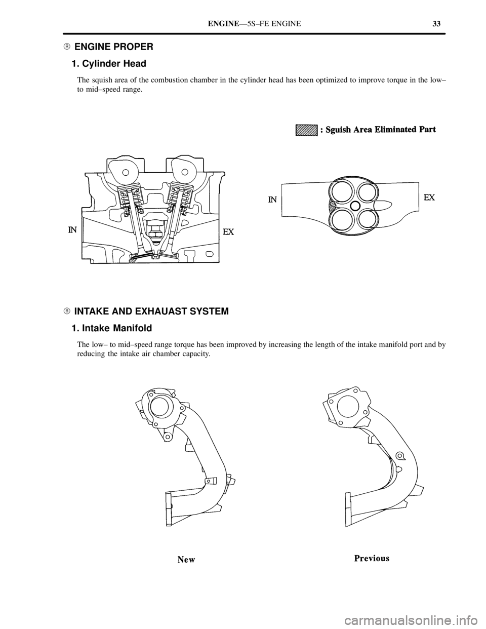
� ENGINE PROPER
1. Cylinder Head
The squish area of the combustion chamber in the cylinder head has been optimized to improve torque in the low±
to mid±speed range.
� INTAKE AND EXHAUAST SYSTEM
1. Intake Manifold
The low± to mid±speed range torque has been improved by increasing the length of the intake manifold port and by
reducing the intake air chamber capacity.
Page 516 of 4770

37 ENGINEÐ5S±FE ENGINE
� ENGINE CONTROL SYSTEM
1. General
The engine control system of the new 5S±FE engine is basically the same in construction and operation as that of the
previous 5S±FE engine, except fo rthe changed listed bleow.
�The exhaust emissions has been reduced through the adoption of the sequential multiport fuel injection system for
engine starting and the air±fuel ratio sensor*
2
�The function of an air conditioning amplifier has been internally added to the ECM.
The engine control system of the new 5S±FE engine and previous 5S±FE engine and previous 5S±FE engine are
compared below.
System
OutlineNewPrevious
SFI
(SequentialA D±type SFI system is used, which indirectly detects
intake air volume by manifold absolute pressure.��(q
Multiport Fuel
Injection)The fuel injection system is a sequential multiport fuel
injection system.��
ESA
(Electronic SparkIgnition Timing is determined by the ECM based on
signals from various sensors. The ECM corrects ignition
timing in response to engine knocking.
��
(Electronic Spark
Advance)Torque control correction during gear shifting has been
used to minimize the shift shock.��*1��*1
IACA rotary solenoid type IAC valve controls the fast idle��(Idle Air Control)
A rotary solenoid type IAC valve controls the fast idle
and idle speeds.��
Fuel Pump
ControlFuel pump operation is controlled by signal from the
ECM.��
Oxygen Sensor
(Air Fuel Ratio
Sensor*
2)
Heater Control
Maintains the temperature of the oxygen sensor (or air
fuel ratio sensor*2) at an approppiate level to increase
accuracy of detection of the oxygen concentration in the
exhaust gas.�Ð
EGR Cut±Off
ControlCuts off EGR according to the engine condition to
maintain drivability of the vehicle and durability of
EGR components.
��
Evaporative
Emission ControlThe ECM controls the purge flow of evaporative emis-
sions (HC) in the charcoal canister in accordance with
engine conditions.
��*1��*1
Air Conditioning
Cut±Off ControlBy turning the air conditioning compressor ON or
OFF in accordance with the engine condition,
drivability is maintained
��*3�
Diagnosis
When the ECM detects a malfunction, the ECM diagnoses
and memorized the failed section.��
DiagnosisThe diagnosis system includes a function that detects a
malfunction in the evaporative control system.��*1��*1
Fail SafeWhen the ECM detects a malfunction, the ECM stops
or controls the engine according to the data already stored
in memory
��
*1: Only for Automatic Transaxle Models., *2: Only for California Specification Models,
*
3: The air conditioning magnet scutch controled by the ECM.
Page 525 of 4770

46ENGINEÐ1MZ±FE ENGINE
� MAJOR DIFFERNCES
Major differences between the new 1MZ±FE engne and previous engine are listed below.
Item
Outline
Cooling SystemAn aluminum radiator core is used for weight reduction.
Intake and Exhaust System
Through the optimized allocation of the exhaust pipe supports, the number
number of supports has been reduced from 5 to 4, thus reducing the noise
and vibration which are transmitted to the vehicle body.
Fuel SystemA fuel returnless system has been adopted to prevent the internal temperature
of the fuel tank from rising, and to reduce evaporative emissions.
Engine MountingThe characteristics of the engine mounts, torque rod, and absorber have been
optimized to reduce noise and vibration.
Engine Control System
�A communication circuit has been provided between the ECM and the
ABS & TRAC ECU in conjunction with the adoption of the TRAC
(Traction Control) system.*
�The fuel pressure control has been discontinued in conjunction with the
adoption of the fuel returnless system.
�Instead of using the IDL signal input from the throttle position sensor,
the ECM now uses the VTA signal to detect the completely closed state of
the throttle valve.
�A new EGR system which uses a EGR valve position sensor is used.
�A communication method of the ECM and the hand±held tester has been
changed from the SAEJ1962 to the ISO 9141±2.
*: Applicable only to Vehicle Equipped with the TRAC System.