Page 969 of 1033

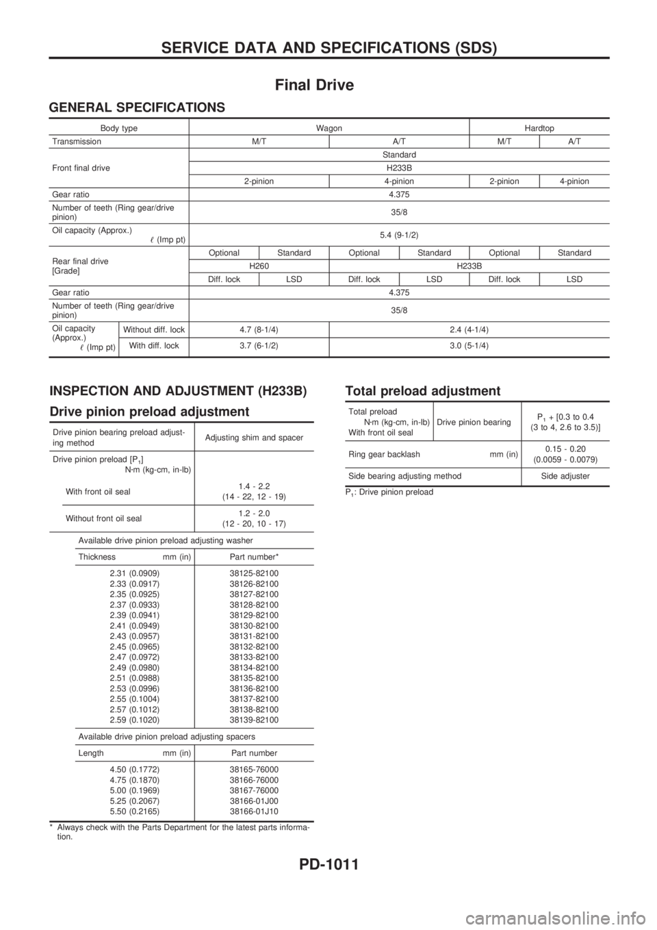
Final Drive
GENERAL SPECIFICATIONS
Body type Wagon Hardtop
Transmission M/T A/T M/T A/T
Front final drive Standard
H233B
2-pinion 4-pinion 2-pinion 4-pinion
Gear ratio 4.375
Number of teeth (Ring gear/drive
pinion) 35/8
Oil capacity (Approx.) !(Imp pt) 5.4 (9-1/2)
Rear final drive
[Grade] Optional Standard Optional Standard Optional Standard
H260 H233B
Diff. lock LSD Diff. lock LSD Diff. lock LSD
Gear ratio 4.375
Number of teeth (Ring gear/drive
pinion) 35/8
Oil capacity
(Approx.) !(Imp pt) Without diff. lock 4.7 (8-1/4) 2.4 (4-1/4)
With diff. lock 3.7 (6-1/2) 3.0 (5-1/4)
INSPECTION AND ADJUSTMENT (H233B)
Drive pinion preload adjustment
Drive pinion bearing preload adjust-
ing method Adjusting shim and spacer
Drive pinion preload [P
1]
N zm (kg-cm, in-lb)
With front oil seal 1.4 - 2.2
(14 - 22, 12 - 19)
Without front oil seal 1.2 - 2.0
(12 - 20, 10 - 17)
Available drive pinion preload adjusting washer
Thickness mm (in) Part number* 2.31 (0.0909)
2.33 (0.0917)
2.35 (0.0925)
2.37 (0.0933)
2.39 (0.0941)
2.41 (0.0949)
2.43 (0.0957)
2.45 (0.0965)
2.47 (0.0972)
2.49 (0.0980)
2.51 (0.0988)
2.53 (0.0996)
2.55 (0.1004)
2.57 (0.1012)
2.59 (0.1020) 38125-82100
38126-82100
38127-82100
38128-82100
38129-82100
38130-82100
38131-82100
38132-82100
38133-82100
38134-82100
38135-82100
38136-82100
38137-82100
38138-82100
38139-82100
Available drive pinion preload adjusting spacers
Length mm (in) Part number 4.50 (0.1772)
4.75 (0.1870)
5.00 (0.1969)
5.25 (0.2067)
5.50 (0.2165) 38165-76000
38166-76000
38167-76000
38166-01J00
38166-01J10
* Always check with the Parts Department for the latest parts informa- tion.
Total preload adjustment
Total preload
Nzm (kg-cm, in-lb)
With front oil seal Drive pinion bearing
P1+ [0.3 to 0.4
(3 to 4, 2.6 to 3.5)]
Ring gear backlash mm (in) 0.15 - 0.20
(0.0059 - 0.0079)
Side bearing adjusting method Side adjuster
P1: Drive pinion preload
SERVICE DATA AND SPECIFICATIONS (SDS)
PD-1011
Page 976 of 1033
Description
The air bag deploys if the diagnosis sensor unit activates while the ignition switch is in the ªONº or ªSTARTº
position.
The collision modes for which supplemental restraint systems are activated are different among the SRS
systems. For example, the driver air bag module and passenger air bag module are activated in a frontal
collision but not in a side collision.
SRS configurations which are activated for some collision modes are as follows;
SRS configuration Frontal collision Left side collision Right side collision
Driver air bag modulejÐÐ
Passenger air bag modulejÐÐ
Seat belt pre-tensioner (Driver side)jÐÐ
Seat belt pre-tensioner (Passenger side)jÐÐ
Side air bag module (LH) ÐjÐ
Side air bag module (RH) Ð Ðj
Built-in Type Side Air Bag
Front side air bag is built-in type.
The front seat backs with built-in type side air bag have the labels
shown in figures at left.
SRS585-A
SRS755
SUPPLEMENTAL RESTRAINT SYSTEM (SRS)
RS-1004
Page 993 of 1033
![NISSAN PATROL 2000 Electronic Repair Manual HOW TO ERASE SELF-DIAGNOSIS RESULTS
With CONSULT-II
+ªSELF-DIAG [CURRENT]º
A current Self-diagnosis result is displayed on the CONSULT-II screen in real time. After the malfunc-
tion is repaired com NISSAN PATROL 2000 Electronic Repair Manual HOW TO ERASE SELF-DIAGNOSIS RESULTS
With CONSULT-II
+ªSELF-DIAG [CURRENT]º
A current Self-diagnosis result is displayed on the CONSULT-II screen in real time. After the malfunc-
tion is repaired com](/manual-img/5/57367/w960_57367-992.png)
HOW TO ERASE SELF-DIAGNOSIS RESULTS
With CONSULT-II
+ªSELF-DIAG [CURRENT]º
A current Self-diagnosis result is displayed on the CONSULT-II screen in real time. After the malfunc-
tion is repaired completely, no malfunction is detected on ªSELF-DIAG [CURRENT]º.
+ªSELF-DIAG [PAST]º
Return to the ªSELF-DIAG [CURRENT]º CONSULT-II screen
by pushing ªBACKº key of CONSULT-II and select ªSELF-
DIAG [CURRENT]º in ªSELECT DIAG MODEº. Touch
ªERASEº in ªSELF-DIAG [CURRENT]º mode.
NOTE:
If the memory of the malfunction in ªSELF-DIAG [PAST]º is
not erased, the User mode shows the system malfunction by
the operation of the warning lamp even if the malfunction is
repaired completely.
+ªTROUBLE DIAG RECORDº
The memory of ªTROUBLE DIAG RECORDº cannot be erased.
Without CONSULT-II
After a malfunction is repaired, return Diagnosis mode to User mode by switching the ignition ªOFFº for at
least 1 second, then back ªONº. At that time, the self-diagnostic result is cleared.
How to Perform Trouble Diagnoses for Quick
and Accurate Repair
A good understanding of the malfunction conditions can make troubleshooting faster and more accurate.
In general, each customer feels differently about a malfunction. It is important to fully understand the symp-
toms or conditions for a customer complaint.
INFORMATION FROM CUSTOMER
WHAT ........ Vehicle model
WHEN ....... Date, Frequencies
WHERE ..... Road conditions
HOW .......... Operating conditions, Symptoms
PRELIMINARY CHECK
Check that the following parts are in good order.
+Battery [Refer to EL section (ªBATTERYº) of Service Manual.]
+Fuse [Refer to EL section (ªFuseº, ªPOWER SUPPLY ROUTINGº) of Service Manual.]
+System component-to-harness connections
SRS701
TROUBLE DIAGNOSES Ð Supplemental Restraint System (SRS)
Trouble Diagnoses Introduction (Cont'd)
RS-1021
Page 1004 of 1033

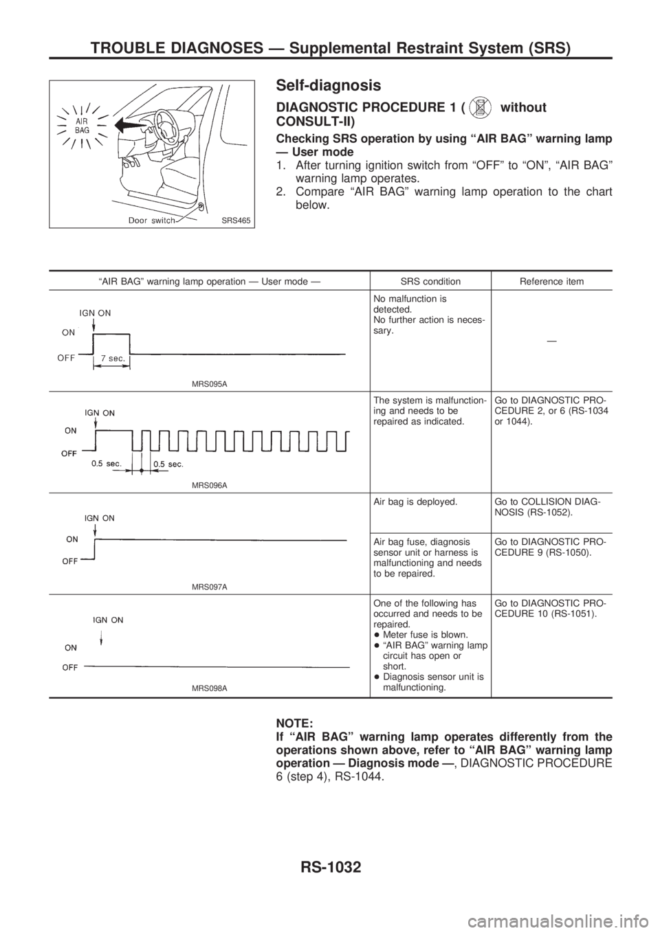
Self-diagnosis
DIAGNOSTIC PROCEDURE 1 (without
CONSULT-II)
Checking SRS operation by using ªAIR BAGº warning lamp
Ð User mode
1. After turning ignition switch from ªOFFº to ªONº, ªAIR BAGº
warning lamp operates.
2. Compare ªAIR BAGº warning lamp operation to the chart
below.
ªAIR BAGº warning lamp operation Ð User mode Ð SRS condition Reference item
MRS095A
No malfunction is
detected.
No further action is neces-
sary.
Ð
MRS096A
The system is malfunction-
ing and needs to be
repaired as indicated.Go to DIAGNOSTIC PRO-
CEDURE 2, or 6 (RS-1034
or 1044).
MRS097A
Air bag is deployed. Go to COLLISION DIAG-
NOSIS (RS-1052).
Air bag fuse, diagnosis
sensor unit or harness is
malfunctioning and needs
to be repaired.Go to DIAGNOSTIC PRO-
CEDURE 9 (RS-1050).
MRS098A
One of the following has
occurred and needs to be
repaired.
+Meter fuse is blown.
+ªAIR BAGº warning lamp
circuit has open or
short.
+Diagnosis sensor unit is
malfunctioning.Go to DIAGNOSTIC PRO-
CEDURE 10 (RS-1051).
NOTE:
If ªAIR BAGº warning lamp operates differently from the
operations shown above, refer to ªAIR BAGº warning lamp
operation Ð Diagnosis mode Ð, DIAGNOSTIC PROCEDURE
6 (step 4), RS-1044.
SRS465
TROUBLE DIAGNOSES Ð Supplemental Restraint System (SRS)
RS-1032