Page 762 of 1033
+Use Genuine Liquid Gasket or equivalent.
+Apply liquid gasket to the groove on the mating surface.
+Allow 7 mm (0.28 in) clearance around bolt holes.
c. Apply liquid gasket to inner sealing surface as shown in fig-
ure.
+Be sure liquid gasket is 3.5 to 4.5 mm (0.138 to 0.177 in).
+Attaching should be done within 5 minutes after coating.
3. Tighten the installation bolts in the order shown in the figure.
Then tighten in the same order to the torque stated.
4. The torque of the installation bolts will differ depending on
position.
Measurement below the neck of the installation bolt:
40 mm (1.57 in) (Bolt No. 15, 17 in the figure)
50 mm (1.97 in) (Bolt No. 21 in the figure)
20 mm (Others)
5. Install in the reverse order of removal.
OIL PAN & OIL STRAINERZD
Removal and Installation (Cont'd)
EM-1024
Page 763 of 1033
Removal and Installation
REMOVAL
1. Remove the following parts.
+Radiator under side
+Radiator shroud
+Cooling fan
+Chain cover front side
+A/T cooler hose (Disconnect)
+Vacuum hose
+Intercooler cover (When removing vacuum tank)
2. Remove the installation bolts and pull the vacuum pump from
the engine front directly.
3. If it is difficult to remove from the spline shaft connection, tap
lightly with a plastic hammer.
SEM320G
SEM321G
VACUUM PUMPZD
EM-1025
Page 769 of 1033
Removal and Installation
+This engine will have a different valve arrangement from
normal DOHC 4-valve type engines. As both camshafts on
this engine have intake and exhaust cams, in this chapter
they are named as follows:
Camshaft (Right side): Intake manifold side camshaft
Camshaft (Left side): Exhaust manifold side camshaft
+The same parts are used for the right and left sides.
+Refer to the figure for intake and exhaust valve arrangement.
(The camshafts have, alternately, either an intake valve or an
exhaust valve.)
Removal
1. Set the No. 1 cylinder at TDC, then remove the chain case,
timing chain and other parts in connection. Refer to ªTIMING
CHAINº, EM-1027.
2. Remove the cam gear.
+Loosen the cam gear installation bolt by fixing the hexago-
nal portion of the camshaft.
+The idler gear cannot be removed at this point as the gear
case is in the way. (The cylinder head can be removed as a
single unit.)
SEM350G
FEM010
FEM011
CAMSHAFTZD
EM-1031
Page 774 of 1033
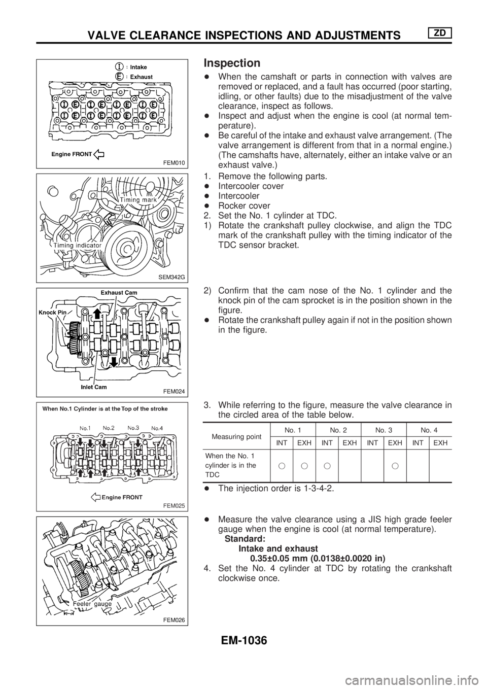
Inspection
+When the camshaft or parts in connection with valves are
removed or replaced, and a fault has occurred (poor starting,
idling, or other faults) due to the misadjustment of the valve
clearance, inspect as follows.
+Inspect and adjust when the engine is cool (at normal tem-
perature).
+Be careful of the intake and exhaust valve arrangement. (The
valve arrangement is different from that in a normal engine.)
(The camshafts have, alternately, either an intake valve or an
exhaust valve.)
1. Remove the following parts.
+Intercooler cover
+Intercooler
+Rocker cover
2. Set the No. 1 cylinder at TDC.
1) Rotate the crankshaft pulley clockwise, and align the TDC
mark of the crankshaft pulley with the timing indicator of the
TDC sensor bracket.
2) Confirm that the cam nose of the No. 1 cylinder and the
knock pin of the cam sprocket is in the position shown in the
figure.
+Rotate the crankshaft pulley again if not in the position shown
in the figure.
3. While referring to the figure, measure the valve clearance in
the circled area of the table below.
Measuring pointNo. 1 No. 2 No. 3 No. 4
INT EXH INT EXH INT EXH INT EXH
When the No. 1
cylinder is in the
TDCjjj j
+The injection order is 1-3-4-2.
+Measure the valve clearance using a JIS high grade feeler
gauge when the engine is cool (at normal temperature).
Standard:
Intake and exhaust
0.35 0.05 mm (0.0138 0.0020 in)
4. Set the No. 4 cylinder at TDC by rotating the crankshaft
clockwise once.
FEM010
SEM342G
FEM024
FEM025
FEM026
VALVE CLEARANCE INSPECTIONS AND ADJUSTMENTSZD
EM-1036
Page 792 of 1033
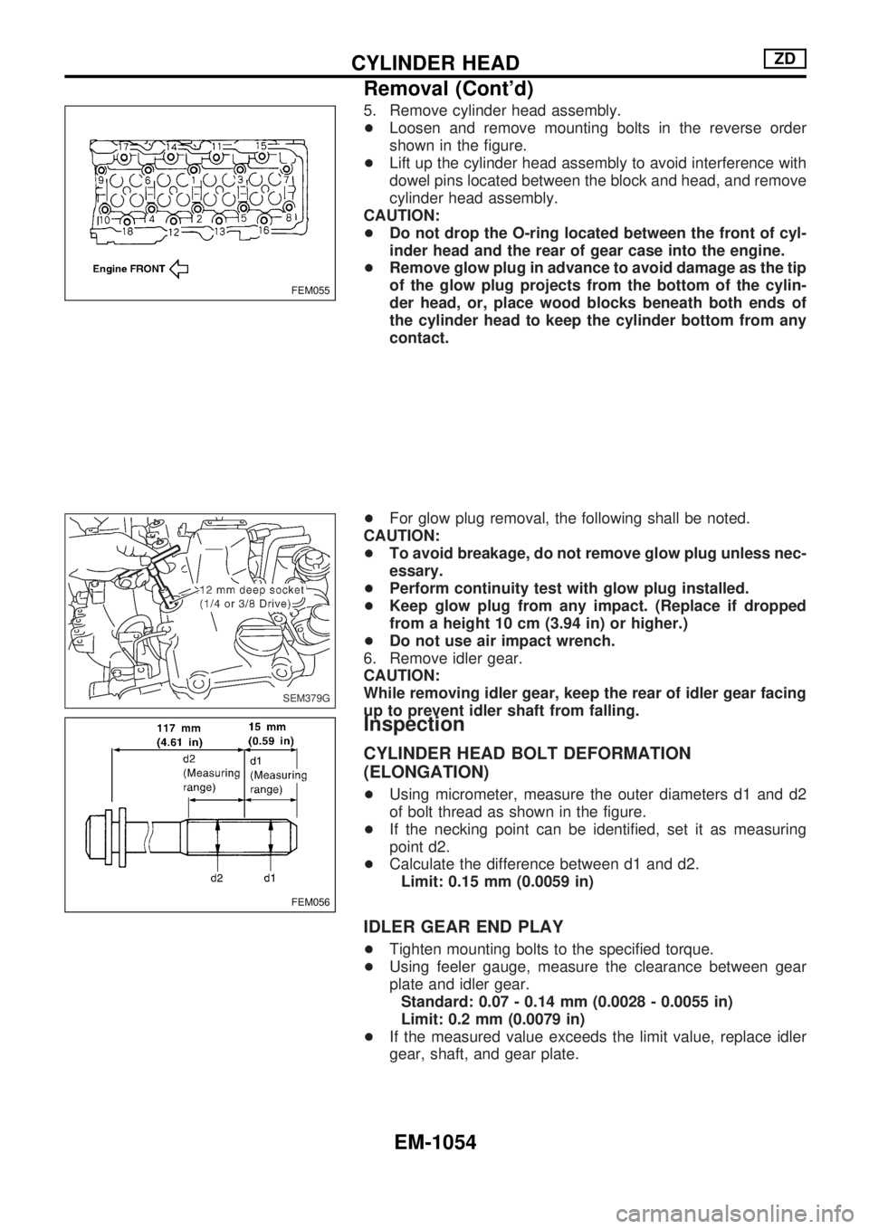
5. Remove cylinder head assembly.
+Loosen and remove mounting bolts in the reverse order
shown in the figure.
+Lift up the cylinder head assembly to avoid interference with
dowel pins located between the block and head, and remove
cylinder head assembly.
CAUTION:
+Do not drop the O-ring located between the front of cyl-
inder head and the rear of gear case into the engine.
+Remove glow plug in advance to avoid damage as the tip
of the glow plug projects from the bottom of the cylin-
der head, or, place wood blocks beneath both ends of
the cylinder head to keep the cylinder bottom from any
contact.
+For glow plug removal, the following shall be noted.
CAUTION:
+To avoid breakage, do not remove glow plug unless nec-
essary.
+Perform continuity test with glow plug installed.
+Keep glow plug from any impact. (Replace if dropped
from a height 10 cm (3.94 in) or higher.)
+Do not use air impact wrench.
6. Remove idler gear.
CAUTION:
While removing idler gear, keep the rear of idler gear facing
up to prevent idler shaft from falling.
Inspection
CYLINDER HEAD BOLT DEFORMATION
(ELONGATION)
+Using micrometer, measure the outer diameters d1 and d2
of bolt thread as shown in the figure.
+If the necking point can be identified, set it as measuring
point d2.
+Calculate the difference between d1 and d2.
Limit: 0.15 mm (0.0059 in)
IDLER GEAR END PLAY
+Tighten mounting bolts to the specified torque.
+Using feeler gauge, measure the clearance between gear
plate and idler gear.
Standard: 0.07 - 0.14 mm (0.0028 - 0.0055 in)
Limit: 0.2 mm (0.0079 in)
+If the measured value exceeds the limit value, replace idler
gear, shaft, and gear plate.
FEM055
SEM379G
FEM056
CYLINDER HEADZD
Removal (Cont'd)
EM-1054
Page 795 of 1033
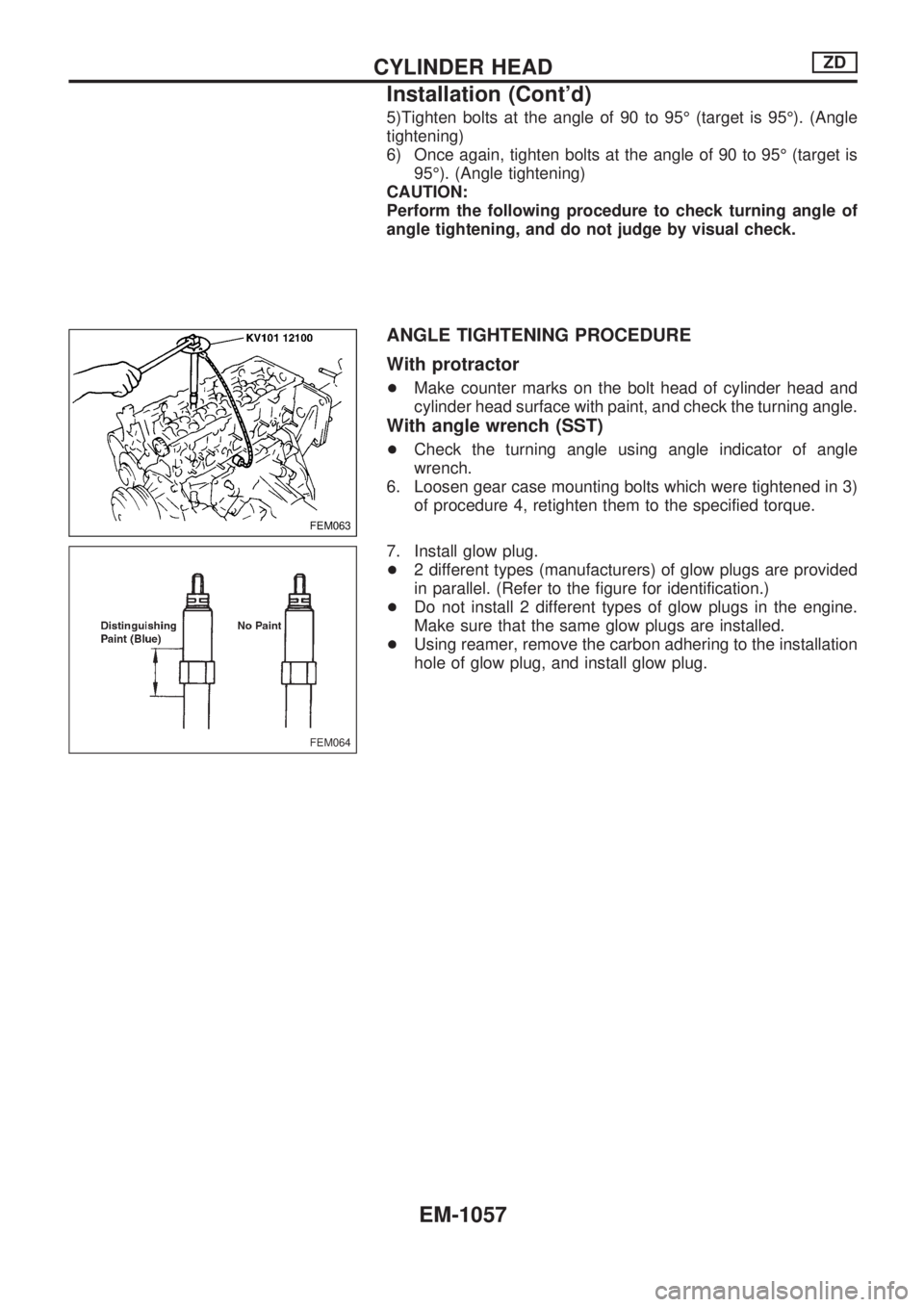
5)Tighten bolts at the angle of 90 to 95É (target is 95É). (Angle
tightening)
6) Once again, tighten bolts at the angle of 90 to 95É (target is
95É). (Angle tightening)
CAUTION:
Perform the following procedure to check turning angle of
angle tightening, and do not judge by visual check.
ANGLE TIGHTENING PROCEDURE
With protractor
+Make counter marks on the bolt head of cylinder head and
cylinder head surface with paint, and check the turning angle.
With angle wrench (SST)
+Check the turning angle using angle indicator of angle
wrench.
6. Loosen gear case mounting bolts which were tightened in 3)
of procedure 4, retighten them to the specified torque.
7. Install glow plug.
+2 different types (manufacturers) of glow plugs are provided
in parallel. (Refer to the figure for identification.)
+Do not install 2 different types of glow plugs in the engine.
Make sure that the same glow plugs are installed.
+Using reamer, remove the carbon adhering to the installation
hole of glow plug, and install glow plug.
FEM063
FEM064
CYLINDER HEADZD
Installation (Cont'd)
EM-1057
Page 800 of 1033
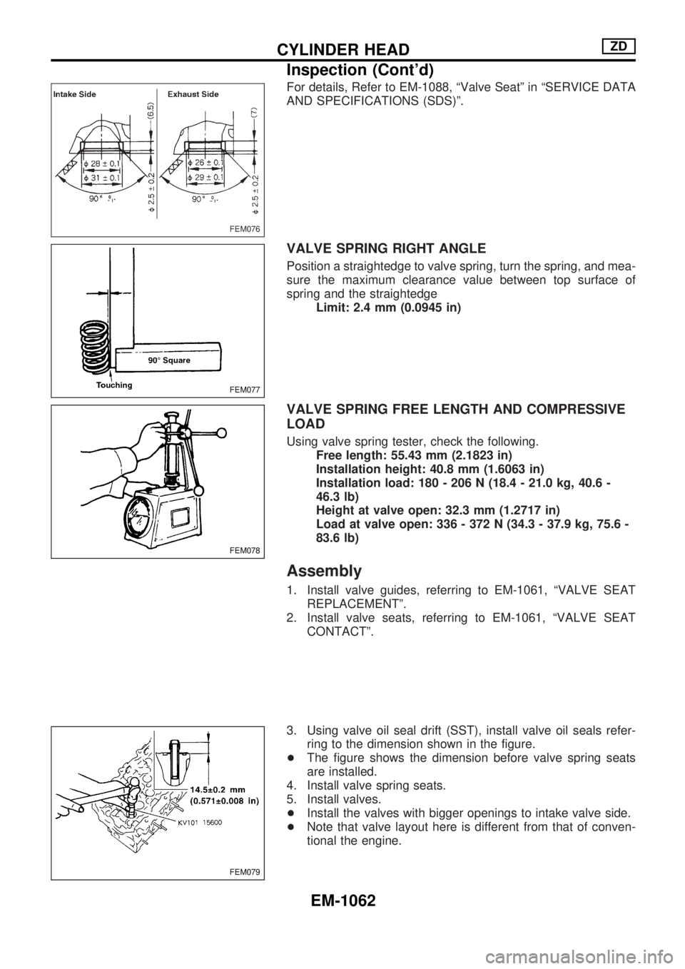
For details, Refer to EM-1088, ªValve Seatº in ªSERVICE DATA
AND SPECIFICATIONS (SDS)º.
VALVE SPRING RIGHT ANGLE
Position a straightedge to valve spring, turn the spring, and mea-
sure the maximum clearance value between top surface of
spring and the straightedge
Limit: 2.4 mm (0.0945 in)
VALVE SPRING FREE LENGTH AND COMPRESSIVE
LOAD
Using valve spring tester, check the following.
Free length: 55.43 mm (2.1823 in)
Installation height: 40.8 mm (1.6063 in)
Installation load: 180 - 206 N (18.4 - 21.0 kg, 40.6 -
46.3 lb)
Height at valve open: 32.3 mm (1.2717 in)
Load at valve open: 336 - 372 N (34.3 - 37.9 kg, 75.6 -
83.6 lb)
Assembly
1. Install valve guides, referring to EM-1061, ªVALVE SEAT
REPLACEMENTº.
2. Install valve seats, referring to EM-1061, ªVALVE SEAT
CONTACTº.
3. Using valve oil seal drift (SST), install valve oil seals refer-
ring to the dimension shown in the figure.
+The figure shows the dimension before valve spring seats
are installed.
4. Install valve spring seats.
5. Install valves.
+Install the valves with bigger openings to intake valve side.
+Note that valve layout here is different from that of conven-
tional the engine.
FEM076
FEM077
FEM078
FEM079
CYLINDER HEADZD
Inspection (Cont'd)
EM-1062
Page 815 of 1033
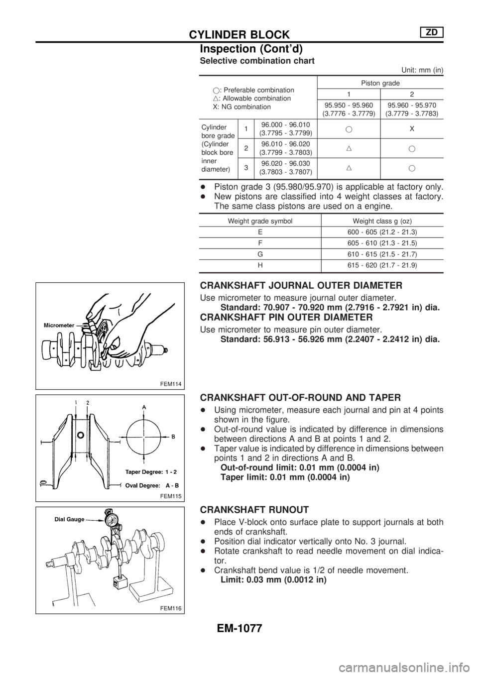
Selective combination chart
Unit: mm (in)
j: Preferable combination
n: Allowable combination
X: NG combinationPiston grade
12
95.950 - 95.960
(3.7776 - 3.7779)95.960 - 95.970
(3.7779 - 3.7783)
Cylinder
bore grade
(Cylinder
block bore
inner
diameter)196.000 - 96.010
(3.7795 - 3.7799)jX
296.010 - 96.020
(3.7799 - 3.7803)nj
396.020 - 96.030
(3.7803 - 3.7807)nj
+Piston grade 3 (95.980/95.970) is applicable at factory only.
+New pistons are classified into 4 weight classes at factory.
The same class pistons are used on a engine.
Weight grade symbol Weight class g (oz)
E 600 - 605 (21.2 - 21.3)
F 605 - 610 (21.3 - 21.5)
G 610 - 615 (21.5 - 21.7)
H 615 - 620 (21.7 - 21.9)
CRANKSHAFT JOURNAL OUTER DIAMETER
Use micrometer to measure journal outer diameter.
Standard: 70.907 - 70.920 mm (2.7916 - 2.7921 in) dia.
CRANKSHAFT PIN OUTER DIAMETER
Use micrometer to measure pin outer diameter.
Standard: 56.913 - 56.926 mm (2.2407 - 2.2412 in) dia.
CRANKSHAFT OUT-OF-ROUND AND TAPER
+Using micrometer, measure each journal and pin at 4 points
shown in the figure.
+Out-of-round value is indicated by difference in dimensions
between directions A and B at points 1 and 2.
+Taper value is indicated by difference in dimensions between
points 1 and 2 in directions A and B.
Out-of-round limit: 0.01 mm (0.0004 in)
Taper limit: 0.01 mm (0.0004 in)
CRANKSHAFT RUNOUT
+Place V-block onto surface plate to support journals at both
ends of crankshaft.
+Position dial indicator vertically onto No. 3 journal.
+Rotate crankshaft to read needle movement on dial indica-
tor.
+Crankshaft bend value is 1/2 of needle movement.
Limit: 0.03 mm (0.0012 in)
FEM114
FEM115
FEM116
CYLINDER BLOCKZD
Inspection (Cont'd)
EM-1077