Page 495 of 1033
ECM Terminals and Reference Value
Specification data are reference values, and are measured between each terminal and ground.
CAUTION:
Do not use ECM ground terminals when measuring input/output voltage. Doing so may damage the
ECM's transistor. Use a ground other than ECM terminals, such as the ground.
TER-
MINAL
NO.WIRE
COLORITEM CONDITION DATA (DC Voltage)
101 R/BVariable nozzle turbo-
charger control solenoid
valveEngine is running.
Warm-up condition
Idle speedApproximately 6.8V
SEF253Z
Engine is running.
Warm-up condition
Engine speed is 2,000 rpmApproximately 11V
SEF254Z
VARIABLE NOZZLE TURBOCHARGER CONTROL
SOLENOID VALVEZD30DDTi
EC-1262
Page 500 of 1033
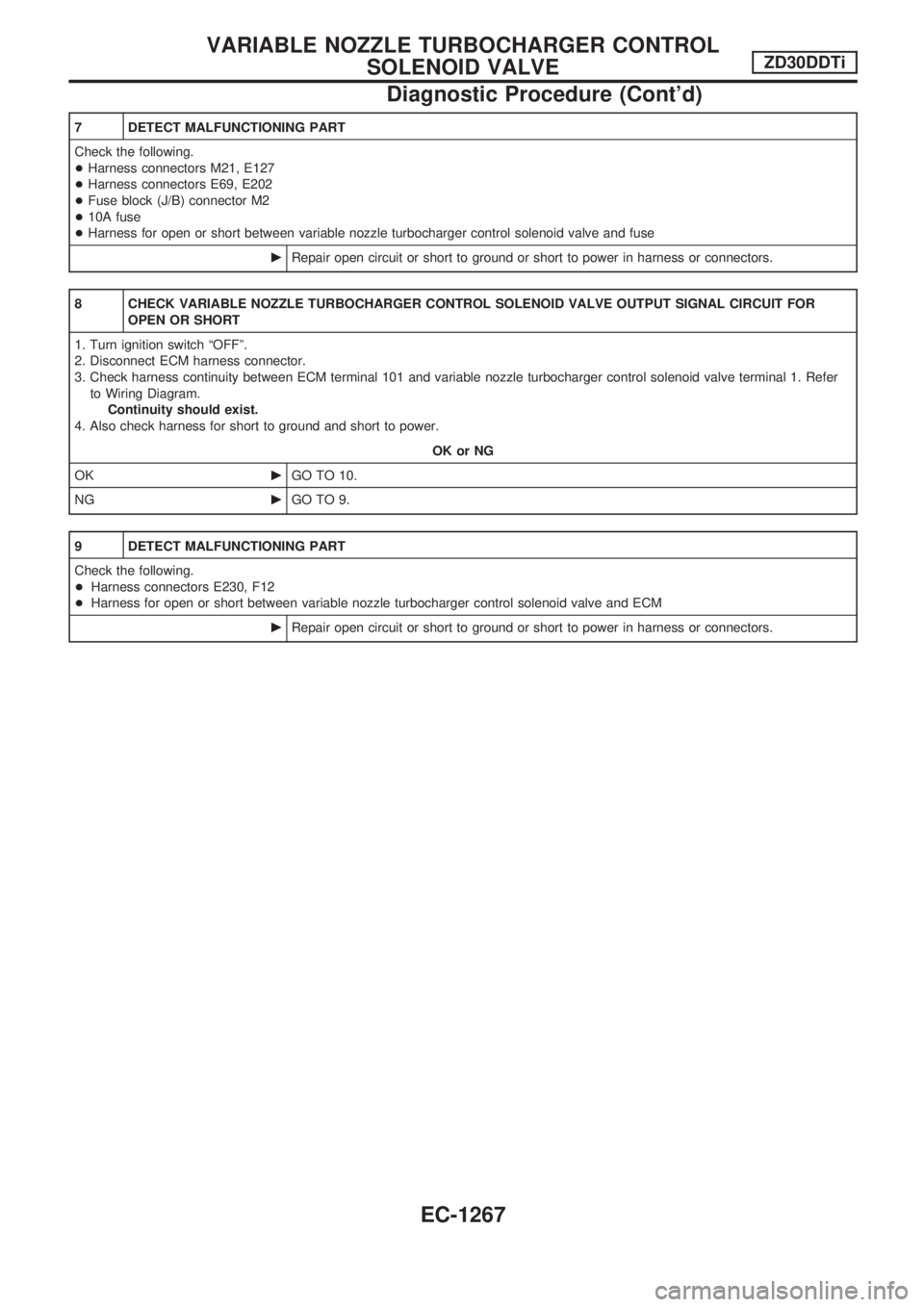
7 DETECT MALFUNCTIONING PART
Check the following.
+Harness connectors M21, E127
+Harness connectors E69, E202
+Fuse block (J/B) connector M2
+10A fuse
+Harness for open or short between variable nozzle turbocharger control solenoid valve and fuse
cRepair open circuit or short to ground or short to power in harness or connectors.
8 CHECK VARIABLE NOZZLE TURBOCHARGER CONTROL SOLENOID VALVE OUTPUT SIGNAL CIRCUIT FOR
OPEN OR SHORT
1. Turn ignition switch ªOFFº.
2. Disconnect ECM harness connector.
3. Check harness continuity between ECM terminal 101 and variable nozzle turbocharger control solenoid valve terminal 1. Refer
to Wiring Diagram.
Continuity should exist.
4. Also check harness for short to ground and short to power.
OK or NG
OKcGO TO 10.
NGcGO TO 9.
9 DETECT MALFUNCTIONING PART
Check the following.
+Harness connectors E230, F12
+Harness for open or short between variable nozzle turbocharger control solenoid valve and ECM
cRepair open circuit or short to ground or short to power in harness or connectors.
VARIABLE NOZZLE TURBOCHARGER CONTROL
SOLENOID VALVEZD30DDTi
Diagnostic Procedure (Cont'd)
EC-1267
Page 502 of 1033
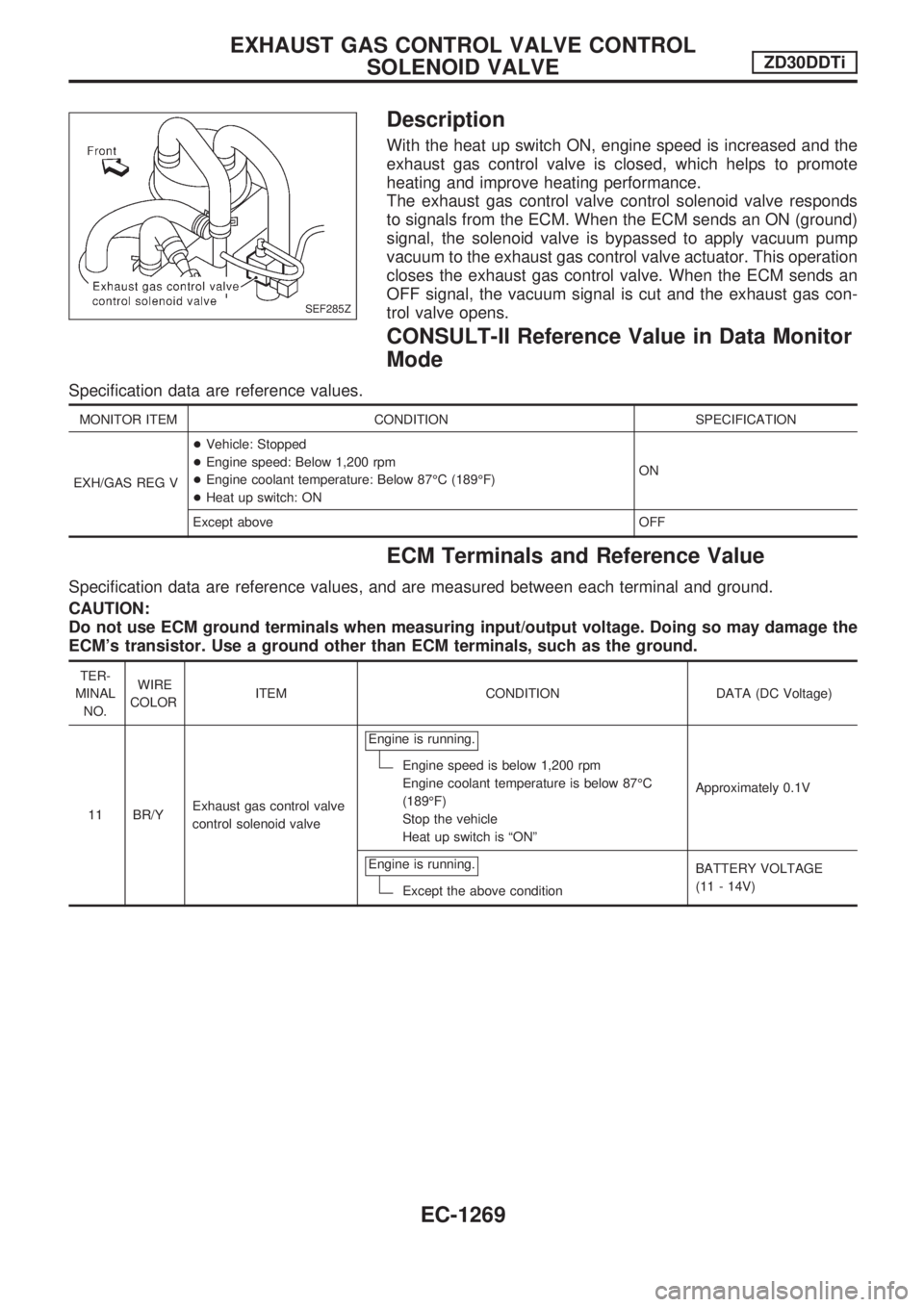
Description
With the heat up switch ON, engine speed is increased and the
exhaust gas control valve is closed, which helps to promote
heating and improve heating performance.
The exhaust gas control valve control solenoid valve responds
to signals from the ECM. When the ECM sends an ON (ground)
signal, the solenoid valve is bypassed to apply vacuum pump
vacuum to the exhaust gas control valve actuator. This operation
closes the exhaust gas control valve. When the ECM sends an
OFF signal, the vacuum signal is cut and the exhaust gas con-
trol valve opens.
CONSULT-II Reference Value in Data Monitor
Mode
Specification data are reference values.
MONITOR ITEM CONDITION SPECIFICATION
EXH/GAS REG V+Vehicle: Stopped
+Engine speed: Below 1,200 rpm
+Engine coolant temperature: Below 87ÉC (189ÉF)
+Heat up switch: ONON
Except above OFF
ECM Terminals and Reference Value
Specification data are reference values, and are measured between each terminal and ground.
CAUTION:
Do not use ECM ground terminals when measuring input/output voltage. Doing so may damage the
ECM's transistor. Use a ground other than ECM terminals, such as the ground.
TER-
MINAL
NO.WIRE
COLORITEM CONDITION DATA (DC Voltage)
11 BR/YExhaust gas control valve
control solenoid valveEngine is running.
Engine speed is below 1,200 rpm
Engine coolant temperature is below 87ÉC
(189ÉF)
Stop the vehicle
Heat up switch is ªONºApproximately 0.1V
Engine is running.
Except the above conditionBATTERY VOLTAGE
(11 - 14V)
SEF285Z
EXHAUST GAS CONTROL VALVE CONTROL
SOLENOID VALVEZD30DDTi
EC-1269
Page 505 of 1033
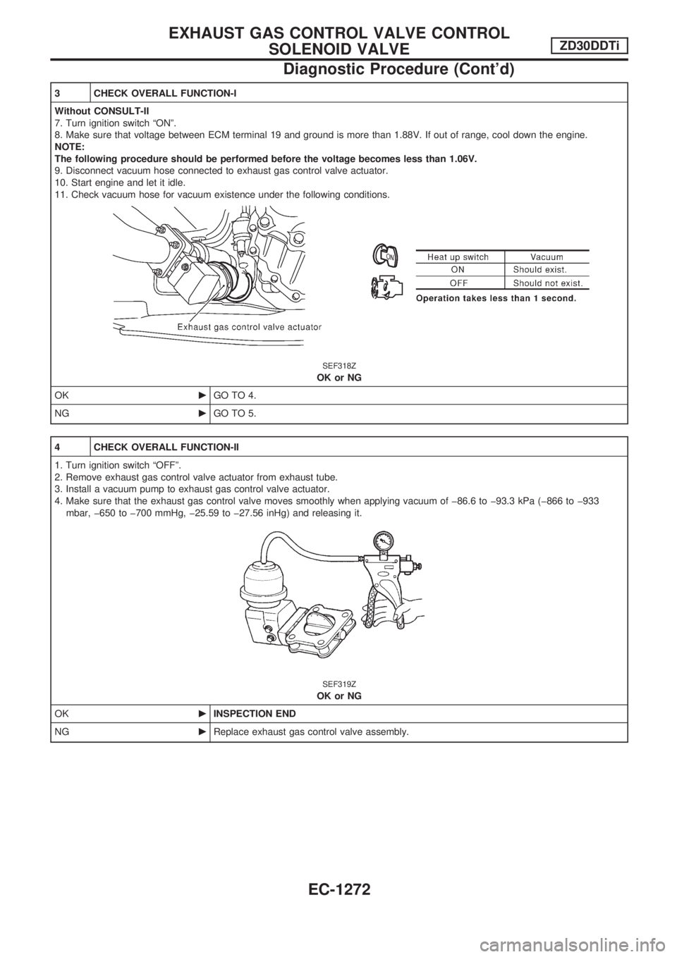
3 CHECK OVERALL FUNCTION-I
Without CONSULT-II
7. Turn ignition switch ªONº.
8. Make sure that voltage between ECM terminal 19 and ground is more than 1.88V. If out of range, cool down the engine.
NOTE:
The following procedure should be performed before the voltage becomes less than 1.06V.
9. Disconnect vacuum hose connected to exhaust gas control valve actuator.
10. Start engine and let it idle.
11. Check vacuum hose for vacuum existence under the following conditions.
SEF318Z
OK or NG
OKcGO TO 4.
NGcGO TO 5.
4 CHECK OVERALL FUNCTION-II
1. Turn ignition switch ªOFFº.
2. Remove exhaust gas control valve actuator from exhaust tube.
3. Install a vacuum pump to exhaust gas control valve actuator.
4. Make sure that the exhaust gas control valve moves smoothly when applying vacuum of þ86.6 to þ93.3 kPa (þ866 to þ933
mbar, þ650 to þ700 mmHg, þ25.59 to þ27.56 inHg) and releasing it.
SEF319Z
OK or NG
OKcINSPECTION END
NGcReplace exhaust gas control valve assembly.
EXHAUST GAS CONTROL VALVE CONTROL
SOLENOID VALVEZD30DDTi
Diagnostic Procedure (Cont'd)
EC-1272
Page 507 of 1033
7 DETECT MALFUNCTIONING PART
Check the following.
+Harness connectors M21, E127
+Fuse block (J/B) connector M2
+10A fuse
+Harness for open or short between exhaust gas control valve control solenoid valve and fuse
cRepair open circuit or short to ground or short to power in harness or connectors.
8 CHECK EXHAUST GAS CONTROL VALVE CONTROL SOLENOID VALVE OUTPUT SIGNAL CIRCUIT FOR OPEN
OR SHORT
1. Turn ignition switch ªOFFº.
2. Disconnect ECM harness connector.
3. Check harness continuity between ECM terminal 11 and exhaust gas control valve control solenoid valve terminal 1. Refer to
Wiring Diagram.
Continuity should exist.
4. Also check harness for short to ground and short to power.
OK or NG
OKcGO TO 10.
NGcGO TO 9.
9 DETECT MALFUNCTIONING PART
Check the following.
+Harness connectors M21, E127
+Harness connectors M50, F5
+Harness for open or short between exhaust gas control valve control solenoid valve and ECM
cRepair open circuit or short to ground or short to power in harness or connectors.
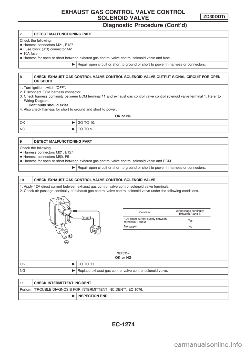
10 CHECK EXHAUST GAS CONTROL VALVE CONTROL SOLENOID VALVE
1. Apply 12V direct current between exhaust gas control valve control solenoid valve terminals.
2. Check air passage continuity of exhaust gas control valve control solenoid valve under the following conditions.
SEF335X
OK or NG
OKcGO TO 11.
NGcReplace exhaust gas control valve control solenoid valve.
11 CHECK INTERMITTENT INCIDENT
Perform ªTROUBLE DIAGNOSIS FOR INTERMITTENT INCIDENTº, EC-1076.
cINSPECTION END
EXHAUST GAS CONTROL VALVE CONTROL
SOLENOID VALVEZD30DDTi
Diagnostic Procedure (Cont'd)
EC-1274
Page 674 of 1033
System Description
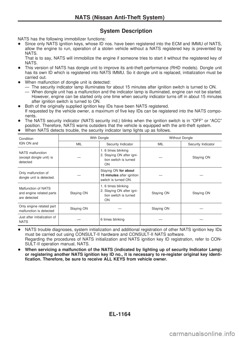
NATS has the following immobilizer functions:
+Since only NATS ignition keys, whose ID nos. have been registered into the ECM and IMMU of NATS,
allow the engine to run, operation of a stolen vehicle without a NATS registered key is prevented by
NATS.
That is to say, NATS will immobilize the engine if someone tries to start it without the registered key of
NATS.
+This version of NATS has dongle unit to improve its anti-theft performance (RHD models). Dongle unit
has its own ID which is registered into NATS IMMU. So it dongle unit is replaced, initialization must be
carried out.
+When malfunction of dongle unit is detected:
Ð The security indicator lamp illuminates for about 15 minutes after ignition switch is turned to ON.
Ð When dongle unit has a malfunction and the indicator lamp is illuminated, engine can not be started.
However, engine can be started only one time when security indicator turns off in about 15 minutes
after ignition switch is turned to ON.
+Both of the originally supplied ignition key IDs have been NATS registered.
If requested by the vehicle owner, a maximum of five key IDs can be registered into the NATS compo-
nents.
+The NATS security indicator (NATS security ind.) blinks when the ignition switch is in ªOFFº or ªACCº
position. Therefore, NATS warns outsiders that the vehicle is equipped with the anti-theft system.
+When NATS detects trouble, the security indicator lamp lights up as follows.
Condition
IGN ON andWith Dongle Without Dongle
MIL Security Indicator MIL Security Indicator
NATS malfunction
(except dongle unit) is
detectedÐ1. 6 times blinking
2. Staying ON after igni-
tion switch is turned
ONÐ Staying ON
Only malfunction of
dongle unit is detected.ÐStaying ONfor about
15 minutesafter ignition
switch is turned ON.ÐÐ
Malfunction of NATS
and engine related parts
are detectedStaying ON1. 6 times blinking
2. Staying ON after igni-
tion switch is turned
ONStaying ON Staying ON
Only engine related part
malfunction is detectedStaying ON Ð Staying ON Ð
Just after initialization of
NATSÐ 6 times blinking Ð Ð
+NATS trouble diagnoses, system initialization and additional registration of other NATS ignition key IDs
must be carried out using CONSULT-II hardware and CONSULT-II NATS software.
Regarding the procedures of NATS initialization and NATS ignition key ID registration, refer to CON-
SULT-II operation manual, NATS.
+When servicing a malfunction of the NATS (indicated by lighting up of security Indicator Lamp)
or registering another NATS ignition key ID no., it is necessary to re-register original key identi-
fication. Therefore, be sure to receive ALL KEYS from vehicle owner.
NATS (Nissan Anti-Theft System)
EL-1164
Page 675 of 1033
System Composition
The immobilizer function of the NATS consists of the following:
+NATS ignition key
+NATS immobilizer control unit (NATS IMMU), located in the ignition key cylinder
+Engine control module (ECM)
+Dongle unit (RHD models)
+NATS security indicator
SEL148XA
NATS (Nissan Anti-Theft System)
EL-1165
Page 680 of 1033
CONSULT-II DIAGNOSTIC TEST MODE FUNCTION
CONSULT-II DIAGNOSTIC TEST
MODEDescription
C/U INITIALIZATION When replacing any of the following components, C/U initialization is necessary.
[NATS ignition key/IMMU/ECM/Dongle unit]
SELF-DIAG RESULTS Detected items (screen terms) are as shown in the chart below.
NOTE:
When any initialization is performed, all ID previously registered will be erased. So all NATS ignition
keys must be registered again.
The engine cannot be started with an unregistered key. In this case, the system may show ªDIFFER-
ENCE OF KEYº or ªLOCK MODEº as a self-diagnostic result on the CONSULT-II screen.
When initialization is performed (for RHD models), security indicator will flash six times to demon-
strate recognition of dongle unit ID.
HOW TO READ SELF-DIAGNOSTIC RESULTS
SEL151X
NATS (Nissan Anti-Theft System)
CONSULT-II (Cont'd)
EL-1170