2000 NISSAN PATROL ecm
[x] Cancel search: ecmPage 681 of 1033
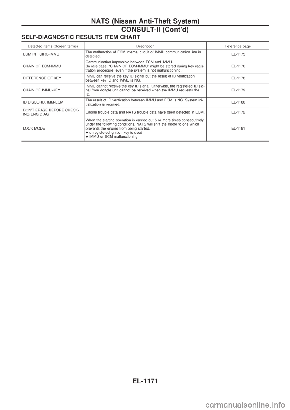
SELF-DIAGNOSTIC RESULTS ITEM CHART
Detected items (Screen terms) Description Reference page
ECM INT CIRC-IMMUThe malfunction of ECM internal circuit of IMMU communication line is
detected.EL-1175
CHAIN OF ECM-IMMUCommunication impossible between ECM and IMMU.
(In rare case, ªCHAIN OF ECM-IMMUº might be stored during key regis-
tration procedure, even if the system is not malfunctioning.)EL-1176
DIFFERENCE OF KEYIMMU can receive the key ID signal but the result of ID verification
between key ID and IMMU is NG.EL-1178
CHAIN OF IMMU-KEYIMMU cannot receive the key ID signal. Otherwise, the registered ID sig-
nal from dongle unit cannot be received when the IMMU requests the
ID.EL-1179
ID DISCORD, IMM-ECMThe result of ID verification between IMMU and ECM is NG. System ini-
tialization is required.EL-1180
DON'T ERASE BEFORE CHECK-
ING ENG DIAGEngine trouble data and NATS trouble data have been detected in ECM. EL-1172
LOCK MODEWhen the starting operation is carried out 5 or more times consecutively
under the following conditions, NATS will shift the mode to one which
prevents the engine from being started.
+unregistered ignition key is used
+IMMU or ECM malfunctioningEL-1181
NATS (Nissan Anti-Theft System)
CONSULT-II (Cont'd)
EL-1171
Page 682 of 1033
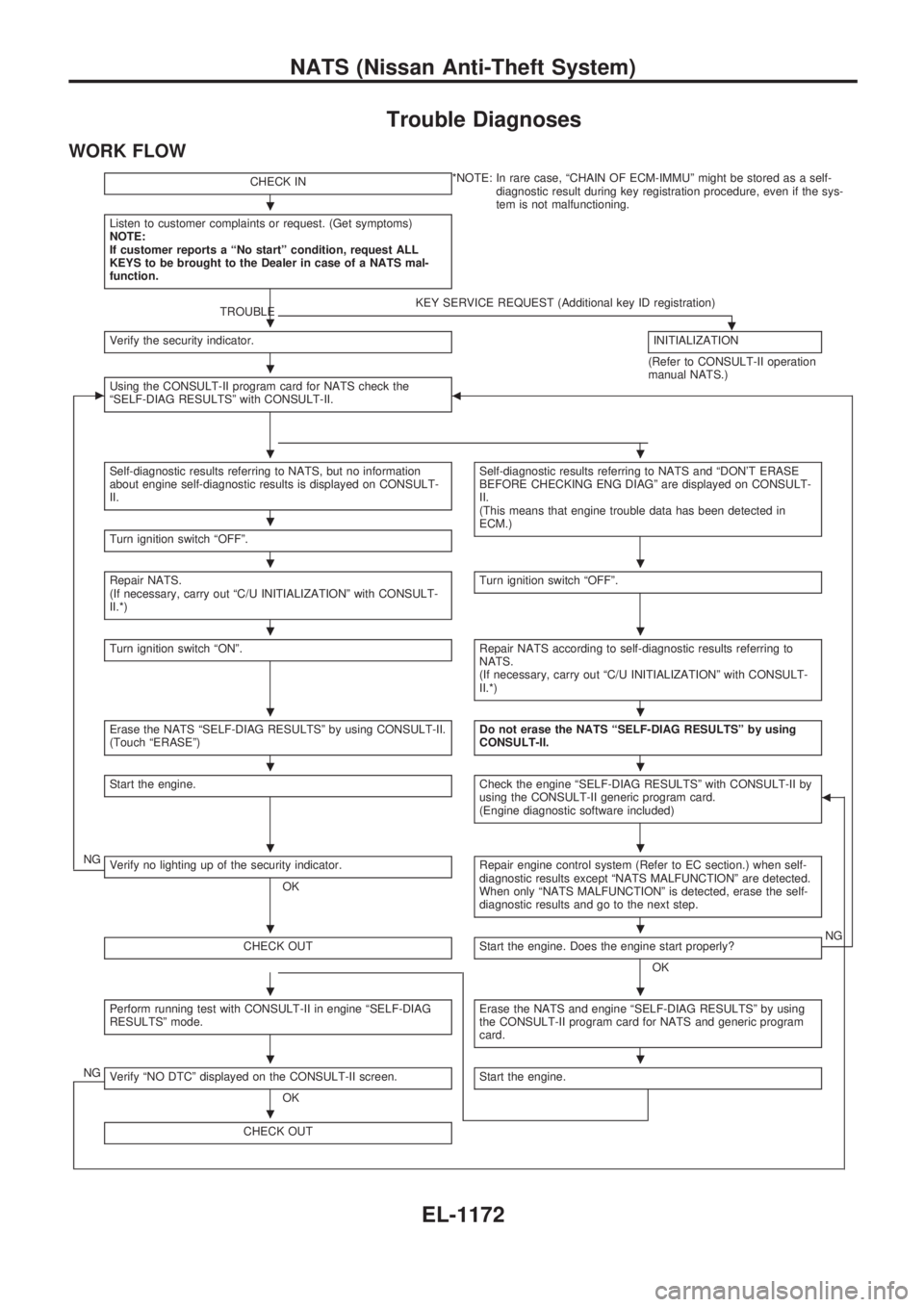
Trouble Diagnoses
WORK FLOW
CHECK IN*NOTE: In rare case, ªCHAIN OF ECM-IMMUº might be stored as a self-
diagnostic result during key registration procedure, even if the sys-
tem is not malfunctioning.
Listen to customer complaints or request. (Get symptoms)
NOTE:
If customer reports a ªNo startº condition, request ALL
KEYS to be brought to the Dealer in case of a NATS mal-
function.
TROUBLEKEY SERVICE REQUEST (Additional key ID registration).Verify the security indicator.INITIALIZATION
(Refer to CONSULT-II operation
manual NATS.)
cUsing the CONSULT-II program card for NATS check the
ªSELF-DIAG RESULTSº with CONSULT-II.b
Self-diagnostic results referring to NATS, but no information
about engine self-diagnostic results is displayed on CONSULT-
II.Self-diagnostic results referring to NATS and ªDON'T ERASE
BEFORE CHECKING ENG DIAGº are displayed on CONSULT-
II.
(This means that engine trouble data has been detected in
ECM.)
Turn ignition switch ªOFFº.
Repair NATS.
(If necessary, carry out ªC/U INITIALIZATIONº with CONSULT-
II.*)Turn ignition switch ªOFFº.
Turn ignition switch ªONº.Repair NATS according to self-diagnostic results referring to
NATS.
(If necessary, carry out ªC/U INITIALIZATIONº with CONSULT-
II.*)
Erase the NATS ªSELF-DIAG RESULTSº by using CONSULT-II.
(Touch ªERASEº)Do not erase the NATS ªSELF-DIAG RESULTSº by using
CONSULT-II.
Start the engine.Check the engine ªSELF-DIAG RESULTSº with CONSULT-II by
using the CONSULT-II generic program card.
(Engine diagnostic software included)b
NGVerify no lighting up of the security indicator.
OKRepair engine control system (Refer to EC section.) when self-
diagnostic results except ªNATS MALFUNCTIONº are detected.
When only ªNATS MALFUNCTIONº is detected, erase the self-
diagnostic results and go to the next step.
CHECK OUTStart the engine. Does the engine start properly?
OKNG
Perform running test with CONSULT-II in engine ªSELF-DIAG
RESULTSº mode.Erase the NATS and engine ªSELF-DIAG RESULTSº by using
the CONSULT-II program card for NATS and generic program
card.
NGVerify ªNO DTCº displayed on the CONSULT-II screen.
OKStart the engine.
CHECK OUT
.
.
.
..
.
..
..
..
..
..
..
..
..
.
NATS (Nissan Anti-Theft System)
EL-1172
Page 683 of 1033
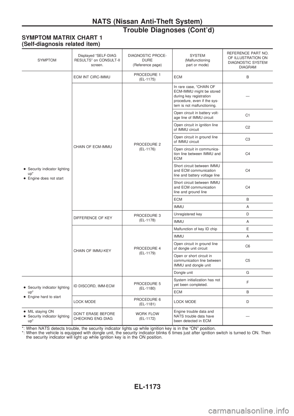
SYMPTOM MATRIX CHART 1
(Self-diagnosis related item)
SYMPTOMDisplayed ªSELF-DIAG
RESULTSº on CONSULT-II
screen.DIAGNOSTIC PROCE-
DURE
(Reference page)SYSTEM
(Malfunctioning
part or mode)REFERENCE PART NO.
OF ILLUSTRATION ON
DIAGNOSTIC SYSTEM
DIAGRAM
+Security indicator lighting
up*
+Engine does not startECM INT CIRC-IMMUPROCEDURE 1
(EL-1175)ECM B
CHAIN OF ECM-IMMUPROCEDURE 2
(EL-1176)In rare case, ªCHAIN OF
ECM-IMMU might be stored
during key registration
procedure, even if the sys-
tem is not malfunctioning.Ð
Open circuit in battery volt-
age line of IMMU circuitC1
Open circuit in ignition line
of IMMU circuitC2
Open circuit in ground line
of IMMU circuitC3
Open circuit in communica-
tion line between IMMU and
ECMC4
Short circuit between IMMU
and ECM communication
line and battery voltage lineC4
Short circuit between IMMU
and ECM communication
line and ground lineC4
ECM B
IMMU A
DIFFERENCE OF KEYPROCEDURE 3
(EL-1178)Unregistered key D
IMMU A
CHAIN OF IMMU-KEYPROCEDURE 4
(EL-1179)Malfunction of key ID chip E
IMMU A
Open circuit in ground line
of dongle unit circuitC6
Open or short circuit in
communication line between
IMMU and dongle unitC5
Dongle unit G
+Security indicator lighting
up*
+Engine hard to startID DISCORD, IMM-ECMPROCEDURE 5
(EL-1180)System initialization has not
yet been completed.F
ECM B
LOCK MODEPROCEDURE 6
(EL-1181)LOCK MODE D
+MIL staying ON
+Security indicator lighting
up*DON'T ERASE BEFORE
CHECKING ENG DIAGWORK FLOW
(EL-1172)Engine trouble data and
NATS trouble data have
been detected in ECMÐ
*: When NATS detects trouble, the security indicator lights up while ignition key is in the ªONº position.
*: When the vehicle is equipped with dongle unit, the security indicator blinks 6 times just after ignition switch is turned to ON. Then
the security indicator will light up while ignition key is in the ON position.
NATS (Nissan Anti-Theft System)
Trouble Diagnoses (Cont'd)
EL-1173
Page 685 of 1033
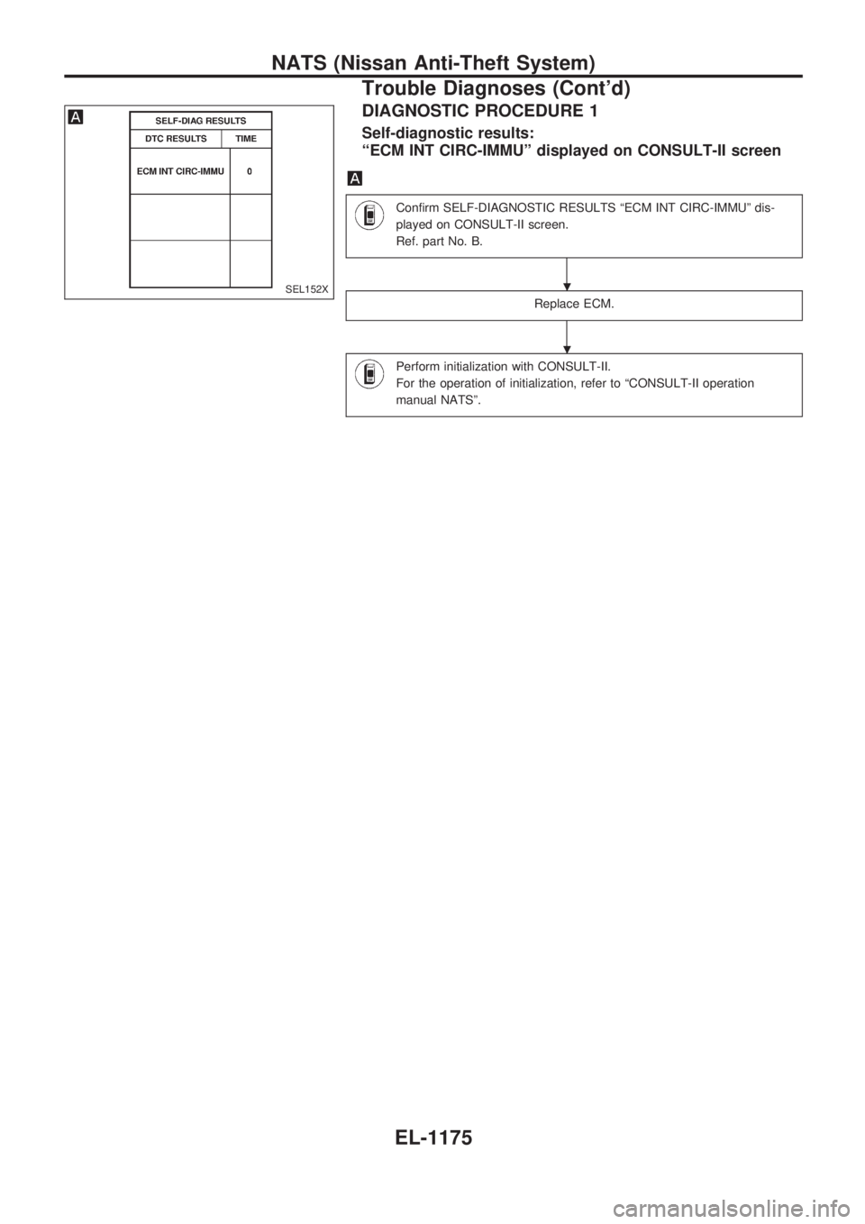
DIAGNOSTIC PROCEDURE 1
Self-diagnostic results:
ªECM INT CIRC-IMMUº displayed on CONSULT-II screen
Confirm SELF-DIAGNOSTIC RESULTS ªECM INT CIRC-IMMUº dis-
played on CONSULT-II screen.
Ref. part No. B.
Replace ECM.
Perform initialization with CONSULT-II.
For the operation of initialization, refer to ªCONSULT-II operation
manual NATSº.
SEL152X.
.
NATS (Nissan Anti-Theft System)
Trouble Diagnoses (Cont'd)
EL-1175
Page 686 of 1033
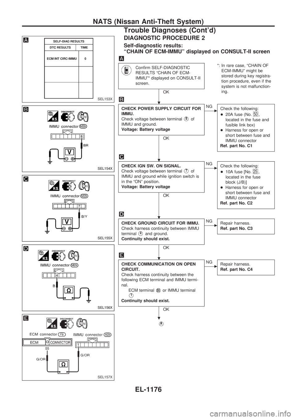
DIAGNOSTIC PROCEDURE 2
Self-diagnostic results:
ªCHAIN OF ECM-IMMUº displayed on CONSULT-II screen
Confirm SELF-DIAGNOSTIC
RESULTS ªCHAIN OF ECM-
IMMUº* displayed on CONSULT-II
screen.
OK*: In rare case, ªCHAIN OF
ECM-IMMUº might be
stored during key registra-
tion procedure, even if the
system is not malfunction-
ing.
CHECK POWER SUPPLY CIRCUIT FOR
IMMU.
Check voltage between terminal
V8of
IMMU and ground.
Voltage: Battery voltage
OK
cNG
Check the following:
+20A fuse (No.
50,
located in the fuse and
fusible link box)
+Harness for open or
short between fuse and
IMMU connector
Ref. part No. C1
CHECK IGN SW. ON SIGNAL.
Check voltage between terminal
V7of
IMMU and ground while ignition switch is
in the ªONº position.
Voltage: Battery voltage
OK
cNG
Check the following:
+10A fuse [No.
25,
located in the fuse
block (J/B)]
+Harness for open or
short between fuse and
IMMU connector
Ref. part No. C2
CHECK GROUND CIRCUIT FOR IMMU.
Check harness continuity between IMMU
terminal
V4and ground.
Continuity should exist.
OK
cNG
Repair harness.
Ref. part No. C3
CHECK COMMUNICATION ON OPEN
CIRCUIT.
Check harness continuity between the
following ECM terminal and IMMU termi-
nal.
ECM terminal
V55or IMMU terminal
V1
Continuity should exist.
OK
cNG
Repair harness.
Ref. part No. C4
VA
SEL153X
SEL154X
SEL155X
SEL156X
SEL157X
.
.
.
.
.
NATS (Nissan Anti-Theft System)
Trouble Diagnoses (Cont'd)
EL-1176
Page 687 of 1033
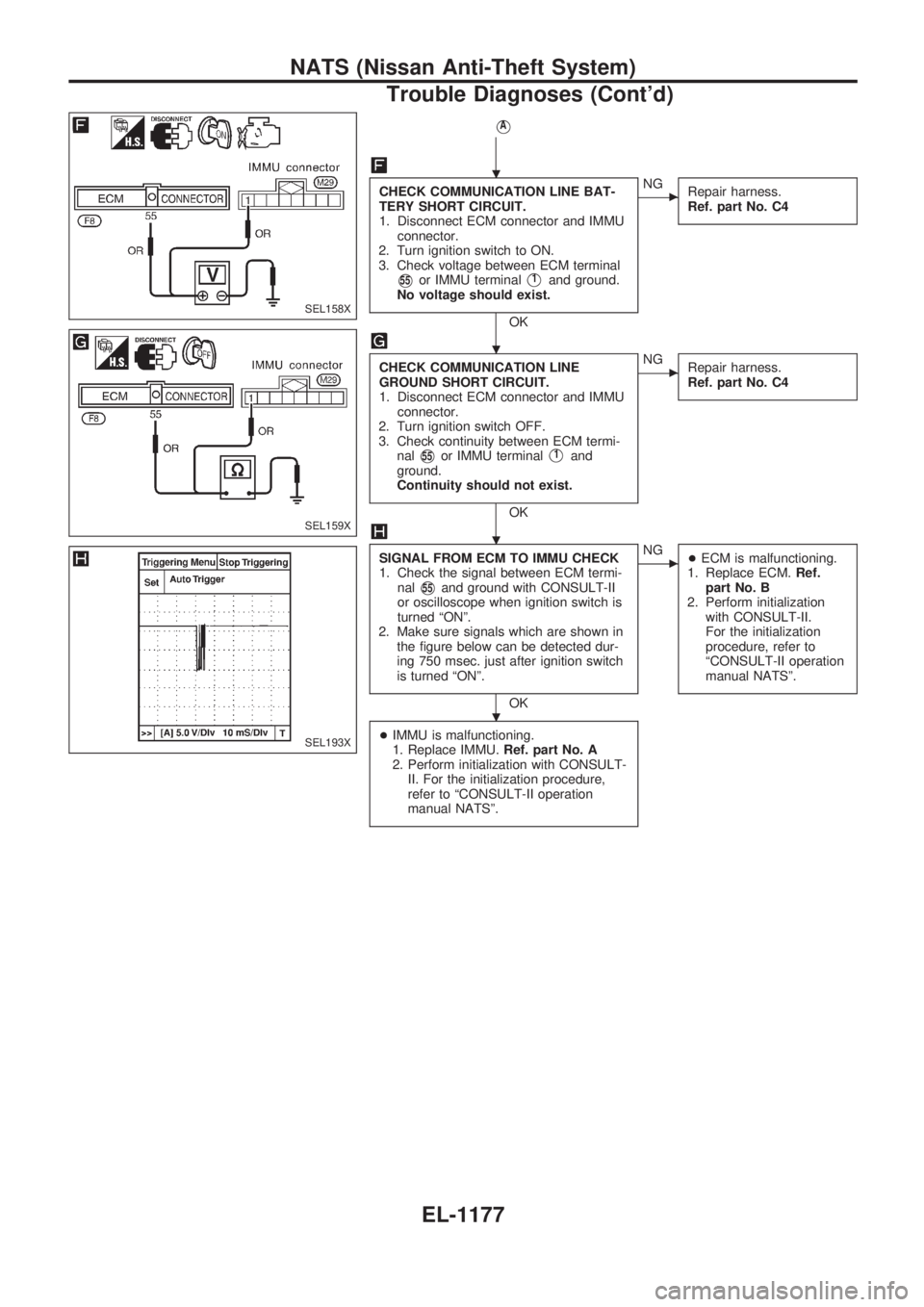
VA
CHECK COMMUNICATION LINE BAT-
TERY SHORT CIRCUIT.
1. Disconnect ECM connector and IMMU
connector.
2. Turn ignition switch to ON.
3. Check voltage between ECM terminal
V55or IMMU terminalV1and ground.
No voltage should exist.
OK
cNG
Repair harness.
Ref. part No. C4
CHECK COMMUNICATION LINE
GROUND SHORT CIRCUIT.
1. Disconnect ECM connector and IMMU
connector.
2. Turn ignition switch OFF.
3. Check continuity between ECM termi-
nal
V55or IMMU terminalV1and
ground.
Continuity should not exist.
OK
cNG
Repair harness.
Ref. part No. C4
SIGNAL FROM ECM TO IMMU CHECK
1. Check the signal between ECM termi-
nal
V55and ground with CONSULT-II
or oscilloscope when ignition switch is
turned ªONº.
2. Make sure signals which are shown in
the figure below can be detected dur-
ing 750 msec. just after ignition switch
is turned ªONº.
OK
cNG
+ECM is malfunctioning.
1. Replace ECM.Ref.
part No. B
2. Perform initialization
with CONSULT-II.
For the initialization
procedure, refer to
ªCONSULT-II operation
manual NATSº.
+IMMU is malfunctioning.
1. Replace IMMU.Ref. part No. A
2. Perform initialization with CONSULT-
II. For the initialization procedure,
refer to ªCONSULT-II operation
manual NATSº.
SEL158X
SEL159X
SEL193X
.
.
.
.
NATS (Nissan Anti-Theft System)
Trouble Diagnoses (Cont'd)
EL-1177
Page 690 of 1033
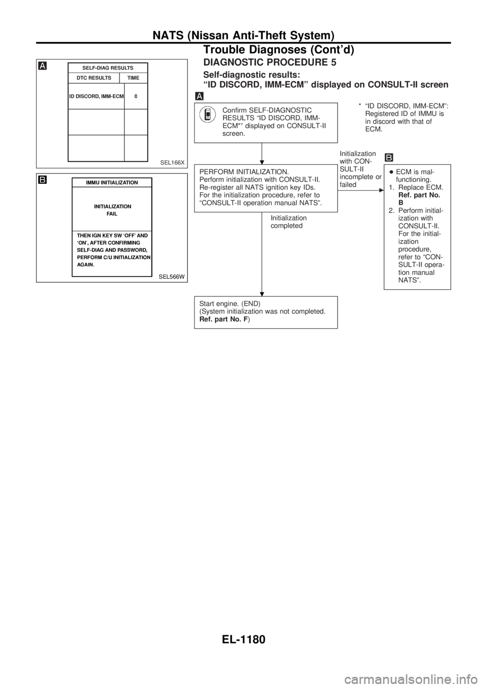
DIAGNOSTIC PROCEDURE 5
Self-diagnostic results:
ªID DISCORD, IMM-ECMº displayed on CONSULT-II screen
Confirm SELF-DIAGNOSTIC
RESULTS ªID DISCORD, IMM-
ECM*º displayed on CONSULT-II
screen.* ªID DISCORD, IMM-ECMº:
Registered ID of IMMU is
in discord with that of
ECM.
PERFORM INITIALIZATION.
Perform initialization with CONSULT-II.
Re-register all NATS ignition key IDs.
For the initialization procedure, refer to
ªCONSULT-II operation manual NATSº.
Initialization
completedInitialization
with CON-
SULT-II
incomplete or
failed
c
+ECM is mal-
functioning.
1. Replace ECM.
Ref. part No.
B
2. Perform initial-
ization with
CONSULT-II.
For the initial-
ization
procedure,
refer to ªCON-
SULT-II opera-
tion manual
NATSº.
Start engine. (END)
(System initialization was not completed.
Ref. part No. F)
SEL166X
SEL566W
.
.
NATS (Nissan Anti-Theft System)
Trouble Diagnoses (Cont'd)
EL-1180
Page 737 of 1033
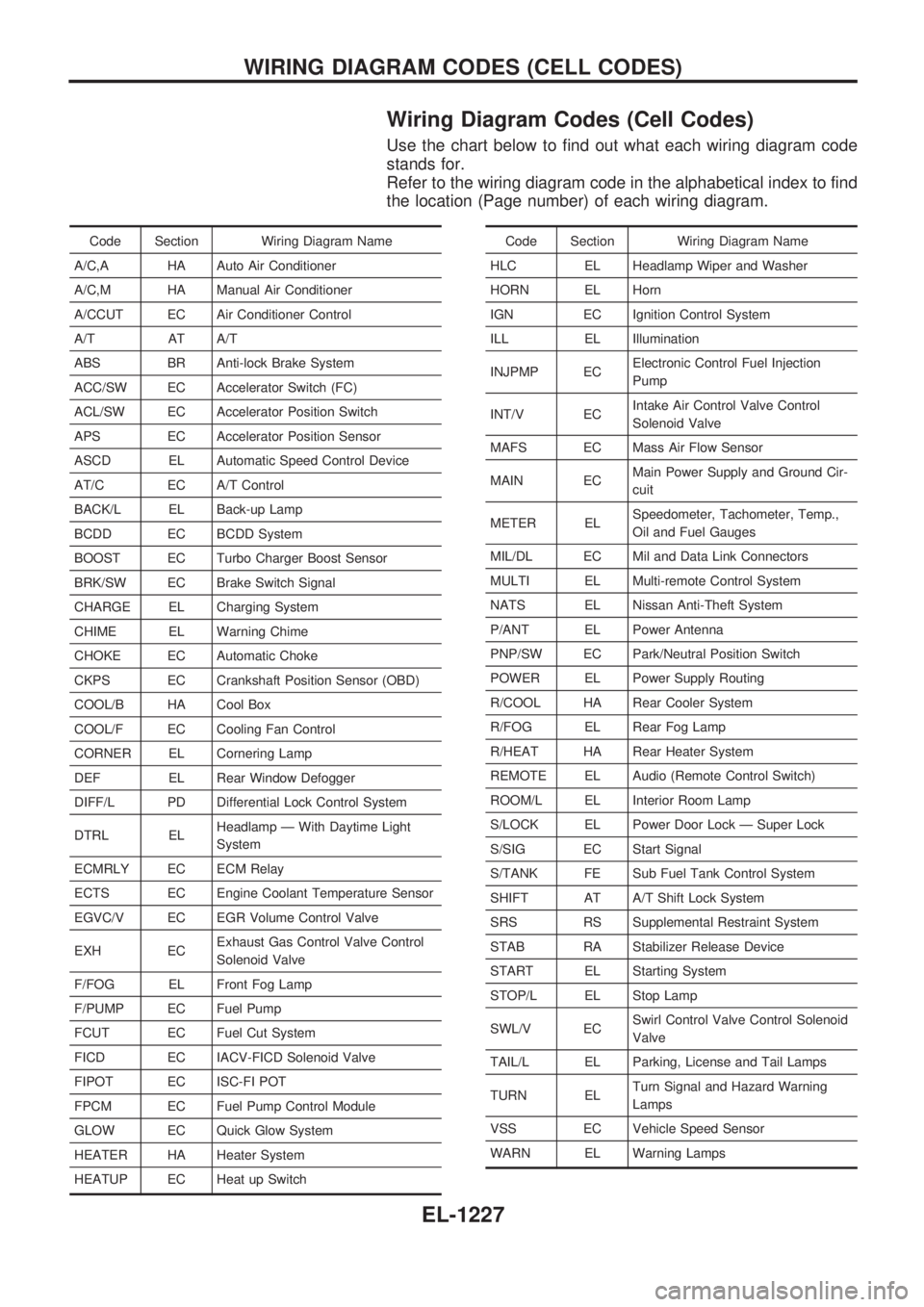
Wiring Diagram Codes (Cell Codes)
Use the chart below to find out what each wiring diagram code
stands for.
Refer to the wiring diagram code in the alphabetical index to find
the location (Page number) of each wiring diagram.
Code Section Wiring Diagram Name
A/C,A HA Auto Air Conditioner
A/C,M HA Manual Air Conditioner
A/CCUT EC Air Conditioner Control
A/T AT A/T
ABS BR Anti-lock Brake System
ACC/SW EC Accelerator Switch (FC)
ACL/SW EC Accelerator Position Switch
APS EC Accelerator Position Sensor
ASCD EL Automatic Speed Control Device
AT/C EC A/T Control
BACK/L EL Back-up Lamp
BCDD EC BCDD System
BOOST EC Turbo Charger Boost Sensor
BRK/SW EC Brake Switch Signal
CHARGE EL Charging System
CHIME EL Warning Chime
CHOKE EC Automatic Choke
CKPS EC Crankshaft Position Sensor (OBD)
COOL/B HA Cool Box
COOL/F EC Cooling Fan Control
CORNER EL Cornering Lamp
DEF EL Rear Window Defogger
DIFF/L PD Differential Lock Control System
DTRL ELHeadlamp Ð With Daytime Light
System
ECMRLY EC ECM Relay
ECTS EC Engine Coolant Temperature Sensor
EGVC/V EC EGR Volume Control Valve
EXH ECExhaust Gas Control Valve Control
Solenoid Valve
F/FOG EL Front Fog Lamp
F/PUMP EC Fuel Pump
FCUT EC Fuel Cut System
FICD EC IACV-FICD Solenoid Valve
FIPOT EC ISC-FI POT
FPCM EC Fuel Pump Control Module
GLOW EC Quick Glow System
HEATER HA Heater System
HEATUP EC Heat up SwitchCode Section Wiring Diagram Name
HLC EL Headlamp Wiper and Washer
HORN EL Horn
IGN EC Ignition Control System
ILL EL Illumination
INJPMP ECElectronic Control Fuel Injection
Pump
INT/V ECIntake Air Control Valve Control
Solenoid Valve
MAFS EC Mass Air Flow Sensor
MAIN ECMain Power Supply and Ground Cir-
cuit
METER ELSpeedometer, Tachometer, Temp.,
Oil and Fuel Gauges
MIL/DL EC Mil and Data Link Connectors
MULTI EL Multi-remote Control System
NATS EL Nissan Anti-Theft System
P/ANT EL Power Antenna
PNP/SW EC Park/Neutral Position Switch
POWER EL Power Supply Routing
R/COOL HA Rear Cooler System
R/FOG EL Rear Fog Lamp
R/HEAT HA Rear Heater System
REMOTE EL Audio (Remote Control Switch)
ROOM/L EL Interior Room Lamp
S/LOCK EL Power Door Lock Ð Super Lock
S/SIG EC Start Signal
S/TANK FE Sub Fuel Tank Control System
SHIFT AT A/T Shift Lock System
SRS RS Supplemental Restraint System
STAB RA Stabilizer Release Device
START EL Starting System
STOP/L EL Stop Lamp
SWL/V ECSwirl Control Valve Control Solenoid
Valve
TAIL/L EL Parking, License and Tail Lamps
TURN ELTurn Signal and Hazard Warning
Lamps
VSS EC Vehicle Speed Sensor
WARN EL Warning Lamps
WIRING DIAGRAM CODES (CELL CODES)
EL-1227