2000 NISSAN PATROL engine oil
[x] Cancel search: engine oilPage 61 of 1033
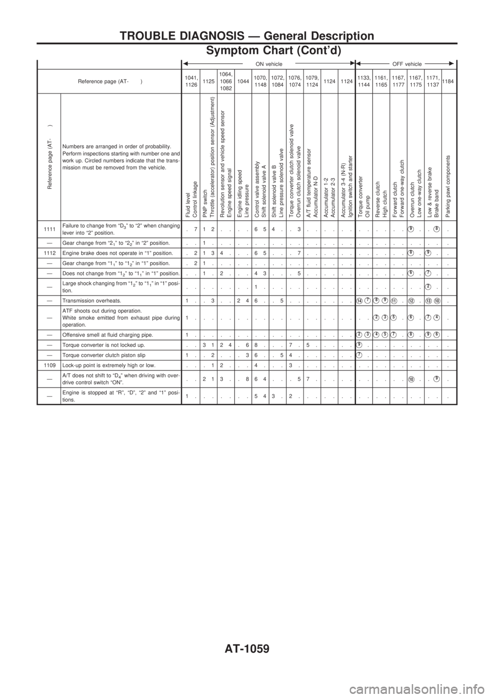
bON vehiclecbOFF vehiclec
Reference page (AT- )1041,
112611251064,
1066
108210441070,
11481072,
10841076,
10741079,
11241124 11241133,
11441161,
11651167,
11771167,
11751171,
11371184
Reference page (AT- )
Numbers are arranged in order of probability.
Perform inspections starting with number one and
work up. Circled numbers indicate that the trans-
mission must be removed from the vehicle.
Fluid level
Control linkage
PNP switch
Throttle (accelerator) position sensor (Adjustment)
Revolution sensor and vehicle speed sensor
Engine speed signal
Engine idling speed
Line pressure
Control valve assembly
Shift solenoid valve A
Shift solenoid valve B
Line pressure solenoid valve
Torque converter clutch solenoid valve
Overrun clutch solenoid valve
A/T fluid temperature sensor
Accumulator N-D
Accumulator 1-2
Accumulator 2-3
Accumulator 3-4 (N-R)
Ignition switch and starter
Torque converter
Oil pump
Reverse clutch
High clutch
Forward clutch
Forward one-way clutch
Overrun clutch
Low one-way clutch
Low & reverse brake
Brake band
Parking pawl components
1111Failure to change from ªD3º to ª2º when changing
lever into ª2º position..712....654..3............V9..V8.
Ð Gear change from ª2
1ºtoª22º in ª2º position. . . 1........................... .
1112 Engine brake does not operate in ª1º position. .2134 . . . 65 . . . 7............
V8.V9..
Ð Gear change from ª1
1ºtoª12º in ª1º position. . 2 1........................... .
Ð Does not change from ª1
2ºtoª11º in ª1º position. ..1.2. . .43. . .5............V6.V7..
ÐLarge shock changing from ª1
2ºtoª11º in ª1º posi-
tion.........1...................V2..
Ð Transmission overheats. 1 . . 3 . . 2 4 6 . . 5........
V14V7V8V9V11.V12.V13V10.
ÐATF shoots out during operation.
White smoke emitted from exhaust pipe during
operation.1.....................
V2V3V5.V6.V7V4.
Ð Offensive smell at fluid charging pipe. 1...................
V2V3V4V5V7.V8.V9V6.
Ð Torque converter is not locked up. . .3124.68. . .7.5.....
V9......... .
Ð Torque converter clutch piston slip 1 . . 2 . . . 3 6 . . 5 4.......
V7......... .
1109 Lock-up point is extremely high or low. . . . 1 2 . . . 4 . . . 3................. .
ÐA/T does not shift to ªD
4º when driving with over-
drive control switch ªONº...213..864...57...........V10..V9.
ÐEngine is stopped at ªRº, ªDº, ª2º and ª1º posi-
tions.1.......543.2................. .
TROUBLE DIAGNOSIS Ð General Description
Symptom Chart (Cont'd)
AT-1059
Page 79 of 1033
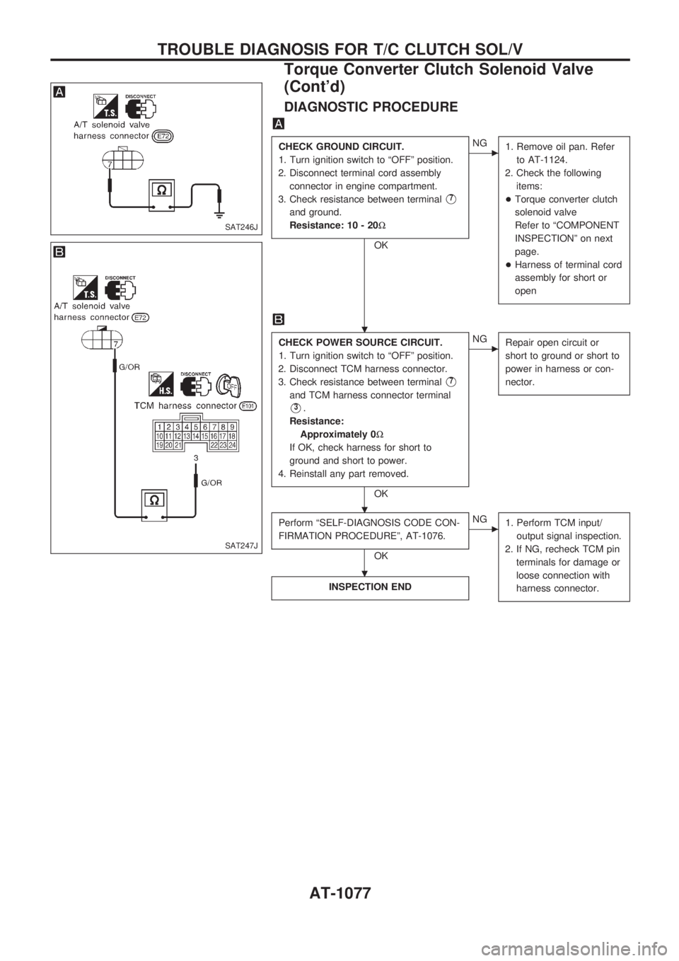
DIAGNOSTIC PROCEDURE
CHECK GROUND CIRCUIT.
1. Turn ignition switch to ªOFFº position.
2. Disconnect terminal cord assembly
connector in engine compartment.
3. Check resistance between terminal
V7
and ground.
Resistance: 10 - 20W
OK
cNG
1. Remove oil pan. Refer
to AT-1124.
2. Check the following
items:
+Torque converter clutch
solenoid valve
Refer to ªCOMPONENT
INSPECTIONº on next
page.
+Harness of terminal cord
assembly for short or
open
CHECK POWER SOURCE CIRCUIT.
1. Turn ignition switch to ªOFFº position.
2. Disconnect TCM harness connector.
3. Check resistance between terminal
V7
and TCM harness connector terminal
V3.
Resistance:
Approximately 0W
If OK, check harness for short to
ground and short to power.
4. Reinstall any part removed.
OK
cNG
Repair open circuit or
short to ground or short to
power in harness or con-
nector.
Perform ªSELF-DIAGNOSIS CODE CON-
FIRMATION PROCEDUREº, AT-1076.
OK
cNG
1. Perform TCM input/
output signal inspection.
2. If NG, recheck TCM pin
terminals for damage or
loose connection with
harness connector.
INSPECTION END
SAT246J
SAT247J
.
.
.
TROUBLE DIAGNOSIS FOR T/C CLUTCH SOL/V
Torque Converter Clutch Solenoid Valve
(Cont'd)
AT-1077
Page 82 of 1033
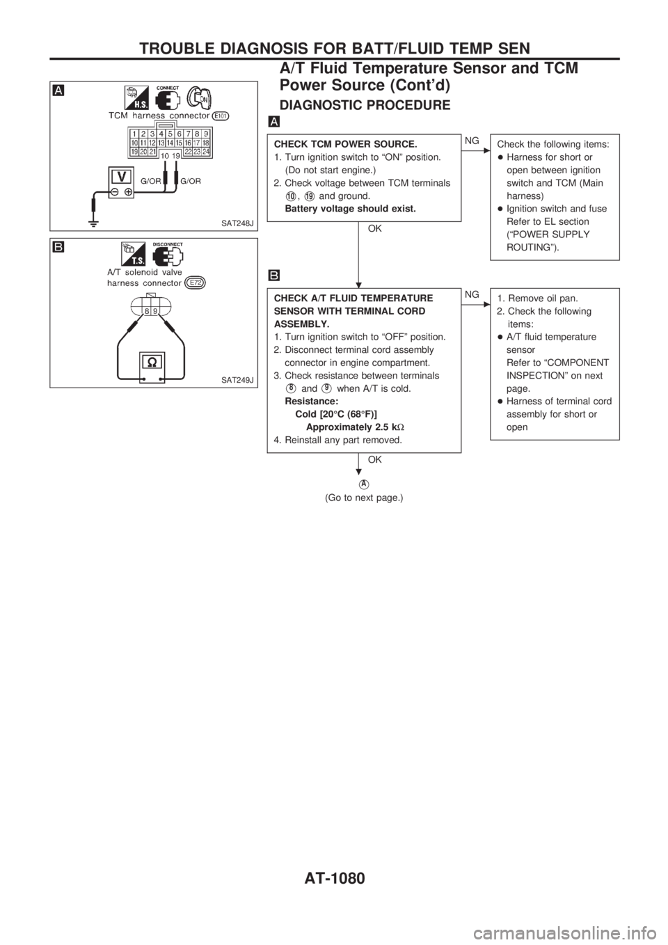
DIAGNOSTIC PROCEDURE
CHECK TCM POWER SOURCE.
1. Turn ignition switch to ªONº position.
(Do not start engine.)
2. Check voltage between TCM terminals
V10,V19and ground.
Battery voltage should exist.
OK
cNG
Check the following items:
+Harness for short or
open between ignition
switch and TCM (Main
harness)
+Ignition switch and fuse
Refer to EL section
(ªPOWER SUPPLY
ROUTINGº).
CHECK A/T FLUID TEMPERATURE
SENSOR WITH TERMINAL CORD
ASSEMBLY.
1. Turn ignition switch to ªOFFº position.
2. Disconnect terminal cord assembly
connector in engine compartment.
3. Check resistance between terminals
V8andV9when A/T is cold.
Resistance:
Cold [20ÉC (68ÉF)]
Approximately 2.5 kW
4. Reinstall any part removed.
OK
cNG
1. Remove oil pan.
2. Check the following
items:
+A/T fluid temperature
sensor
Refer to ªCOMPONENT
INSPECTIONº on next
page.
+Harness of terminal cord
assembly for short or
open
VA
(Go to next page.)
SAT248J
SAT249J
.
.
TROUBLE DIAGNOSIS FOR BATT/FLUID TEMP SEN
A/T Fluid Temperature Sensor and TCM
Power Source (Cont'd)
AT-1080
Page 85 of 1033
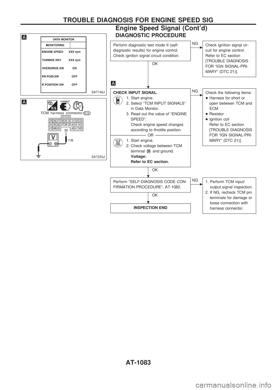
DIAGNOSTIC PROCEDURE
Perform diagnostic test mode II (self-
diagnostic results) for engine control.
Check ignition signal circuit condition.
OK
cNG
Check ignition signal cir-
cuit for engine control.
Refer to EC section
[TROUBLE DIAGNOSIS
FOR ªIGN SIGNAL-PRI-
MARYº (DTC 21)].
CHECK INPUT SIGNAL.
1. Start engine.
2. Select ªTCM INPUT SIGNALSº
in Data Monitor.
3. Read out the value of ªENGINE
SPEEDº.
Check engine speed changes
according to throttle position.
------------------------------------------------------------------------------------------------------------------------------------OR------------------------------------------------------------------------------------------------------------------------------------
1. Start engine.
2. Check voltage between TCM
terminal
V39and ground.
Voltage:
Refer to EC section.
OK
cNG
Check the following items:
+Harness for short or
open between TCM and
ECM
+Resistor
+Ignition coil
Refer to EC section
[TROUBLE DIAGNOSIS
FOR ªIGN SIGNAL-PRI-
MARYº (DTC 21)].
Perform ªSELF-DIAGNOSIS CODE CON-
FIRMATION PROCEDUREº, AT-1082.
OK
cNG
1. Perform TCM input/
output signal inspection.
2. If NG, recheck TCM pin
terminals for damage or
loose connection with
harness connector.
INSPECTION END
SAT740J
SAT253J
.
.
.
TROUBLE DIAGNOSIS FOR ENGINE SPEED SIG
Engine Speed Signal (Cont'd)
AT-1083
Page 86 of 1033
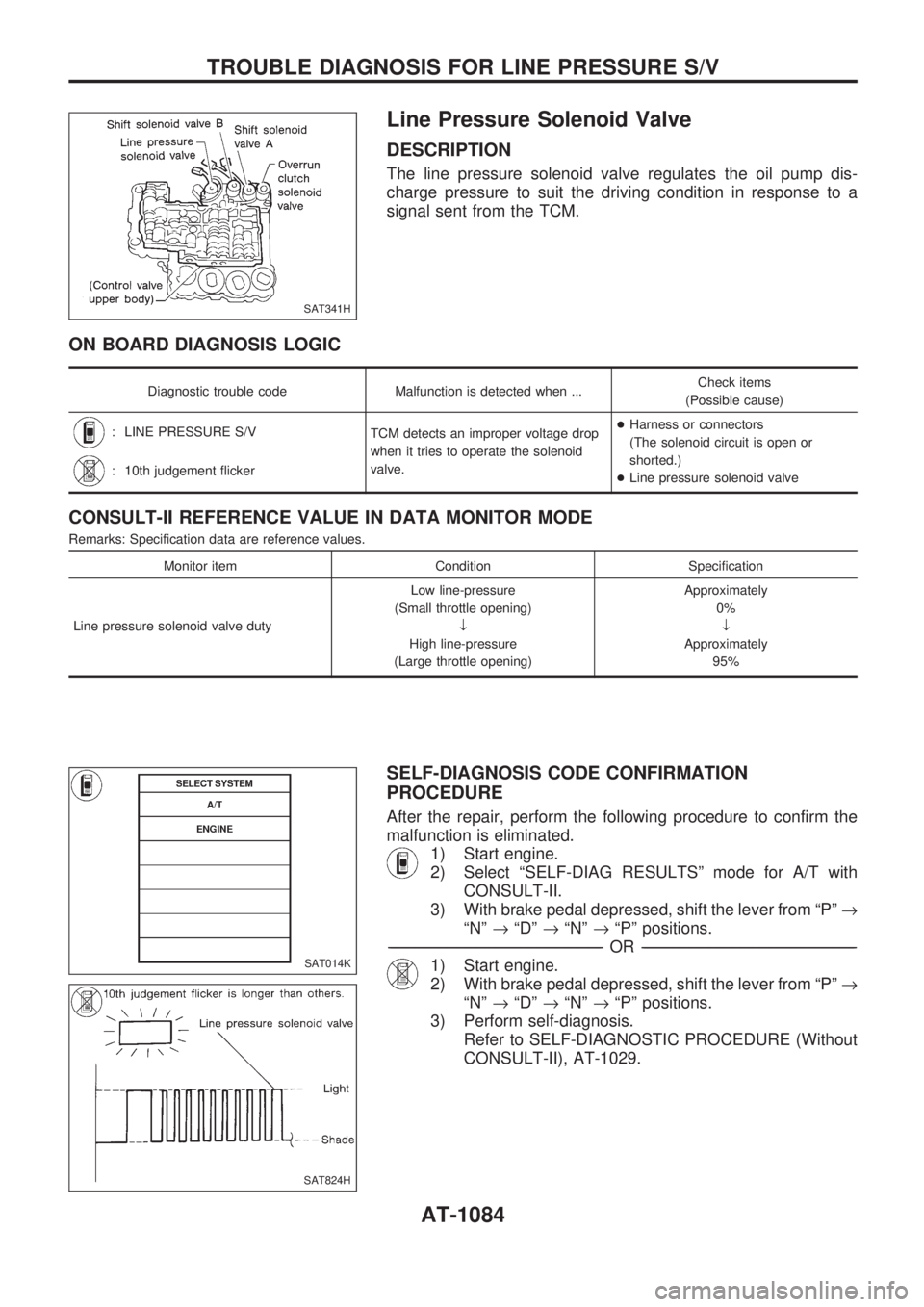
Line Pressure Solenoid Valve
DESCRIPTION
The line pressure solenoid valve regulates the oil pump dis-
charge pressure to suit the driving condition in response to a
signal sent from the TCM.
ON BOARD DIAGNOSIS LOGIC
Diagnostic trouble code Malfunction is detected when ...Check items
(Possible cause)
: LINE PRESSURE S/V
TCM detects an improper voltage drop
when it tries to operate the solenoid
valve.+Harness or connectors
(The solenoid circuit is open or
shorted.)
+Line pressure solenoid valve
: 10th judgement flicker
CONSULT-II REFERENCE VALUE IN DATA MONITOR MODE
Remarks: Specification data are reference values.
Monitor item Condition Specification
Line pressure solenoid valve dutyLow line-pressure
(Small throttle opening)
¯
High line-pressure
(Large throttle opening)Approximately
0%
¯
Approximately
95%
SELF-DIAGNOSIS CODE CONFIRMATION
PROCEDURE
After the repair, perform the following procedure to confirm the
malfunction is eliminated.
1) Start engine.
2) Select ªSELF-DIAG RESULTSº mode for A/T with
CONSULT-II.
3) With brake pedal depressed, shift the lever from ªPº®
ªNº®ªDº®ªNº®ªPº positions.
-------------------------------------------------------------------------------------------------------------------------------------------------------------------------------------------------------------------------------------------------OR-------------------------------------------------------------------------------------------------------------------------------------------------------------------------------------------------------------------------------------------------
1) Start engine.
2) With brake pedal depressed, shift the lever from ªPº®
ªNº®ªDº®ªNº®ªPº positions.
3) Perform self-diagnosis.
Refer to SELF-DIAGNOSTIC PROCEDURE (Without
CONSULT-II), AT-1029.
SAT341H
SAT014K
SAT824H
TROUBLE DIAGNOSIS FOR LINE PRESSURE S/V
AT-1084
Page 112 of 1033
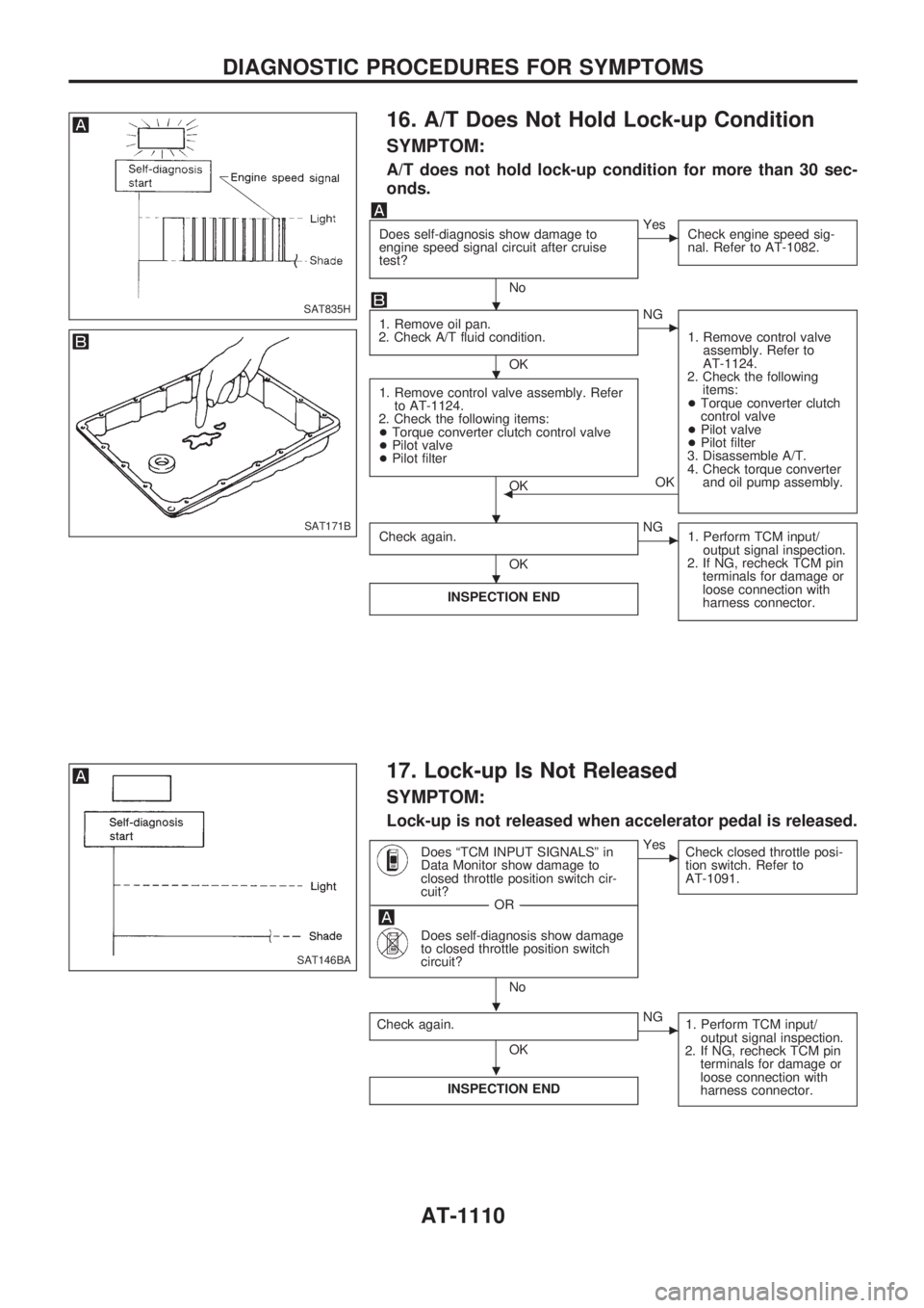
16. A/T Does Not Hold Lock-up Condition
SYMPTOM:
A/T does not hold lock-up condition for more than 30 sec-
onds.
Does self-diagnosis show damage to
engine speed signal circuit after cruise
test?
No
cYes
Check engine speed sig-
nal. Refer to AT-1082.
1. Remove oil pan.
2. Check A/T fluid condition.
OK
cNG
1. Remove control valve
assembly. Refer to
AT-1124.
2. Check the following
items:
+Torque converter clutch
control valve
+Pilot valve
+Pilot filter
3. Disassemble A/T.
4. Check torque converter
and oil pump assembly.
1. Remove control valve assembly. Refer
to AT-1124.
2. Check the following items:
+Torque converter clutch control valve
+Pilot valve
+Pilot filter
OKOKb
Check again.
OK
cNG
1. Perform TCM input/
output signal inspection.
2. If NG, recheck TCM pin
terminals for damage or
loose connection with
harness connector.
INSPECTION END
17. Lock-up Is Not Released
SYMPTOM:
Lock-up is not released when accelerator pedal is released.
Does ªTCM INPUT SIGNALSº in
Data Monitor show damage to
closed throttle position switch cir-
cuit?
------------------------------------------------------------------------------------------------------------------------------------OR------------------------------------------------------------------------------------------------------------------------------------
Does self-diagnosis show damage
to closed throttle position switch
circuit?
No
cYes
Check closed throttle posi-
tion switch. Refer to
AT-1091.
Check again.
OK
cNG
1. Perform TCM input/
output signal inspection.
2. If NG, recheck TCM pin
terminals for damage or
loose connection with
harness connector.
INSPECTION END
SAT835H
SAT171B
SAT146BA
.
.
. .
.
.
.
DIAGNOSTIC PROCEDURES FOR SYMPTOMS
AT-1110
Page 113 of 1033
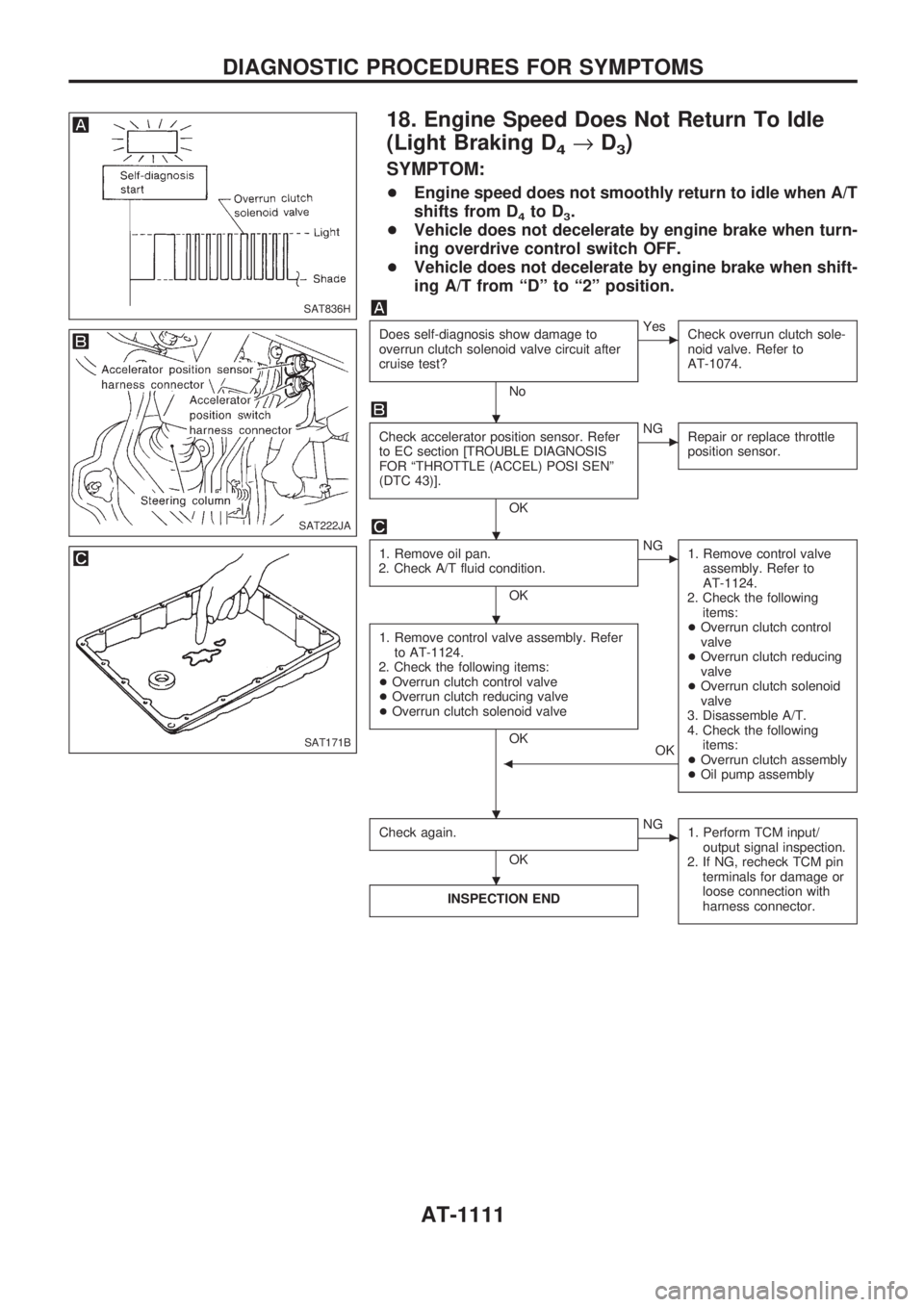
18. Engine Speed Does Not Return To Idle
(Light Braking D
4®D3)
SYMPTOM:
+Engine speed does not smoothly return to idle when A/T
shifts from D
4to D3.
+Vehicle does not decelerate by engine brake when turn-
ing overdrive control switch OFF.
+Vehicle does not decelerate by engine brake when shift-
ing A/T from ªDº to ª2º position.
Does self-diagnosis show damage to
overrun clutch solenoid valve circuit after
cruise test?
No
cYes
Check overrun clutch sole-
noid valve. Refer to
AT-1074.
Check accelerator position sensor. Refer
to EC section [TROUBLE DIAGNOSIS
FOR ªTHROTTLE (ACCEL) POSI SENº
(DTC 43)].
OK
cNG
Repair or replace throttle
position sensor.
1. Remove oil pan.
2. Check A/T fluid condition.
OK
cNG
1. Remove control valve
assembly. Refer to
AT-1124.
2. Check the following
items:
+Overrun clutch control
valve
+Overrun clutch reducing
valve
+Overrun clutch solenoid
valve
3. Disassemble A/T.
4. Check the following
items:
+Overrun clutch assembly
+Oil pump assembly
1. Remove control valve assembly. Refer
to AT-1124.
2. Check the following items:
+Overrun clutch control valve
+Overrun clutch reducing valve
+Overrun clutch solenoid valve
OK
OK
b
Check again.
OK
cNG
1. Perform TCM input/
output signal inspection.
2. If NG, recheck TCM pin
terminals for damage or
loose connection with
harness connector.
INSPECTION END
SAT836H
SAT222JA
SAT171B
.
.
.
. .
.
DIAGNOSTIC PROCEDURES FOR SYMPTOMS
AT-1111
Page 127 of 1033
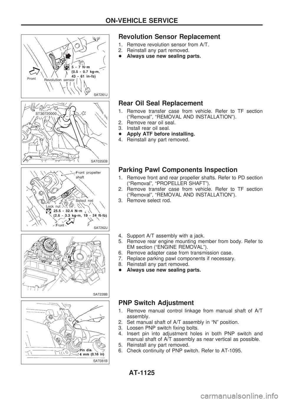
Revolution Sensor Replacement
1. Remove revolution sensor from A/T.
2. Reinstall any part removed.
+Always use new sealing parts.
Rear Oil Seal Replacement
1. Remove transfer case from vehicle. Refer to TF section
(ªRemovalº, ªREMOVAL AND INSTALLATIONº).
2. Remove rear oil seal.
3. Install rear oil seal.
+Apply ATF before installing.
4. Reinstall any part removed.
Parking Pawl Components Inspection
1. Remove front and rear propeller shafts. Refer to PD section
(ªRemovalº, ªPROPELLER SHAFTº).
2. Remove transfer case from vehicle. Refer to TF section
(ªRemovalº, ªREMOVAL AND INSTALLATIONº).
3. Remove select rod.
4. Support A/T assembly with a jack.
5. Remove rear engine mounting member from body. Refer to
EM section (ªENGINE REMOVALº).
6. Remove adapter case from transmission case.
7. Replace parking pawl components if necessary.
8. Reinstall any part removed.
+Always use new sealing parts.
PNP Switch Adjustment
1. Remove manual control linkage from manual shaft of A/T
assembly.
2. Set manual shaft of A/T assembly in ªNº position.
3. Loosen PNP switch fixing bolts.
4. Insert pin into adjustment holes in both PNP switch and
manual shaft of A/T assembly as near vertical as possible.
5. Reinstall any part removed.
6. Check continuity of PNP switch. Refer to AT-1095.
SAT261J
SAT035EB
SAT262J
SAT228B
SAT081B
ON-VEHICLE SERVICE
AT-1125