Page 758 of 1033
Removal and Installation
REMOVAL
1. Remove the following parts.
+Engine cover
+Intercooler
+Air inlet pipe
+Throttle body
+Wires, harnesses, tubes and pipes
2. Loosen holding bolts in the reverse order of that shown in the
figure and remove.
3. Remove rocker cover to the direction of glow plug tilt.
4. Remove glow plug oil seals.
SEM315G
SEM316G
ROCKER COVERZD
EM-1020
Page 759 of 1033
INSTALLATION
1. Temporarily tighten holding bolts in the numerical order
shown in the figure.
2. Apply Three Bond 1207C (KP510 00150) to the area shown
in the figure.
3. Use a scraper to remove old liquid gasket.
4. Apply once more.
5. Apply engine oil to glow plug oil seals and install them.
6. Tighten holding bolts in the numerical order shown in the
figure.
7. Re-tighten to the same torque in the same order as above.
8. Install in the reverse order of removal.
SEM317G
FEM001
SEM316G
ROCKER COVERZD
Removal and Installation (Cont'd)
EM-1021
Page 760 of 1033
Removal and Installation
REMOVAL [OIL PAN (LOWER)]
1. Remove the following parts.
+Remove undercover.
+Extract the engine oil.
2. Loosen the installation bolts in the reverse order of that
shown in the figure and then remove.
3. Using a seal cutter (SST), cut the liquid gasket to separate
it.
SEM319G
SEM341G
OIL PAN & OIL STRAINERZD
EM-1022
Page 761 of 1033
![NISSAN PATROL 2000 Electronic Repair Manual INSTALLATION [OIL PAN (LOWER)]
1. Install oil pan (Lower).
a. Use a scraper to remove all traces of liquid gasket from
mating surfaces.
+Also remove traces of liquid gasket from mating surface of oil
NISSAN PATROL 2000 Electronic Repair Manual INSTALLATION [OIL PAN (LOWER)]
1. Install oil pan (Lower).
a. Use a scraper to remove all traces of liquid gasket from
mating surfaces.
+Also remove traces of liquid gasket from mating surface of oil](/manual-img/5/57367/w960_57367-760.png)
INSTALLATION [OIL PAN (LOWER)]
1. Install oil pan (Lower).
a. Use a scraper to remove all traces of liquid gasket from
mating surfaces.
+Also remove traces of liquid gasket from mating surface of oil
pan (Upper).
+Remove old liquid gasket from the bolt hole and thread.
b. Apply a continuous bead of liquid gasket to mating surface
of oil pan (Lower).
+Use Genuine Liquid Gasket or equivalent.
+Apply liquid gasket to the groove on the mating surface.
+Allow 7 mm (0.28 in) clearance around bolt holes.
c. Apply liquid gasket to inner sealing surface as shown in fig-
ure.
+Be sure liquid gasket is 3.5 to 4.5 mm (0.138 to 0.177 in).
+Attaching should be done within 5 minutes after coating.
2. Tighten the installation bolts in the order shown in the figure.
3. Install in the reverse order of removal.
REMOVAL [OIL PAN (UPPER) AND OIL STRAINER]
1. Remove the following parts.
+Engine cover
+Under covers
+Stabilizer; Refer to FA section in original Service Manual.
+Exhaust front tube and its bracket; Refer to FE section in
original Service Manual.
+Front propeller shaft and rear propeller shaft; Refer to PD
section in original Service Manual.
+Starter motor; Refer to EL section in original Service Manual.
+A/T or M/T assembly with transfer; Refer to AT section or MT
section in original Service Manual.
NOTE:
As there is a converter/clutch housing side oil pan (upper)
installation bolt as well, the transmission will also need to
be removed.
2. Loosen the installation bolts in the reverse order of that
shown in the figure and then remove.
3.
Using a seal cutter (SST), cut the liquid gasket to separate it.
4. Remove oil strainer
INSTALLATION [OIL PAN (UPPER) AND OIL STRAINER]
1. Clean oil strainer if any object is attached, and install oil
strainer.
2. Install oil pan (Upper).
a. Use a scraper to remove all traces of liquid gasket from
mating surfaces.
+Also remove traces of liquid gasket from mating surface of
cylinder block, front cover and oil pan (Lower).
+Remove old liquid gasket from the bolt hole and thread.
b. Apply a continuous bead of liquid gasket to mating surface
of oil pan (Upper).
SEM159F
SEM345GA
SEM346G
SEM159F
SEM347GA
OIL PAN & OIL STRAINERZD
Removal and Installation (Cont'd)
EM-1023
Page 767 of 1033

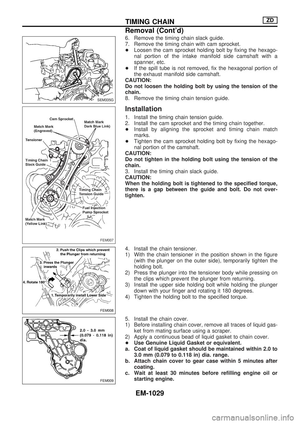
6. Remove the timing chain slack guide.
7. Remove the timing chain with cam sprocket.
+Loosen the cam sprocket holding bolt by fixing the hexago-
nal portion of the intake manifold side camshaft with a
spanner, etc.
+If the spill tube is not removed, fix the hexagonal portion of
the exhaust manifold side camshaft.
CAUTION:
Do not loosen the holding bolt by using the tension of the
chain.
8. Remove the timing chain tension guide.
Installation
1. Install the timing chain tension guide.
2. Install the cam sprocket and the timing chain together.
+Install by aligning the sprocket and timing chain match
marks.
+Tighten the cam sprocket holding bolt by fixing the hexago-
nal portion of the camshaft.
CAUTION:
Do not tighten in the holding bolt using the tension of the
chain.
3. Install the timing chain slack guide.
CAUTION:
When the holding bolt is tightened to the specified torque,
there is a gap between the guide and bolt. Do not over-
tighten.
4. Install the chain tensioner.
1) With the chain tensioner in the position shown in the figure
(with the plunger on the outer side), temporarily tighten the
holding bolt.
2) Press the plunger into the tensioner body while pressing on
the clips which prevent the plunger from returning.
3) Install the upper side holding bolt while holding the plunger
down with your finger and rotating it 180 degrees.
4) Tighten the holding bolt to the specified torque.
5. Install the chain cover.
1) Before installing chain cover, remove all traces of liquid gas-
ket from mating surface using a scraper.
2) Apply a continuous bead of liquid gasket to chain cover.
+Use Genuine Liquid Gasket or equivalent.
a. Coat of liquid gasket should be maintained within 2.0 to
3.0 mm (0.079 to 0.118 in) dia. range.
b. Attach chain cover to gear case within 5 minutes after
coating.
c. Wait at least 30 minutes before refilling engine oil or
starting engine.
SEM335G
FEM007
FEM008
FEM009
TIMING CHAINZD
Removal (Cont'd)
EM-1029
Page 770 of 1033

3. Remove injection tube and injection nozzle assembly. Refer
to EC section, ªInjection Tube and Injection Nozzleº in
ªBASIC SERVICE PROCEDUREº.
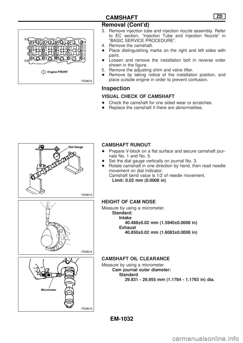
4. Remove the camshaft.
+Place distinguishing marks on the right and left sides with
paint.
+Loosen and remove the installation bolt in reverse order
shown in the figure.
5. Remove the adjusting shim and valve lifter.
+Remove by taking notice of the installation position, and
place outside engine in order to prevent confusion.
Inspection
VISUAL CHECK OF CAMSHAFT
+Check the camshaft for one sided wear or scratches.
+Replace the camshaft if there are abnormalities.
CAMSHAFT RUNOUT
+Prepare V-block on a flat surface and secure camshaft jour-
nals No. 1 and No. 5.
+Set the dial gauge vertically on journal No. 3.
+Rotate camshaft in one direction by hand, then read needle
movement on dial indicator.
Camshaft bend value is 1/2 of needle movement.
Limit: 0.02 mm (0.0008 in)
HEIGHT OF CAM NOSE
Measure by using a micrometer.
Standard:
Intake
40.488 0.02 mm (1.5940 0.0008 in)
Exhaust
40.850 0.02 mm (1.6083 0.0008 in)
CAMSHAFT OIL CLEARANCE
Measure by using a micrometer.
Cam journal outer diameter:
Standard
29.931 - 29.955 mm (1.1784 - 1.1793 in) dia.
FEM012
FEM013
FEM014
FEM015
CAMSHAFTZD
Removal (Cont'd)
EM-1032
Page 775 of 1033

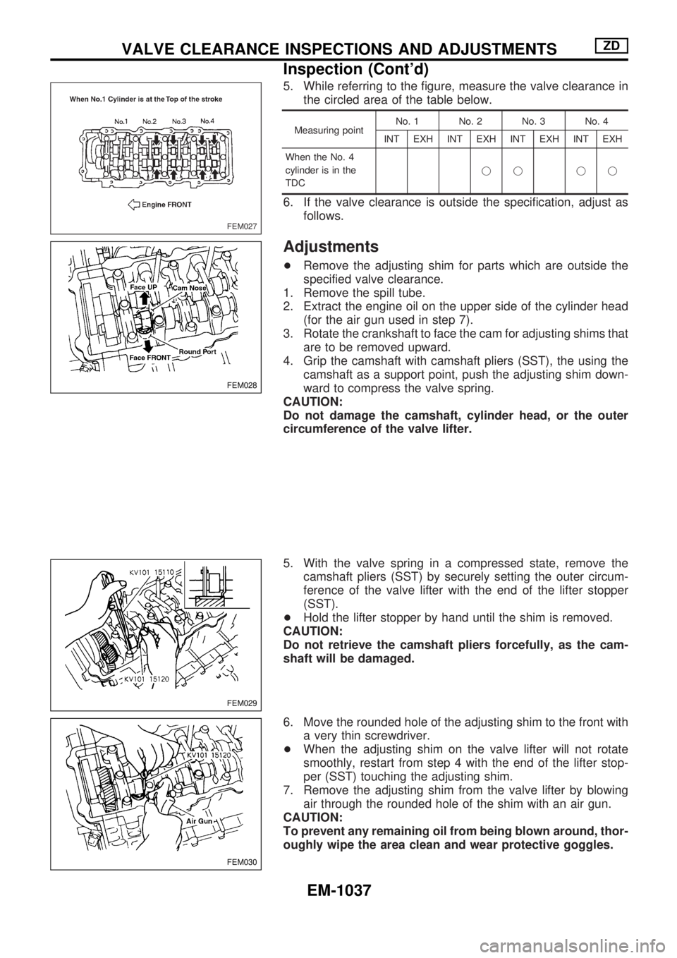
5. While referring to the figure, measure the valve clearance in
the circled area of the table below.
Measuring pointNo. 1 No. 2 No. 3 No. 4
INT EXH INT EXH INT EXH INT EXH
When the No. 4
cylinder is in the
TDCjj jj
6. If the valve clearance is outside the specification, adjust as
follows.
Adjustments
+Remove the adjusting shim for parts which are outside the
specified valve clearance.
1. Remove the spill tube.
2. Extract the engine oil on the upper side of the cylinder head
(for the air gun used in step 7).
3. Rotate the crankshaft to face the cam for adjusting shims that
are to be removed upward.
4. Grip the camshaft with camshaft pliers (SST), the using the
camshaft as a support point, push the adjusting shim down-
ward to compress the valve spring.
CAUTION:
Do not damage the camshaft, cylinder head, or the outer
circumference of the valve lifter.
5. With the valve spring in a compressed state, remove the
camshaft pliers (SST) by securely setting the outer circum-
ference of the valve lifter with the end of the lifter stopper
(SST).
+Hold the lifter stopper by hand until the shim is removed.
CAUTION:
Do not retrieve the camshaft pliers forcefully, as the cam-
shaft will be damaged.
6. Move the rounded hole of the adjusting shim to the front with
a very thin screwdriver.
+When the adjusting shim on the valve lifter will not rotate
smoothly, restart from step 4 with the end of the lifter stop-
per (SST) touching the adjusting shim.
7. Remove the adjusting shim from the valve lifter by blowing
air through the rounded hole of the shim with an air gun.
CAUTION:
To prevent any remaining oil from being blown around, thor-
oughly wipe the area clean and wear protective goggles.
FEM027
FEM028
FEM029
FEM030
VALVE CLEARANCE INSPECTIONS AND ADJUSTMENTSZD
Inspection (Cont'd)
EM-1037
Page 778 of 1033

Removal
1. Remove the following parts.
+Undercover
+Engine oil (Drain)
+Engine coolant (Drain)
+Engine cover
+Intercooler
+Air inlet pipe
+Air cleaner case
+Throttle body
+Swirl and intake air control valve control solenoid valve and
bracket
+Vacuum tank
+Glow plate
+Rocker cover
+Spill tube
+Radiator shrouds (Rear and Lower)
+Cooling fan
+Radiator hose (Upper and Lower)
+Auxiliary belt and auto tensioner.
2. Remove the alternator.
3. Remove the A/C compressor and bracket with piping con-
nected. Move and support it at the LH side of engine bay with
a rope to avoid putting load on piping.
Refer to HA section in Nissan Service Manual (Supplement
I: Publication No. SM0E-Y61AE0E.)
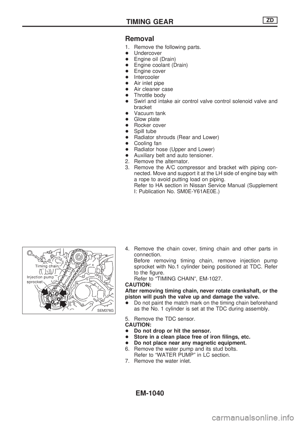
4. Remove the chain cover, timing chain and other parts in
connection.
Before removing timing chain, remove injection pump
sprocket with No.1 cylinder being positioned at TDC. Refer
to the figure.
Refer to ªTIMING CHAINº, EM-1027.
CAUTION:
After removing timing chain, never rotate crankshaft, or the
piston will push the valve up and damage the valve.
+Do not paint the match mark on the timing chain beforehand
as the No. 1 cylinder is set at the TDC during assembly.
5. Remove the TDC sensor.
CAUTION:
+Do not drop or hit the sensor.
+Store in a clean place free of iron filings, etc.
+Do not place near any magnetic equipment.
6. Remove the water pump and its stud bolts.
Refer to ªWATER PUMPº in LC section.
7. Remove the water inlet.
SEM376G
TIMING GEARZD
EM-1040