Page 912 of 1033

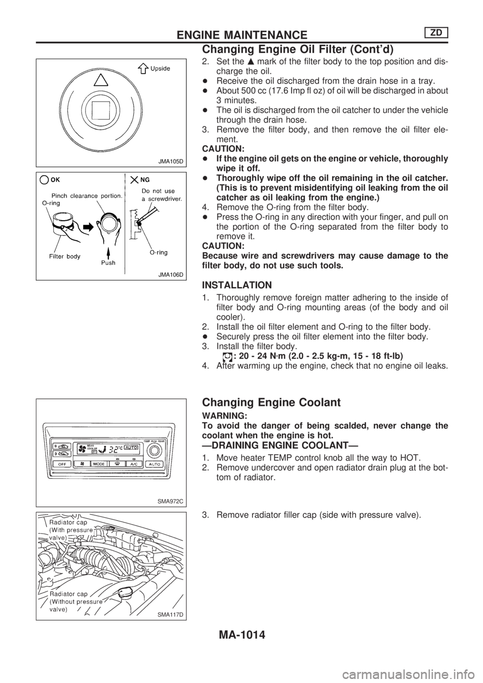
2. Set themmark of the filter body to the top position and dis-
charge the oil.
+Receive the oil discharged from the drain hose in a tray.
+About 500 cc (17.6 Imp fl oz) of oil will be discharged in about
3 minutes.
+The oil is discharged from the oil catcher to under the vehicle
through the drain hose.
3. Remove the filter body, and then remove the oil filter ele-
ment.
CAUTION:
+If the engine oil gets on the engine or vehicle, thoroughly
wipe it off.
+Thoroughly wipe off the oil remaining in the oil catcher.
(This is to prevent misidentifying oil leaking from the oil
catcher as oil leaking from the engine.)
4. Remove the O-ring from the filter body.
+Press the O-ring in any direction with your finger, and pull on
the portion of the O-ring separated from the filter body to
remove it.
CAUTION:
Because wire and screwdrivers may cause damage to the
filter body, do not use such tools.
INSTALLATION
1. Thoroughly remove foreign matter adhering to the inside of
filter body and O-ring mounting areas (of the body and oil
cooler).
2. Install the oil filter element and O-ring to the filter body.
+Securely press the oil filter element into the filter body.
3. Install the filter body.
:20-24Nzm (2.0 - 2.5 kg-m, 15 - 18 ft-lb)
4. After warming up the engine, check that no engine oil leaks.
Changing Engine Coolant
WARNING:
To avoid the danger of being scalded, never change the
coolant when the engine is hot.
ÐDRAINING ENGINE COOLANTÐ
1. Move heater TEMP control knob all the way to HOT.
2. Remove undercover and open radiator drain plug at the bot-
tom of radiator.
3. Remove radiator filler cap (side with pressure valve).
JMA105D
JMA106D
SMA972C
SMA117D
ENGINE MAINTENANCEZD
Changing Engine Oil Filter (Cont'd)
MA-1014
Page 920 of 1033
Engine Maintenance (ZD)
INSPECTION AND ADJUSTMENT
Oil capacity (Refill capacity)
Unit:!(Imp qt)
With oil filter change 5.7 (5)
Without oil filter change 5.2 (4-5/8)
Cooling system check
Unit: kPa (bar, kg/cm2, psi)
Cooling system testing pressure 98 (0.98, 1.0, 14)
Radiator cap relief pressure59-98
(0.59 - 0.98, 0.6 - 1.0,9-14)
SERVICE DATA AND SPECIFICATIONS (SDS)
MA-1022
Page 927 of 1033
Removal
1. Remove front and rear propeller shafts. Refer to PD section
(``Removal and Installation'', ``PROPELLER SHAFT'').
2. Remove clutch operating cylinder.
3. Remove exhaust front and rear tubes. Refer to FE section
(``EXHAUST SYSTEM'').
4. Disconnect vehicle speed sensor, back-up lamp switch, 4WD
switch and neutral position switch harness connector.
5. Remove center brake cable. Refer to BR section.
6. Remove shift lever of transmission. Refer to MT-1014
(FS5R50B).
7. Remove transfer control lever. Refer to TF section
(``Removal'', ``REMOVAL AND INSTALLATION'').
8. Support engine by placing a jack under oil pan.
lDo not place jack under the oil pan drain plug.
9. Remove transmission with transfer from engine.
WARNING:
Support Manual Transmission with transfer, while removing
it.
SMT321D Exhaust front tube
Front
Exhaust rear tube
Clutch operating cylinder
Rear propeller tube
Front propeller tube
REMOVAL AND INSTALLATIONFS5R50B
MT-1007
Page 928 of 1033
Installation
lApply sealant as below:
lTighten bolts securing transmission.
Engine BoltsTightening torque
N´m (kg-m, ft-lb)!mm (in)
ZD30DDTi
V1M/T to engine block83 - 113
(8.5 - 11.5, 61 - 83)100 (3.94)
V2M/T to engine oil pan29-39
(3.0 - 4.0, 22 - 29)100 (3.94)
V3Engine oil pan to M/T29-39
(3.0 - 4.0, 22 - 29)70 (2.76)
SMT280D Engine rear plate
Transmission case
Engine block
23.6 (0.929)
23.6 (0.929)
Do not apply sealant
in this range.1) Place
2) Sealant
: Sticked out portion for engine rear plate
from transmission case.
: Mating surface of transmission case and
rear plate.
: Apply genuine anaerobic liquid gasket,
Three Bond TB1207B or TB1207D.
: Apply genuine anaerobic liquid gasket,
Three Bond TB1215 or TB1207D.
Transmission case
Grommet
Engine rear plate Starter Sealant
Rear plate
Unit: mm (in)
SMT324DB ZD30DDTi engine
For starterDowel hole
Dowel hole
(Not used) M/T to engine
Engine to M/T
REMOVAL AND INSTALLATIONFS5R50B
MT-1008
Page 931 of 1033

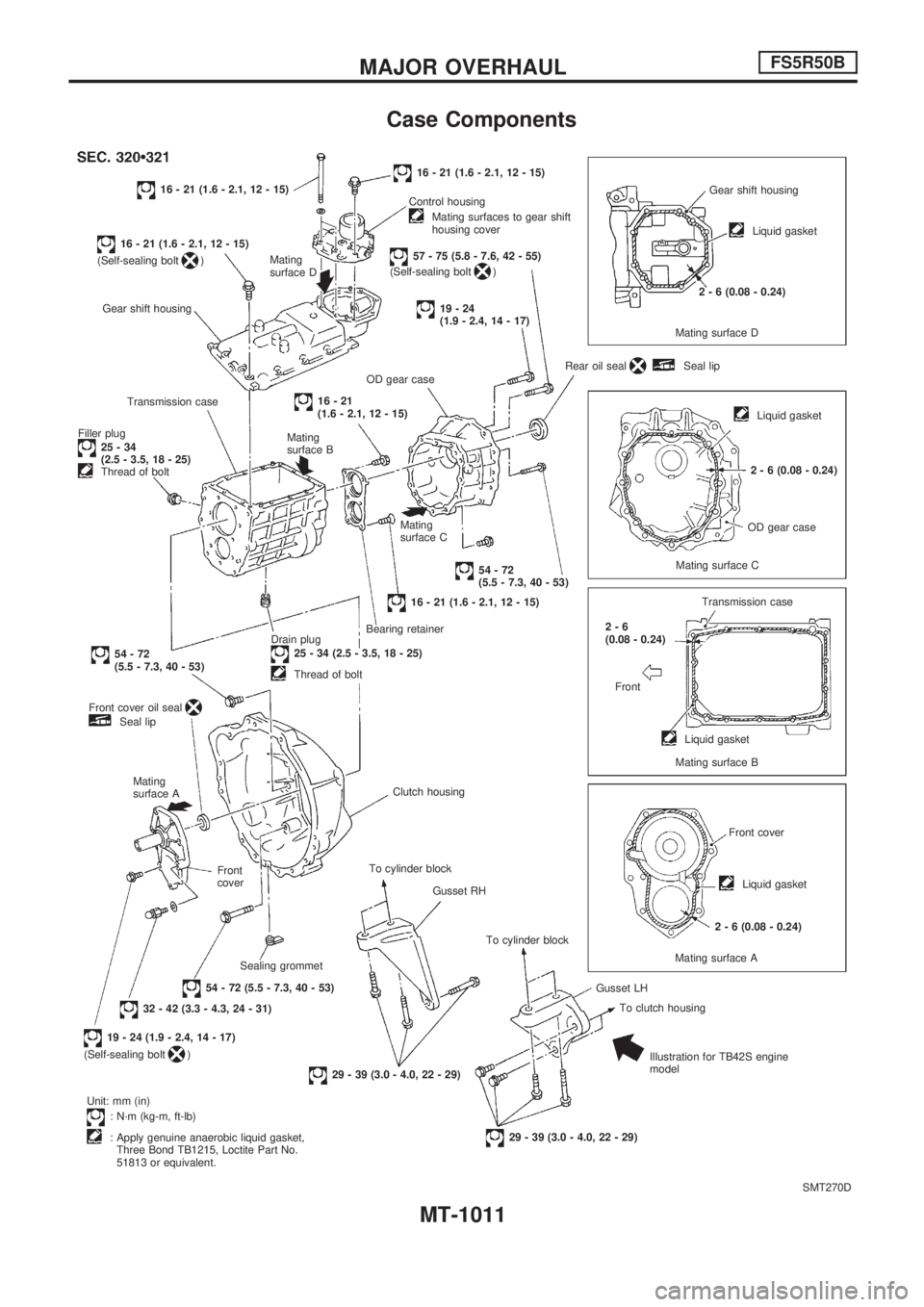
Case Components
SMT270D
16 - 21 (1.6 - 2.1, 12 - 15)
16 - 21 (1.6 - 2.1, 12 - 15)
(Self-sealing bolt
)Mating
surface D
Gear shift housing
Transmission case
Filler plug
25-34
(2.5 - 3.5, 18 - 25)
Thread of bolt
54-72
(5.5 - 7.3, 40 - 53)
Front cover oil seal
Seal lip
Mating
surface A
Front
cover
Sealing grommet
54 - 72 (5.5 - 7.3, 40 - 53)
32 - 42 (3.3 - 4.3, 24 - 31)
19 - 24 (1.9 - 2.4, 14 - 17)
(Self-sealing bolt
)
Unit: mm (in)
: N´m (kg-m, ft-lb)
: Apply genuine anaerobic liquid gasket,
Three Bond TB1215, Loctite Part No.
51813 or equivalent.
29 - 39 (3.0 - 4.0, 22 - 29)
29 - 39 (3.0 - 4.0, 22 - 29)Illustration for TB42S engine
model To clutch housing Gusset LH To cylinder block Gusset RH To cylinder blockClutch housing Drain plug
25 - 34 (2.5 - 3.5, 18 - 25)
Thread of boltBearing retainer
16 - 21 (1.6 - 2.1, 12 - 15)
54-72
(5.5 - 7.3, 40 - 53) Mating
surface C Mating
surface B
16-21
(1.6 - 2.1, 12 - 15)OD gear caseRear oil seal
Seal lip
19-24
(1.9 - 2.4, 14 - 17)
57 - 75 (5.8 - 7.6, 42 - 55)
(Self-sealing bolt) Control housing
Mating surfaces to gear shift
housing cover
16 - 21 (1.6 - 2.1, 12 - 15)
Gear shift housing
Liquid gasket
2 - 6 (0.08 - 0.24)
Mating surface D
Liquid gasket
2 - 6 (0.08 - 0.24)
OD gear case
Mating surface C
Transmission case
2-6
(0.08 - 0.24)
Front
Liquid gasket
Mating surface B
Front cover
Liquid gasket
2 - 6 (0.08 - 0.24)
Mating surface A
MAJOR OVERHAULFS5R50B
MT-1011
Page 1028 of 1033
STEERING SYSTEM
SECTION
ST
MODIFICATION NOTICE:
+Power steering oil pump for ZD30ETi engine has been adopted.
CONTENTS
POWER STEERING OIL PUMP.......................... 1002
Removal and Installation ................................. 1002
Disassembly and Assembly ............................. 1003SERVICE DATA AND SPECIFICATIONS
(SDS).................................................................... 1004
Inspection and Adjustment .............................. 1004
ST