2000 NISSAN PATROL check engine light
[x] Cancel search: check engine lightPage 267 of 1033
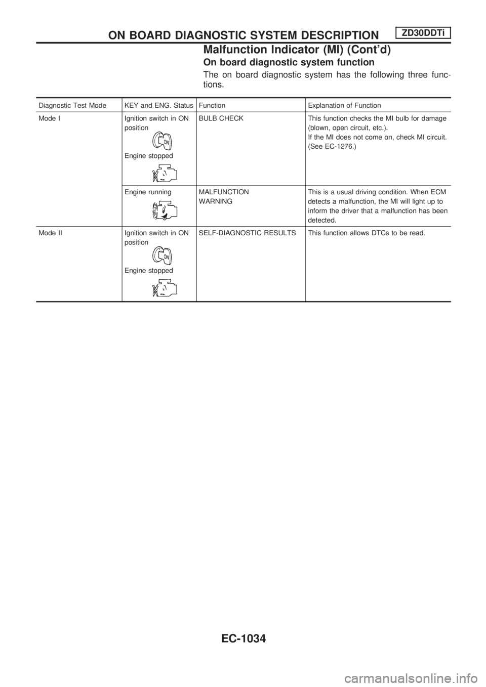
On board diagnostic system function
The on board diagnostic system has the following three func-
tions.
Diagnostic Test Mode KEY and ENG. Status Function Explanation of Function
Mode I Ignition switch in ON
position
Engine stopped
BULB CHECK This function checks the MI bulb for damage
(blown, open circuit, etc.).
If the MI does not come on, check MI circuit.
(See EC-1276.)
Engine running
MALFUNCTION
WARNINGThis is a usual driving condition. When ECM
detects a malfunction, the MI will light up to
inform the driver that a malfunction has been
detected.
Mode II Ignition switch in ON
position
Engine stopped
SELF-DIAGNOSTIC RESULTS This function allows DTCs to be read.
ON BOARD DIAGNOSTIC SYSTEM DESCRIPTIONZD30DDTi
Malfunction Indicator (MI) (Cont'd)
EC-1034
Page 333 of 1033
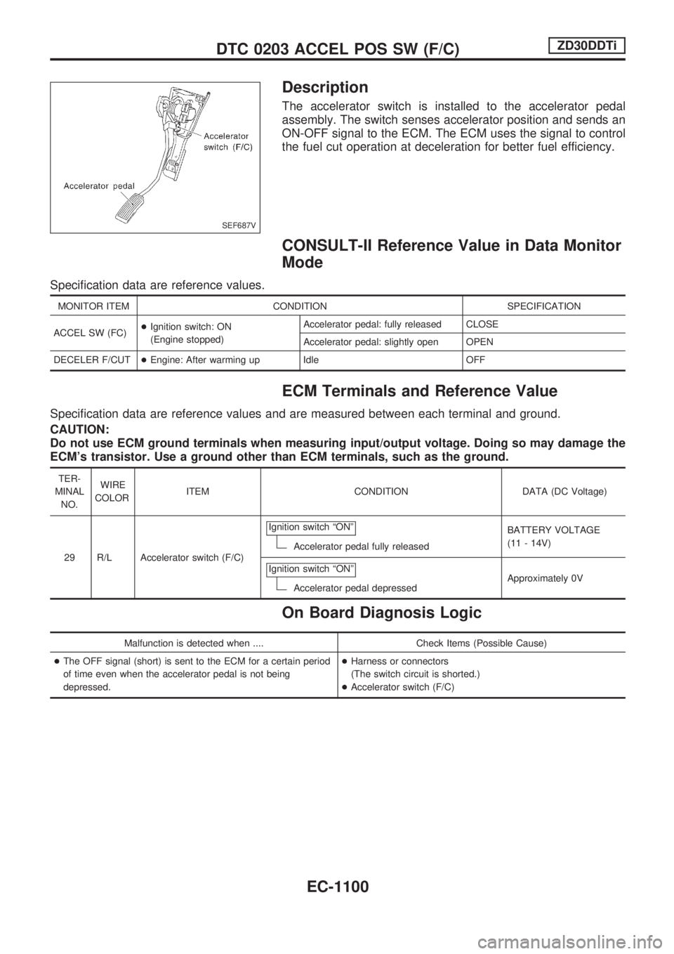
Description
The accelerator switch is installed to the accelerator pedal
assembly. The switch senses accelerator position and sends an
ON-OFF signal to the ECM. The ECM uses the signal to control
the fuel cut operation at deceleration for better fuel efficiency.
CONSULT-II Reference Value in Data Monitor
Mode
Specification data are reference values.
MONITOR ITEM CONDITION SPECIFICATION
ACCEL SW (FC)+Ignition switch: ON
(Engine stopped)Accelerator pedal: fully released CLOSE
Accelerator pedal: slightly open OPEN
DECELER F/CUT+Engine: After warming up Idle OFF
ECM Terminals and Reference Value
Specification data are reference values and are measured between each terminal and ground.
CAUTION:
Do not use ECM ground terminals when measuring input/output voltage. Doing so may damage the
ECM's transistor. Use a ground other than ECM terminals, such as the ground.
TER-
MINAL
NO.WIRE
COLORITEM CONDITION DATA (DC Voltage)
29 R/L Accelerator switch (F/C)Ignition switch ªONº
Accelerator pedal fully releasedBATTERY VOLTAGE
(11 - 14V)
Ignition switch ªONº
Accelerator pedal depressedApproximately 0V
On Board Diagnosis Logic
Malfunction is detected when .... Check Items (Possible Cause)
+The OFF signal (short) is sent to the ECM for a certain period
of time even when the accelerator pedal is not being
depressed.+Harness or connectors
(The switch circuit is shorted.)
+Accelerator switch (F/C)
SEF687V
DTC 0203 ACCEL POS SW (F/C)ZD30DDTi
EC-1100
Page 511 of 1033
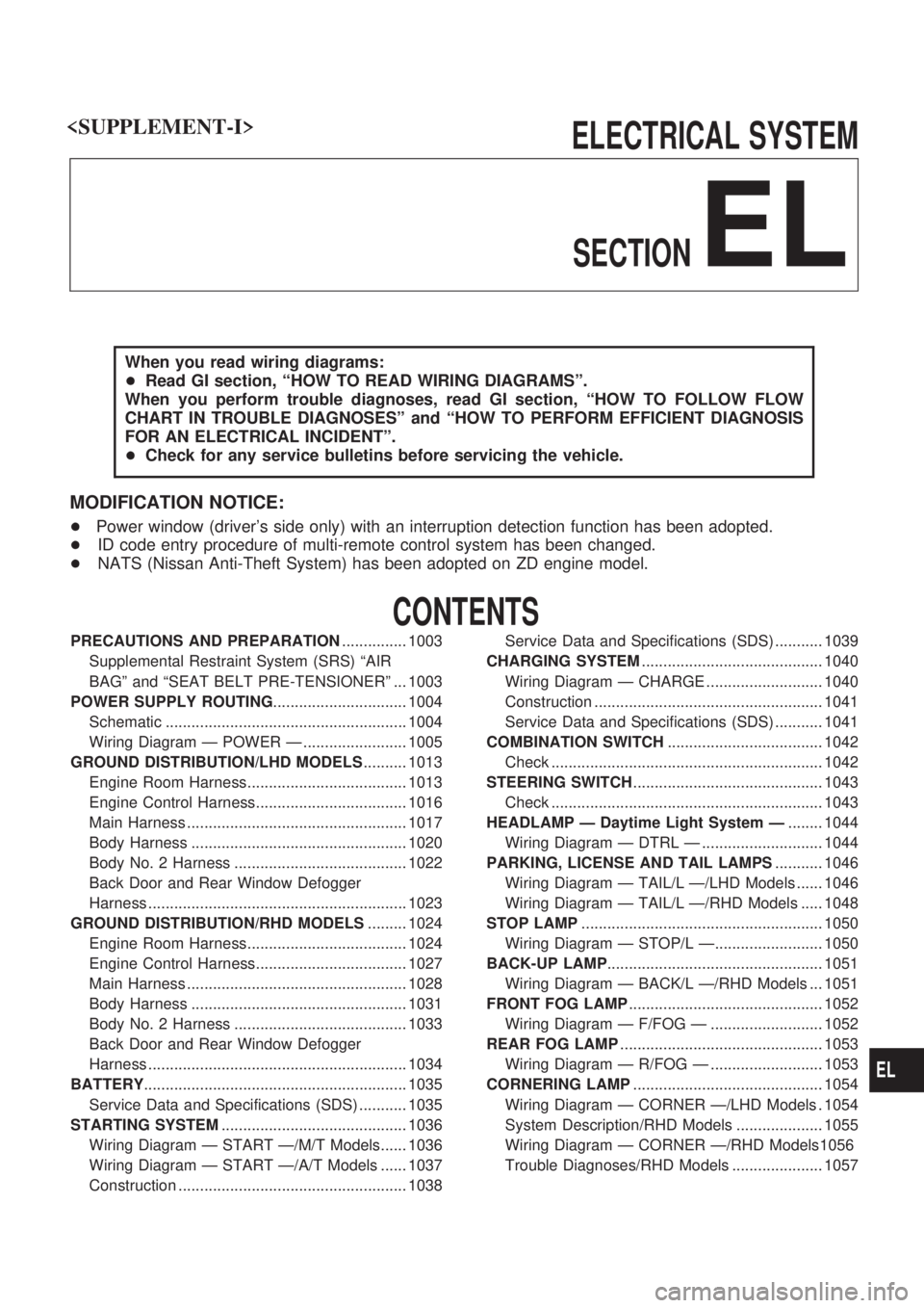
ELECTRICAL SYSTEM
SECTION
EL
When you read wiring diagrams:
+Read GI section, ªHOW TO READ WIRING DIAGRAMSº.
When you perform trouble diagnoses, read GI section, ªHOW TO FOLLOW FLOW
CHART IN TROUBLE DIAGNOSESº and ªHOW TO PERFORM EFFICIENT DIAGNOSIS
FOR AN ELECTRICAL INCIDENTº.
+Check for any service bulletins before servicing the vehicle.
MODIFICATION NOTICE:
+Power window (driver's side only) with an interruption detection function has been adopted.
+ID code entry procedure of multi-remote control system has been changed.
+NATS (Nissan Anti-Theft System) has been adopted on ZD engine model.
CONTENTS
PRECAUTIONS AND PREPARATION............... 1003
Supplemental Restraint System (SRS) ªAIR
BAGº and ªSEAT BELT PRE-TENSIONERº ... 1003
POWER SUPPLY ROUTING............................... 1004
Schematic ........................................................ 1004
Wiring Diagram Ð POWER Ð ........................ 1005
GROUND DISTRIBUTION/LHD MODELS.......... 1013
Engine Room Harness..................................... 1013
Engine Control Harness................................... 1016
Main Harness ................................................... 1017
Body Harness .................................................. 1020
Body No. 2 Harness ........................................ 1022
Back Door and Rear Window Defogger
Harness ............................................................ 1023
GROUND DISTRIBUTION/RHD MODELS......... 1024
Engine Room Harness..................................... 1024
Engine Control Harness................................... 1027
Main Harness ................................................... 1028
Body Harness .................................................. 1031
Body No. 2 Harness ........................................ 1033
Back Door and Rear Window Defogger
Harness ............................................................ 1034
BATTERY............................................................. 1035
Service Data and Specifications (SDS) ........... 1035
STARTING SYSTEM........................................... 1036
Wiring Diagram Ð START Ð/M/T Models...... 1036
Wiring Diagram Ð START Ð/A/T Models ...... 1037
Construction ..................................................... 1038Service Data and Specifications (SDS) ........... 1039
CHARGING SYSTEM.......................................... 1040
Wiring Diagram Ð CHARGE ........................... 1040
Construction ..................................................... 1041
Service Data and Specifications (SDS) ........... 1041
COMBINATION SWITCH.................................... 1042
Check ............................................................... 1042
STEERING SWITCH............................................ 1043
Check ............................................................... 1043
HEADLAMP Ð Daytime Light System Ð........ 1044
Wiring Diagram Ð DTRL Ð ............................ 1044
PARKING, LICENSE AND TAIL LAMPS........... 1046
Wiring Diagram Ð TAIL/L Ð/LHD Models ...... 1046
Wiring Diagram Ð TAIL/L Ð/RHD Models ..... 1048
STOP LAMP........................................................ 1050
Wiring Diagram Ð STOP/L Ð......................... 1050
BACK-UP LAMP.................................................. 1051
Wiring Diagram Ð BACK/L Ð/RHD Models ... 1051
FRONT FOG LAMP............................................. 1052
Wiring Diagram Ð F/FOG Ð .......................... 1052
REAR FOG LAMP............................................... 1053
Wiring Diagram Ð R/FOG Ð .......................... 1053
CORNERING LAMP............................................ 1054
Wiring Diagram Ð CORNER Ð/LHD Models . 1054
System Description/RHD Models .................... 1055
Wiring Diagram Ð CORNER Ð/RHD Models1056
Trouble Diagnoses/RHD Models ..................... 1057
EL
Page 682 of 1033
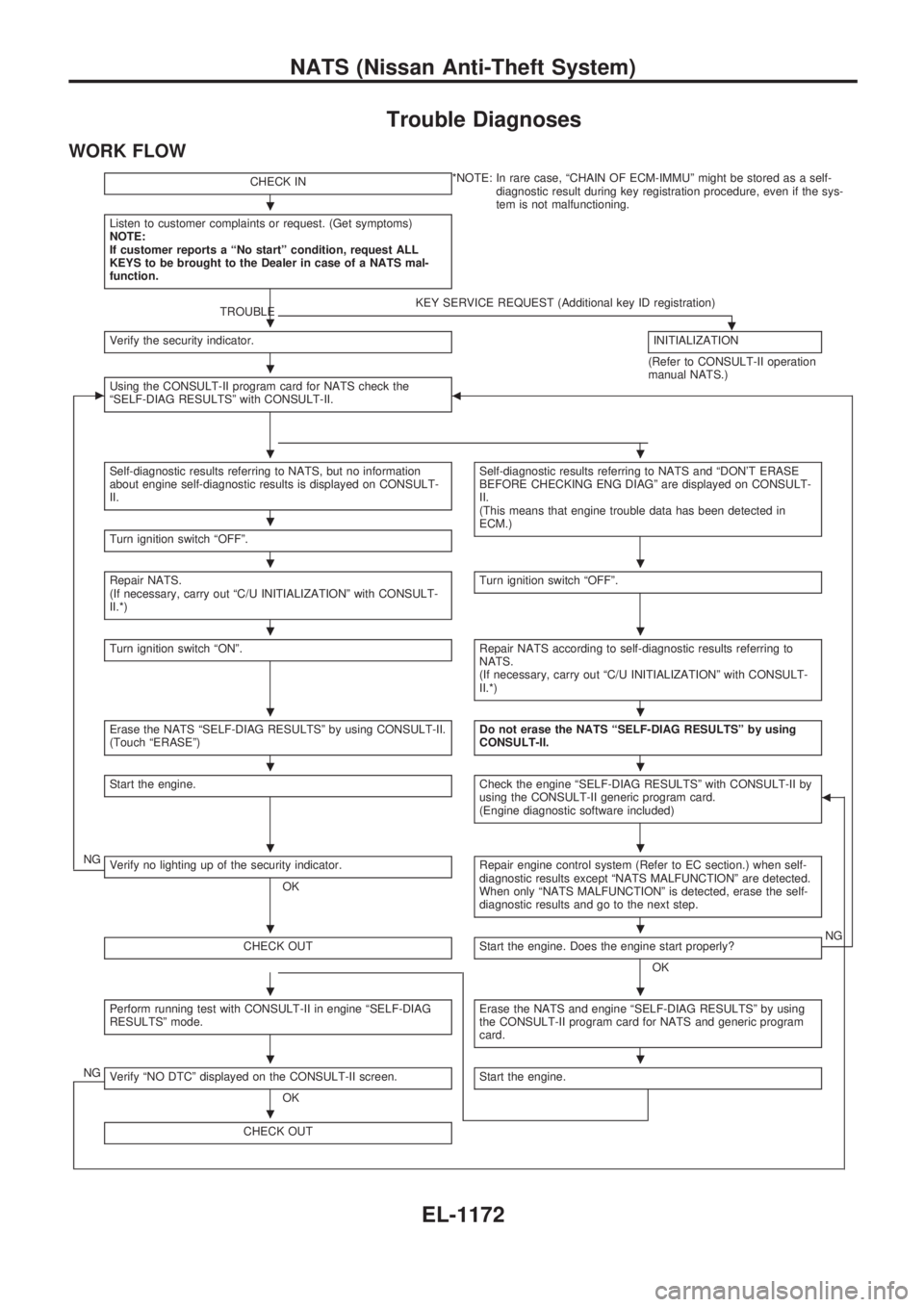
Trouble Diagnoses
WORK FLOW
CHECK IN*NOTE: In rare case, ªCHAIN OF ECM-IMMUº might be stored as a self-
diagnostic result during key registration procedure, even if the sys-
tem is not malfunctioning.
Listen to customer complaints or request. (Get symptoms)
NOTE:
If customer reports a ªNo startº condition, request ALL
KEYS to be brought to the Dealer in case of a NATS mal-
function.
TROUBLEKEY SERVICE REQUEST (Additional key ID registration).Verify the security indicator.INITIALIZATION
(Refer to CONSULT-II operation
manual NATS.)
cUsing the CONSULT-II program card for NATS check the
ªSELF-DIAG RESULTSº with CONSULT-II.b
Self-diagnostic results referring to NATS, but no information
about engine self-diagnostic results is displayed on CONSULT-
II.Self-diagnostic results referring to NATS and ªDON'T ERASE
BEFORE CHECKING ENG DIAGº are displayed on CONSULT-
II.
(This means that engine trouble data has been detected in
ECM.)
Turn ignition switch ªOFFº.
Repair NATS.
(If necessary, carry out ªC/U INITIALIZATIONº with CONSULT-
II.*)Turn ignition switch ªOFFº.
Turn ignition switch ªONº.Repair NATS according to self-diagnostic results referring to
NATS.
(If necessary, carry out ªC/U INITIALIZATIONº with CONSULT-
II.*)
Erase the NATS ªSELF-DIAG RESULTSº by using CONSULT-II.
(Touch ªERASEº)Do not erase the NATS ªSELF-DIAG RESULTSº by using
CONSULT-II.
Start the engine.Check the engine ªSELF-DIAG RESULTSº with CONSULT-II by
using the CONSULT-II generic program card.
(Engine diagnostic software included)b
NGVerify no lighting up of the security indicator.
OKRepair engine control system (Refer to EC section.) when self-
diagnostic results except ªNATS MALFUNCTIONº are detected.
When only ªNATS MALFUNCTIONº is detected, erase the self-
diagnostic results and go to the next step.
CHECK OUTStart the engine. Does the engine start properly?
OKNG
Perform running test with CONSULT-II in engine ªSELF-DIAG
RESULTSº mode.Erase the NATS and engine ªSELF-DIAG RESULTSº by using
the CONSULT-II program card for NATS and generic program
card.
NGVerify ªNO DTCº displayed on the CONSULT-II screen.
OKStart the engine.
CHECK OUT
.
.
.
..
.
..
..
..
..
..
..
..
..
.
NATS (Nissan Anti-Theft System)
EL-1172
Page 683 of 1033
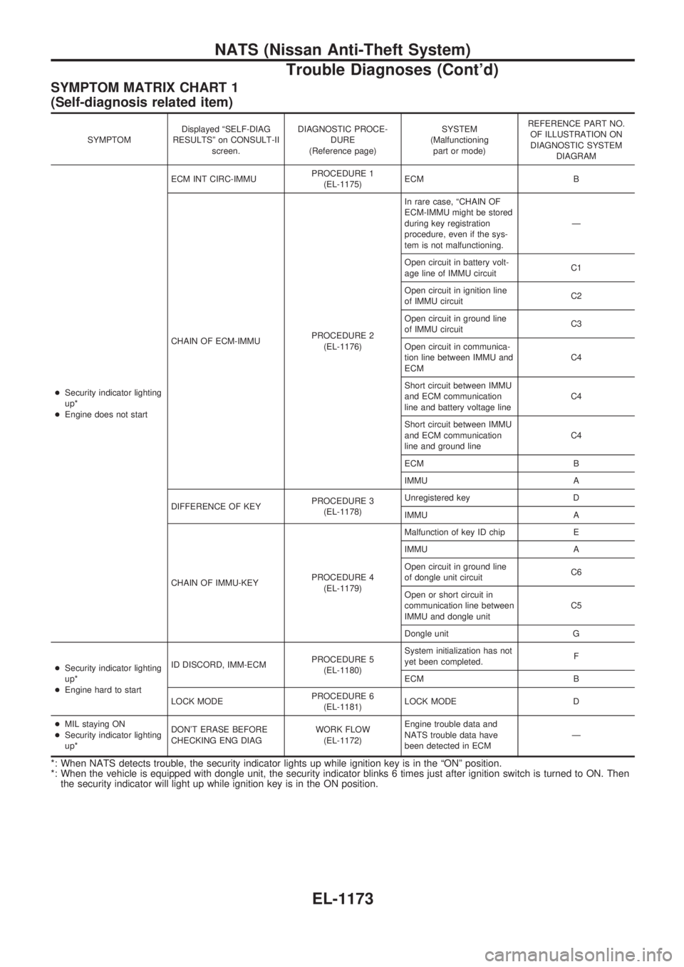
SYMPTOM MATRIX CHART 1
(Self-diagnosis related item)
SYMPTOMDisplayed ªSELF-DIAG
RESULTSº on CONSULT-II
screen.DIAGNOSTIC PROCE-
DURE
(Reference page)SYSTEM
(Malfunctioning
part or mode)REFERENCE PART NO.
OF ILLUSTRATION ON
DIAGNOSTIC SYSTEM
DIAGRAM
+Security indicator lighting
up*
+Engine does not startECM INT CIRC-IMMUPROCEDURE 1
(EL-1175)ECM B
CHAIN OF ECM-IMMUPROCEDURE 2
(EL-1176)In rare case, ªCHAIN OF
ECM-IMMU might be stored
during key registration
procedure, even if the sys-
tem is not malfunctioning.Ð
Open circuit in battery volt-
age line of IMMU circuitC1
Open circuit in ignition line
of IMMU circuitC2
Open circuit in ground line
of IMMU circuitC3
Open circuit in communica-
tion line between IMMU and
ECMC4
Short circuit between IMMU
and ECM communication
line and battery voltage lineC4
Short circuit between IMMU
and ECM communication
line and ground lineC4
ECM B
IMMU A
DIFFERENCE OF KEYPROCEDURE 3
(EL-1178)Unregistered key D
IMMU A
CHAIN OF IMMU-KEYPROCEDURE 4
(EL-1179)Malfunction of key ID chip E
IMMU A
Open circuit in ground line
of dongle unit circuitC6
Open or short circuit in
communication line between
IMMU and dongle unitC5
Dongle unit G
+Security indicator lighting
up*
+Engine hard to startID DISCORD, IMM-ECMPROCEDURE 5
(EL-1180)System initialization has not
yet been completed.F
ECM B
LOCK MODEPROCEDURE 6
(EL-1181)LOCK MODE D
+MIL staying ON
+Security indicator lighting
up*DON'T ERASE BEFORE
CHECKING ENG DIAGWORK FLOW
(EL-1172)Engine trouble data and
NATS trouble data have
been detected in ECMÐ
*: When NATS detects trouble, the security indicator lights up while ignition key is in the ªONº position.
*: When the vehicle is equipped with dongle unit, the security indicator blinks 6 times just after ignition switch is turned to ON. Then
the security indicator will light up while ignition key is in the ON position.
NATS (Nissan Anti-Theft System)
Trouble Diagnoses (Cont'd)
EL-1173
Page 692 of 1033
![NISSAN PATROL 2000 Electronic Repair Manual DIAGNOSTIC PROCEDURE 7
ªSECURITY IND. DOES NOT LIGHT UPº
Check 7.5A fuse [No.24, located in the
fuse block (J/B)].
OK
cNG
Replace fuse.
NATS INITIALIZATION
1) Install the 7.5A fuse.
2) Perform initi NISSAN PATROL 2000 Electronic Repair Manual DIAGNOSTIC PROCEDURE 7
ªSECURITY IND. DOES NOT LIGHT UPº
Check 7.5A fuse [No.24, located in the
fuse block (J/B)].
OK
cNG
Replace fuse.
NATS INITIALIZATION
1) Install the 7.5A fuse.
2) Perform initi](/manual-img/5/57367/w960_57367-691.png)
DIAGNOSTIC PROCEDURE 7
ªSECURITY IND. DOES NOT LIGHT UPº
Check 7.5A fuse [No.24, located in the
fuse block (J/B)].
OK
cNG
Replace fuse.
NATS INITIALIZATION
1) Install the 7.5A fuse.
2) Perform initialization with CON-
SULT-II.
For the operation of
initialization, refer to ªCON-
SULT-II operation manual
NATSº.
Turn ignition switch ªOFFº.
Start engine and turn ignition switch
ªOFFº.
Check the security ind. lighting.
NG
cOK
END
Check voltage between security ind. con-
nector terminal
V1and ground.
Voltage: Battery voltage
OK
cNG
Check harness for open or
short between fuse and
security ind.
CHECK INDICATOR LAMP.
OK
cNG
Repair harness.
CHECK NATS IMMU FUNCTION.
1. Connect NATS IMMU connector.
2. Disconnect security ind. connector.
3. Check continuity between NATS IMMU
terminal
V6and ground.
Continuity should exist intermit-
tently.
OK
cNG
NATS IMMU is malfunc-
tioning. Replace IMMU.
Perform initializa-
tion with CON-
SULT-II.
For the operation
of initialization,
refer to ªCON-
SULT-II operation
manual NATSº.
Check harness for open or short between
security indicator and NATS IMMU.
SEL931UA
SEL164X
.
.
.
.
.
.
.
.
.
NATS (Nissan Anti-Theft System)
Trouble Diagnoses (Cont'd)
EL-1182
Page 916 of 1033
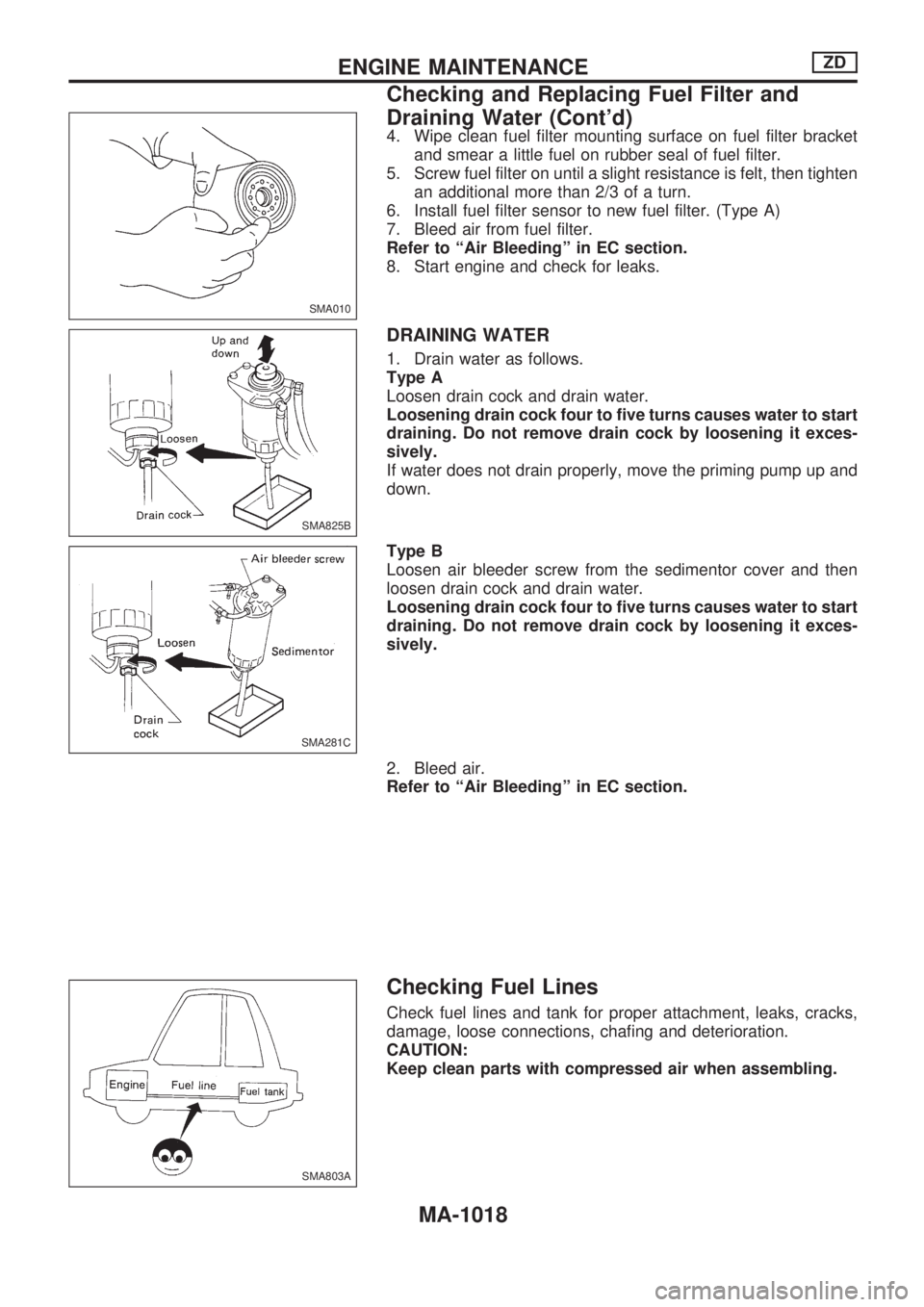
4. Wipe clean fuel filter mounting surface on fuel filter bracket
and smear a little fuel on rubber seal of fuel filter.
5. Screw fuel filter on until a slight resistance is felt, then tighten
an additional more than 2/3 of a turn.
6. Install fuel filter sensor to new fuel filter. (Type A)
7. Bleed air from fuel filter.
Refer to ªAir Bleedingº in EC section.
8. Start engine and check for leaks.
DRAINING WATER
1. Drain water as follows.
Type A
Loosen drain cock and drain water.
Loosening drain cock four to five turns causes water to start
draining. Do not remove drain cock by loosening it exces-
sively.
If water does not drain properly, move the priming pump up and
down.
Type B
Loosen air bleeder screw from the sedimentor cover and then
loosen drain cock and drain water.
Loosening drain cock four to five turns causes water to start
draining. Do not remove drain cock by loosening it exces-
sively.
2. Bleed air.
Refer to ªAir Bleedingº in EC section.
Checking Fuel Lines
Check fuel lines and tank for proper attachment, leaks, cracks,
damage, loose connections, chafing and deterioration.
CAUTION:
Keep clean parts with compressed air when assembling.
SMA010
SMA825B
SMA281C
SMA803A
ENGINE MAINTENANCEZD
Checking and Replacing Fuel Filter and
Draining Water (Cont'd)
MA-1018