2000 MITSUBISHI MONTERO service
[x] Cancel search: servicePage 607 of 1839

MITSUBISHI SC-Troubleshooting/On-vehicle Service13E-18
Terminal No.Signal nameNormal condition
Between terminal 13 and body earthEarthContinuity
Between terminal 26 and body earthEarth
Between terminal 31 and body earthEarth
ON-VEHICLE SERVICE
OPERATION TEST OF MITSUBISHI SC
1. Connect the MUT-
IIto the 16-pin diagnosis connector.
Caution
Turn the ignition switch to the LOCK (OFF) position
when connecting and disconnecting the MUT-
II.
2. Move the shift lever to the neutral
lever to the P range.
3. Start the engine.
4. Use the MUT-
IIto activate the Actuator Test (item No.05)
while depressing the accelerator pedal fully. Check that
the engine speed should decrease gradually.
Caution
Activate the Actuator Test for three seconds.
Release the accelerator pedal immediately after the
Actuator Test is complete, or the engine speed will
rise.
NOTE
During the Actuator Test, the SC-ECU transmits the signal,
which requests no torque and wide open throttle, to the
engine-ECU or engine-A/T-ECU for three seconds.
WHEEL SPEED SENSOR (FR) CHECK
Refer to Basic Manual GROUP 35B - On-vehicle service.
VEHICLE SPEED SENSOR CHECK
Refer to Basic Manual GROUP 54A - Combination Meter.
www.WorkshopManuals.co.uk
Purchased from www.WorkshopManuals.co.uk
Page 611 of 1839

13E-1
DIESEL FUEL
<4D5-STEPIII
>
CONTENTS
GENERAL 2.................................
Outline of Change 2............................
GENERAL INFORMATION 2...................
SERVICE SPECIFICATIONS 4.................
SEALANT 4..................................
SPECIAL TOOLS 5...........................
TROUBLESHOOTING 6.......................
ON-VEHICLE SERVICE 55....................
Injection Nozzle Check and Adjustment 55.........
Injection Timing Check and Adjustment 55.........
Idle Speed Check and Adjustment 55.............
Accelerator Pedal Position Sensor (APS)
Adjustment 56.................................
Control Relay Continuity Check 57................
Accelerator Pedal Position Sensor (APS)
Check 57......................................Idle Switch Check 58............................
Boost Air Temperature Sensor (Intake Air
Temperature Sensor) Check 58..................
Engine Coolant Temperature Sensor Check 59.....
Evacuation of Water from Fuel Filter 59............
Fuel Filter Cartridge Replacement 60..............
Evacuation of Air from Fuel Line 60...............
EGR Valve Position Sensor Check 60.............
Fuel Injection Pump Check 61....................
Throttle Solenoid Valve Check 62.................
Throttle Actuator Check 63......................
Variable Geometry Solenoid Valve Check 63.......
EGR Control Solenoid Valve Check 63............
FUEL INJECTION NOZZLE 64.................
FUEL INJECTION PUMP 64...................
CRANKSHAFT POSITION SENSOR 66.........
ENGINE-ECU 66.............................
www.WorkshopManuals.co.uk
Purchased from www.WorkshopManuals.co.uk
Page 612 of 1839

DIESEL FUEL <4D5-stepIII>-General/General Information13E-2
GENERAL
OUTLINE OF CHANGE
An electronically-controlled injection pump has been added in order to comply with Regulation STEP
III. Due to this, the following service procedures have been added.
GENERAL INFORMATION
The electronically-controlled fuel injection system consists of sensors which detect the condition of the
diesel engine, an engine-ECU which controls the system based on signals from these sensors, and actuators
which operate according to control commands from the engine-ECU.
The engine-ECU carries out operations such as fuel injection rate control, fuel injection timing control
and idle up control. In addition, the engine-ECU is equipped with several self-diagnosis functions which
make troubleshooting easier in the event that a problem develops.
FUEL INJECTION RATE CONTROL
The fuel injection completion timing is controlled by means of a solenoid-type spill valve to ensure that
the optimum amount of fuel is supplied to the engine in accordance with gradual changes in the engine
running condition.
Before fuel injection starts, the solenoid-type spill valve is on (energized), so that the valve is closed.
As the plunger turns and rises, fuel is sent out under pressure, and when the fuel flow rate reaches
the target value for fuel injection, the solenoid-type spill valve turns off. When the solenoid-type spill
valve turns off, the fuel under high pressure inside the plunger is leaked out into the pump chamber
and fuel injection is completed.
FUEL INJECTION TIMING CONTROL
The position of the injection pump timer piston is controlled so that fuel injection is carried out at the
optimum timing in accordance with the engine running condition.
The timer piston position is determined by duty control of the timing control solenoid valve which is located
in the line between the high-pressure chamber and the low-pressure chamber of the timer piston.
The fuel injection timing is advanced by increasing the control duty of the timing control solenoid valve.
IDLE SPEED CONTROL
Controlling the fuel injection rate in accordance with the engine running condition maintains the idle speed
at the optimum condition.
SELF-DIAGNOSIS FUNCTION
DWhen an abnormality is detected in any of the sensors or actuators, the engine warning lamp illuminates
to warn the driver.
DWhen an abnormality is detected in any of the sensors or actuators, a diagnosis code number
corresponding to the problem which occurred is output.
DThe RAM data relating to the sensors and actuators which is stored in the engine-ECU can be read
using the MUT-II. In addition, the actuators can be force-driven under certain conditions.
OTHER CONTROL FUNCTIONS
1. Power Supply Control
When the ignition switch is turned to ON, the relay turns on and power is supplied to components
such as the timing control solenoid valve.
2. Intake Air Throttle Control
When the engine-ECU detects an abnormality in any of the sensors or actuators, the throttle valve
is half opened to restrict the amount of intake air in order to prevent the vehicle from running away.
3. A/C Relay Control
Turns the compressor clutch of the A/C ON and OFF
4. Condenser Fan Motor Relay Control
Controls the condenser fan motor relay based on the A/C switch, engine coolant temperature and
vehicle speed input signals.
5. Glow Control
Refer to GROUP 16.
6. EGR Control
Refer to GROUP 17.
www.WorkshopManuals.co.uk
Purchased from www.WorkshopManuals.co.uk
Page 614 of 1839

DIESEL FUEL <4D5-stepIII>-Service Specifications/Sealant13E-4
SERVICE SPECIFICATIONS
ItemStandard value
Fuel injection initial pressure kPa14,710 - 15,490
Accelerator pedal position sensor reference voltage V0.985 - 1.085
Accelerator pedal position sensor resistance kΩ3.5 - 6.5
Boost air temperature sensor (Intake air temperature
)itkΩ
When the temperature is 20_C2.3 - 3.0p(p
sensor) resistance kΩWhen the temperature is 80_C0.30 - 0.42
Engine coolant temperature sensor resistance kΩWhen the temperature is 20_C2.1 - 2.7gp
When the temperature is 80_C0.26 - 0.36
Fuel cut solenoid valve resistanceΩ6.8 - 9.2
Timing control valve resistanceΩ10.8 - 11.2
Timer piston position sensor resistanceΩConnector terminals No. 1 - No. 2160 - 168pp
Connector terminals No. 1 - No. 380 - 84
Connector terminals No. 2 - No. 380 - 84
Control sleeve position sensor resistanceΩConnector terminals No. 4 - No. 1211.2 - 12.4p
Connector terminals No. 4 - No. 85.6 - 6.2
Connector terminals No. 8 - No. 125.6 - 6.2
GE actuator (electronic governor) resistanceΩConnector terminals No. 6 - No. 100.64 - 0.72
Fuel temperature sensor resistance kΩConnector terminals No. 7 - No. 111.4 - 2.6
Pump speed sensor resistance kΩ1.36 - 1.84
Throttle solenoid valve resistanceΩ36 - 44
SEALANT
ItemSpecified sealant
Engine coolant temperature sensor3M Nut Locking Part No. 4171 or equivalent
www.WorkshopManuals.co.uk
Purchased from www.WorkshopManuals.co.uk
Page 634 of 1839

DIESEL FUEL <4D5-stepIII>-Troubleshooting13E-24
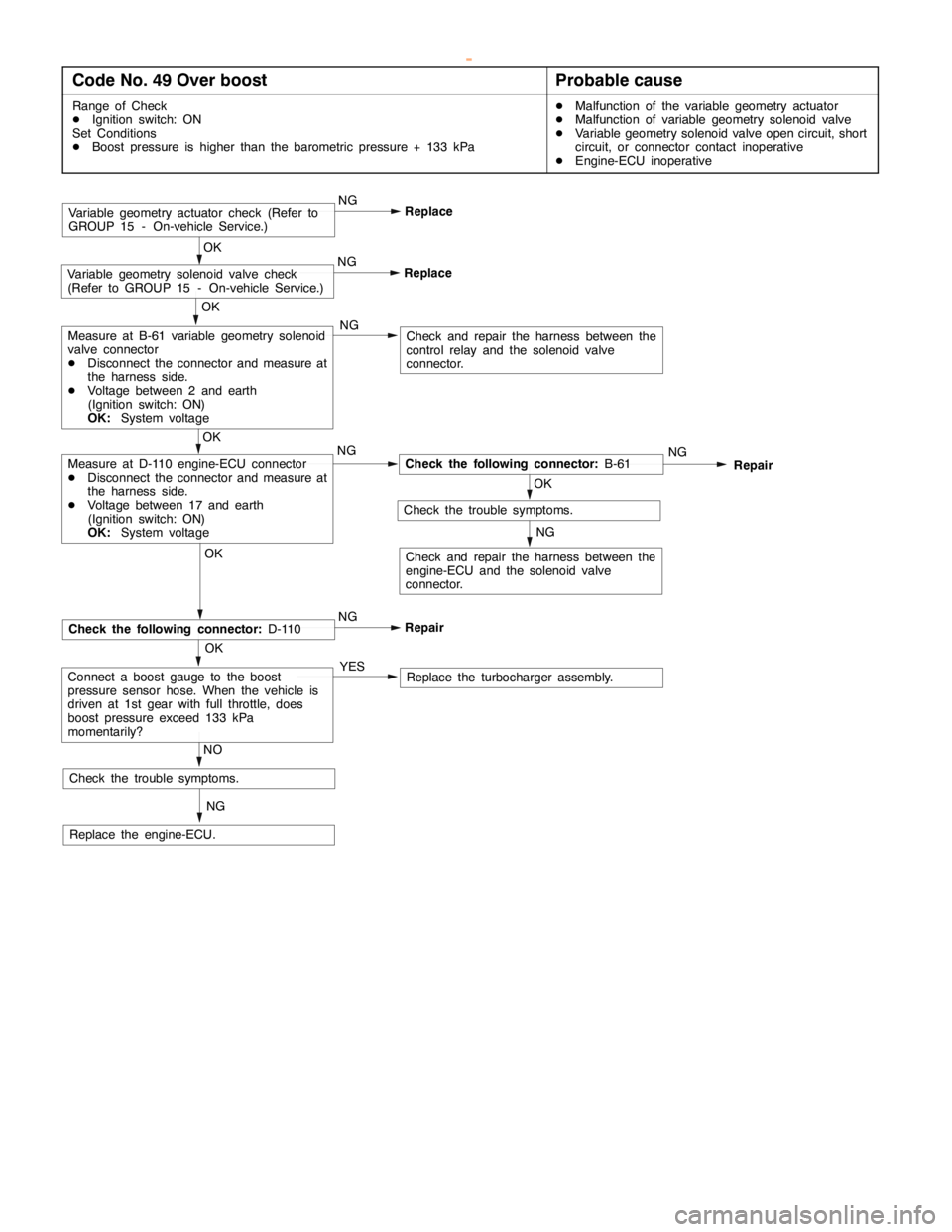
Code No. 49 Over boostProbable cause
Range of Check
DIgnition switch: ON
Set Conditions
DBoost pressure is higher than the barometric pressure + 133 kPaDMalfunction of the variable geometry actuator
DMalfunction of variable geometry solenoid valve
DVariable geometry solenoid valve open circuit, short
circuit, or connector contact inoperative
DEngine-ECU inoperative
OKOK
Check and repair the harness between the
control relay and the solenoid valve
connector.
Replace the engine-ECU.OK
ReplaceVariable geometry solenoid valve check
(Refer to GROUP 15 - On-vehicle Service.)
Check the trouble symptoms.NG
NG
Check the following connector:B-61NG
Repair
OK
Check the trouble symptoms.
NG
NGMeasure at D-110 engine-ECU connector
DDisconnect the connector and measure at
the harness side.
DVoltage between 17 and earth
(Ignition switch: ON)
OK:System voltageOK
Measure at B-61 variable geometry solenoid
valve connector
DDisconnect the connector and measure at
the harness side.
DVoltage between 2 and earth
(Ignition switch: ON)
OK:System voltage
Check and repair the harness between the
engine-ECU and the solenoid valve
connector.
ReplaceVariable geometry actuator check (Refer to
GROUP 15 - On-vehicle Service.)NG
OK
Repair
Check the following connector:D-110NG
NG
Replace the turbocharger assembly. YESConnect a boost gauge to the boost
pressure sensor hose. When the vehicle is
driven at 1st gear with full throttle, does
boost pressure exceed 133 kPa
momentarily?
NO
www.WorkshopManuals.co.uk
Purchased from www.WorkshopManuals.co.uk
Page 648 of 1839

DIESEL FUEL <4D5-stepIII>-Troubleshooting13E-38
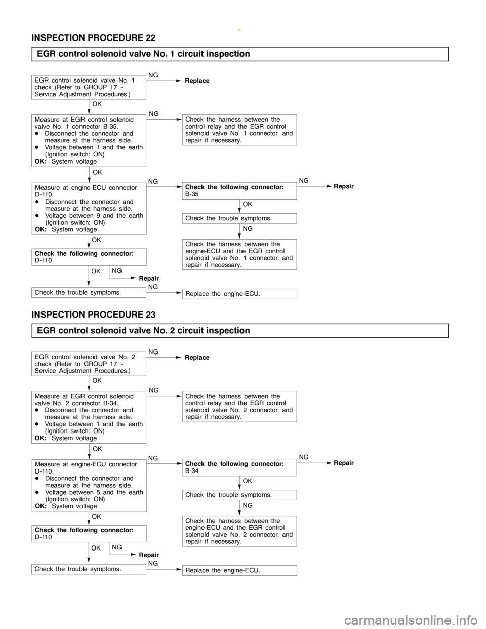
INSPECTION PROCEDURE 22
EGR control solenoid valve No. 1 circuit inspection
NG
Check the harness between the
engine-ECU and the EGR control
solenoid valve No. 1 connector, and
repair if necessary.
OK
Check the trouble symptoms.
OK
Measure at EGR control solenoid
valve No. 1 connector B-35.
DDisconnect the connector and
measure at the harness side.
DVoltage between 1 and the earth
(Ignition switch: ON)
OK:System voltage
NG
Check the following connector:
B-35NG
Repair NG
Check the harness between the
control relay and the EGR control
solenoid valve No. 1 connector, and
repair if necessary.
EGR control solenoid valve No. 1
check (Refer to GROUP 17 -
Service Adjustment Procedures.)NG
Replace
OK
Measure at engine-ECU connector
D-110.
DDisconnect the connector and
measure at the harness side.
DVoltage between 9 and the earth
(Ignition switch: ON)
OK:System voltage
NG
Replace the engine-ECU. NGCheck the trouble symptoms.OK
Repair
Check the following connector:
D-110OK
INSPECTION PROCEDURE 23
EGR control solenoid valve No. 2 circuit inspection
NG
Check the harness between the
engine-ECU and the EGR control
solenoid valve No. 2 connector, and
repair if necessary.
OK
Check the trouble symptoms.
OK
Measure at EGR control solenoid
valve No. 2 connector B-34.
DDisconnect the connector and
measure at the harness side.
DVoltage between 1 and the earth
(Ignition switch: ON)
OK:System voltage
NG
Check the following connector:
B-34NG
Repair NG
Check the harness between the
control relay and the EGR control
solenoid valve No. 2 connector, and
repair if necessary.
EGR control solenoid valve No. 2
check (Refer to GROUP 17 -
Service Adjustment Procedures.)NG
Replace
OK
Measure at engine-ECU connector
D-110.
DDisconnect the connector and
measure at the harness side.
DVoltage between 5 and the earth
(Ignition switch: ON)
OK:System voltage
NG
Replace the engine-ECU. NGCheck the trouble symptoms.OK
Repair
Check the following connector:
D-110OK
www.WorkshopManuals.co.uk
Purchased from www.WorkshopManuals.co.uk
Page 649 of 1839

DIESEL FUEL <4D5-stepIII>-Troubleshooting13E-39
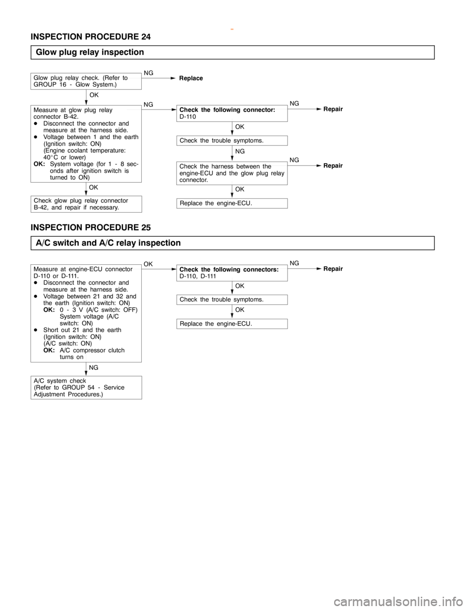
INSPECTION PROCEDURE 24
Glow plug relay inspection
NG
Replace the engine-ECU.
OK
Check the trouble symptoms.
OK
Measure at glow plug relay
connector B-42.
DDisconnect the connector and
measure at the harness side.
DVoltage between 1 and the earth
(Ignition switch: ON)
(Engine coolant temperature:
40_C or lower)
OK:System voltage (for 1 - 8 sec-
onds after ignition switch is
turned to ON)NGCheck the following connector:
D-110NG
Repair
Glow plug relay check. (Refer to
GROUP 16 - Glow System.)NG
Replace
Check glow plug relay connector
B-42, and repair if necessary.OK
OK
Check the harness between the
engine-ECU and the glow plug relay
connector.NG
Repair
INSPECTION PROCEDURE 25
A/C switch and A/C relay inspection
Replace the engine-ECU.
OK
Check the trouble symptoms.
Measure at engine-ECU connector
D-110 or D-111.
DDisconnect the connector and
measure at the harness side.
DVoltage between 21 and 32 and
the earth (Ignition switch: ON)
OK:0 - 3 V (A/C switch: OFF)
System voltage (A/C
switch: ON)
DShort out 21 and the earth
(Ignition switch: ON)
(A/C switch: ON)
OK:A/C compressor clutch
turns onOKCheck the following connectors:
D-110, D-111NG
Repair
A/C system check
(Refer to GROUP 54 - Service
Adjustment Procedures.)NGOK
www.WorkshopManuals.co.uk
Purchased from www.WorkshopManuals.co.uk
Page 678 of 1839

14-1
ENGINE COOLING
CONTENTS
GENERAL INFORMATION 2..................
SERVICE SPECIFICATIONS 2.................
LUBRICANT 2...............................
SEALANT 2..................................
ON-VEHICLE SERVICE 3.....................
Engine Coolant Leak Checking 3................
Radiator Cap Valve Opening Pressure Check
3 .............................................Engine Coolant Replacement 3..................
Concentration Measurement 5...................
COOLING FAN 6.............................
THERMOSTAT 8.............................
WATER PUMP 11............................
WATER HOSE AND WATER PIPE 15........
RADIATOR 20...............................
www.WorkshopManuals.co.uk
Purchased from www.WorkshopManuals.co.uk