Page 494 of 1839

DIESEL FUEL <4M4> -Service Specifications/Sealant13C-3
SERVICE SPECIFICATIONS
ItemStandard value
Accelerator pedal position sensor reference voltage V0.985 - 1.085
Accelerator pedal position sensor resistance kW3.5 - 6.5
Boost air temperature sensor (Intake air temperatureWhen the temperature is 20_C2.3 - 2.9
sensor) resistance kWWhen the temperature is 80_C0.30 - 0.39
Engine coolant temperature sensor resistance kWWhen the temperature is 20_C2.3 - 2.6
When the temperature is 80_C0.30 - 0.34
Fuel cut solenoid valve resistanceW6.8 - 9.2
Timing control valve resistanceW10.8 - 11.2
Timer piston position sensor resistanceWConnector terminals No.1 - No.2160 - 168
Connector terminals No.1 - No.380 - 84
Connector terminals No.2 - No.380 - 84
Control sleeve position sensor resistanceWConnector terminals No.4 - No.1211.2 - 12.4
Connector terminals No.4 - No.85.6 - 6.2
Connector terminals No.8 - No.125.6 - 6.2
GE actuator (electronic governor) resistanceWConnector terminals No.6 - No.100.64 - 0.72
Fuel temperature sensor resistance kWConnector terminals No.7 - No.111.4 - 2.6
Engine speed sensor resistance kW2.15
Main/sub throttle solenoid valve resistanceW36 - 44
SEALANT
ItemSpecified sealant
Engine coolant temperature sensor3M Nut Locking Part No.4171 or equivalent
www.WorkshopManuals.co.uk
Purchased from www.WorkshopManuals.co.uk
Page 513 of 1839

DIESEL FUEL <4M4> -TroubleshootingDIESEL FUEL <4M4> -Troubleshooting13C-22
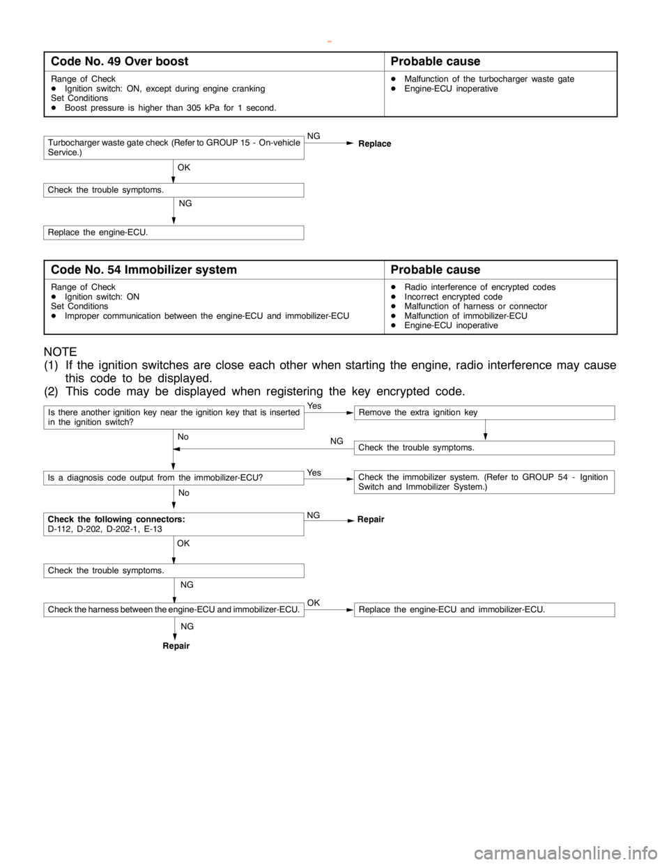
Code No. 49 Over boostProbable cause
Range of Check
DIgnition switch: ON, except duringenginecranking
Set Conditions
DBoost pressure is higher than 305 kPa for 1 second.DMalfunction of the turbocharger waste gate
DEngine-ECU inoperative
Turbocharger waste gate check (Refer to GROUP 15 - On-vehicle
Service.)NG
OK
Check the trouble symptoms.
NG
Replace the engine-ECU.Replace
Code No. 54 Immobilizer systemProbable cause
Range of Check
DIgnition switch: ON
Set Conditions
DImproper communication between the engine-ECU and immobilizer-ECUDRadio interference of encrypted codes
DIncorrect encrypted code
DMalfunction of harness or connector
DMalfunction of immobilizer-ECU
DEngine-ECU inoperative
NOTE
(1) If the ignition switches are close each other when starting the engine, radio interference may cause
this code to be displayed.
(2) This code may be displayed when registering the key encrypted code.
Is there another ignition key near the ignition key that is inserted
in the ignition switch?Ye sRemove the extra ignition key
No
Check the following connectors:
D-112, D-202, D-202-1, E-13NG
Repair
No
Is a diagnosis code output from the immobilizer-ECU?Ye sCheck the immobilizer system. (Refer to GROUP 54 - Ignition
Switch and Immobilizer System.)
NG OK
Check the trouble symptoms.
Check the harness between the engine-ECU and immobilizer-ECU.OKReplace the engine-ECU and immobilizer-ECU.
Check the trouble symptoms. NG
RepairNG
www.WorkshopManuals.co.uk
Purchased from www.WorkshopManuals.co.uk
Page 552 of 1839
Service Bulletins
Click on the applicable bookmark to select the Service Bulletin.
www.WorkshopManuals.co.uk
Purchased from www.WorkshopManuals.co.uk
Page 556 of 1839
13C-1
DIESEL FUEL
<4M4>
CONTENTS
GENERAL 2.................................
Outline of Changes 2...........................
SERVICE SPECIFICATIONS 2.................
TROUBLESHOOTING 2.......................ON-VEHICLE SERVICE 12....................
Throttle Body Assembly Check 12................
INJECTION PUMP 13.........................
www.WorkshopManuals.co.uk
Purchased from www.WorkshopManuals.co.uk
Page 557 of 1839
Page 564 of 1839

DIESEL FUEL <4M4> -Troubleshooting13C-9
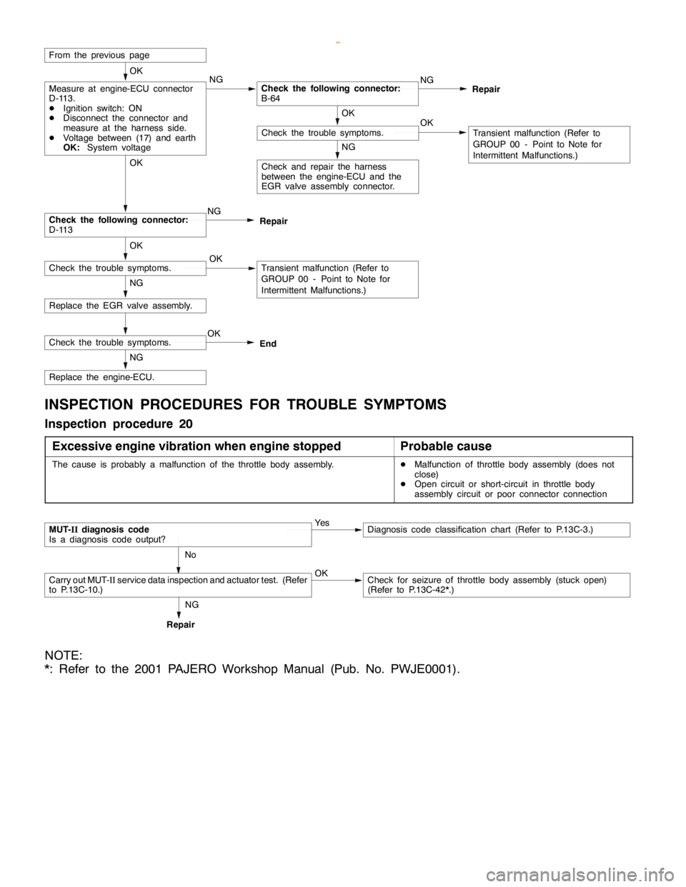
Replace the engine-ECU.
Replace the EGR valve assembly.NG
Check the following connector:
D-113NG OK
Check and repair the harness
between the engine-ECU and the
EGR valve assembly connector.
NG
OKCheck the trouble symptoms.
OK
Transient malfunction (Refer to
GROUP 00 - Point to Note for
Intermittent Malfunctions.)
From the previous page
NGMeasure at engine-ECU connector
D-113.
DIgnition switch: ON
DDisconnect the connector and
measure at the harness side.
DVoltage between (17) and earth
OK:System voltageCheck the following connector:
B-64NG
Repair OK
NG
OKCheck the trouble symptoms.Transient malfunction (Refer to
GROUP 00 - Point to Note for
Intermittent Malfunctions.) OKRepair
Check the trouble symptoms.OK
End
INSPECTION PROCEDURES FOR TROUBLE SYMPTOMS
Inspection procedure 20
Excessive engine vibration when engine stopped
Probable cause
The cause is probably a malfunction of the throttle body assembly.DMalfunction of throttle body assembly (does not
close)
DOpen circuit or short-circuit in throttle body
assembly circuit or poor connector connection
MUT-IIdiagnosis code
Is a diagnosis code output?Ye sDiagnosis code classification chart (Refer to P.13C-3.)
No
Carry out MUT-IIservice data inspection and actuator test. (Refer
to P.13C-10.)OKCheck for seizure of throttle body assembly (stuck open)
(Refer to P.13C-42*.)
RepairNG
NOTE:
*: Refer to the 2001 PAJERO Workshop Manual (Pub. No. PWJE0001).
www.WorkshopManuals.co.uk
Purchased from www.WorkshopManuals.co.uk
Page 590 of 1839

13E-1
MITSUBISHI STABILITY
CONTROL
(MITSUBISHI SC)
CONTENTS
GENERAL INFORMATION 2................
SERVICE SPECIFICATIONS 4..............
SPECIAL TOOLS 4........................
TROUBLESHOOTING 5....................
ON-VEHICLE SERVICE 18.................
Operation Test of MITSUBISHI SC 18.........Wheel Speed Sensor (FR) Check 18..........
Vehicle Speed Sensor Check 18..............
SC-ECU* 19...............................
G SENSOR 20.............................
WHEEL SPEED SENSOR (FR) 20..........
VEHICLE SPEED SENSOR 20..............
WARNINGS REGARDING SERVICING OF SUPPLEMENTAL RESTRAINT SYSTEM (SRS) EQUIPPED VEHICLES
WARNING!
(1) Improper service or maintenance of any component of the SRS, or any SRS-related component, can lead to personal
injury or death to service personnel (from inadvertent firing of the air bag) or to the driver and passenger (from rendering
the SRS inoperative).
(2) Service or maintenance of any SRS component or SRS-related component must be performed only at an authorized
MITSUBISHI dealer.
(3) MITSUBISHI dealer personnel must thoroughly review this manual, and especially its GROUP 52B - Supplemental
Restraint System (SRS) before beginning any service or maintenance of any component of the SRS or any SRS-related
component.
NOTE
The SRS includes the following components: front impact sensors, SRS-ECU, SRS warning lamp, air bag module, clock spring and
interconnecting wiring. Other SRS-related components (that may have to be removed/installed in connection with SRS service or
maintenance) are indicated in the table of contents by an asterisk (*).
www.WorkshopManuals.co.uk
Purchased from www.WorkshopManuals.co.uk
Page 603 of 1839

MITSUBISHI SC-Troubleshooting13E-14
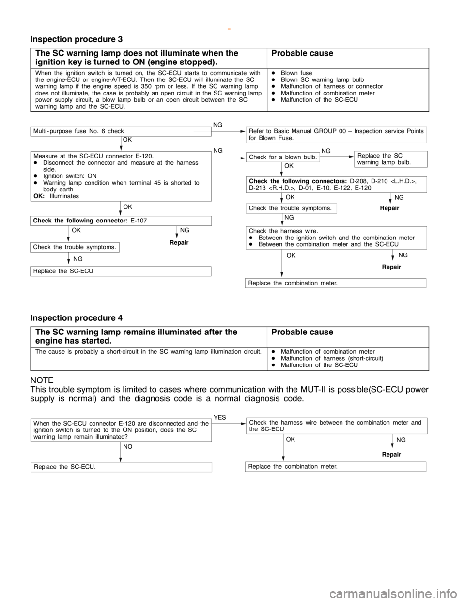
Inspection procedure 3
The SC warning lamp does not illuminate when the
ignition key is turned to ON (engine stopped).
Probable cause
When the ignition switch is turned on, the SC-ECU starts to communicate with
the engine-ECU or engine-A/T-ECU. Then the SC-ECU will illuminate the SC
warning lamp if the engine speed is 350 rpm or less. If the SC warning lamp
does not illuminate, the case is probably an open circuit in the SC warning lamp
power supply circuit, a blow lamp bulb or an open circuit between the SC
warning lamp and the SC-ECU.DBlown fuse
DBlown SC warning lamp bulb
DMalfunction of harness or connector
DMalfunction of combination meter
DMalfunction of the SC-ECU
NG
Replace the combination meter.
NG
Repair
OK
NG
Check for a blown bulb.Replace the SC
warning lamp bulb.
OK
NG
Repair
OK
Check the trouble symptoms.
Multi - purpose fuse No. 6 checkNGRefer to Basic Manual GROUP 00 – Inspection service Points
for Blown Fuse.
NG
Check the harness wire.
DBetween the ignition switch and the combination meter
DBetween the combination meter and the SC-ECU
OK
OK
Replace the SC-ECU
Check the following connector:
E-107
NG
RepairCheck the trouble symptoms.OK
NG
Check the following connectors:
D-208, D-210 ,
D-213 , D-01, E-10, E-122, E-120
Measure at the SC-ECU connector E-120.
DDisconnect the connector and measure at the harness
side.
DIgnition switch: ON
DWarning lamp condition when terminal 45 is shorted to
body earth
OK:
Illuminates
Inspection procedure 4
The SC warning lamp remains illuminated after the
engine has started.
Probable cause
The cause is probably a short-circuit in the SC warning lamp illumination circuit.DMalfunction of combination meter
DMalfunction of harness (short-circuit)
DMalfunction of the SC-ECU
NOTE
This trouble symptom is limited to cases where communication with the MUT-II is possible(SC-ECU power
supply is normal) and the diagnosis code is a normal diagnosis code.
When the SC-ECU connector E-120 are disconnected and the
ignition switch is turned to the ON position, does the SC
warning lamp remain illuminated?YES
NO
Replace the SC-ECU.Replace the combination meter.
NG
Repair
OK
Check the harness wire between the combination meter and
the SC-ECU
www.WorkshopManuals.co.uk
Purchased from www.WorkshopManuals.co.uk