2000 MITSUBISHI MONTERO service
[x] Cancel search: servicePage 248 of 1839
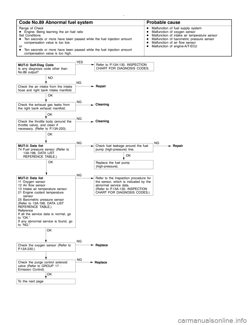
GDI -Troubleshooting
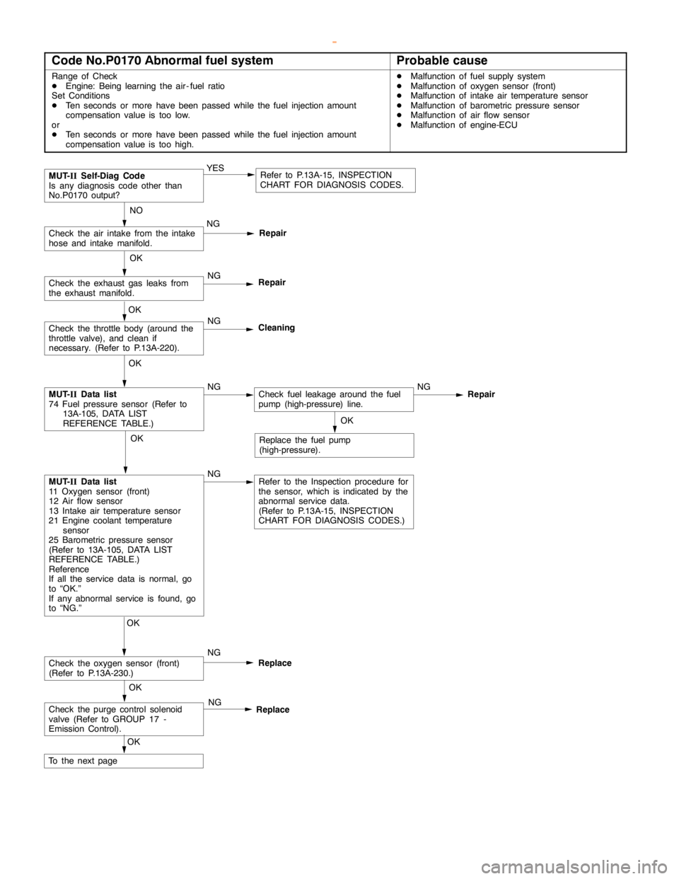
Code No.P0170 Abnormal fuel systemProbable cause
Range of Check
DEngine: Being learning the air - fuel ratio
Set Conditions
DTen seconds or more havebeenpassed while the fuel injection amount
compensation value is too low.
or
DTen seconds or more havebeenpassed while the fuel injection amount
compensation value is too high.DMalfunction of fuel supply system
DMalfunction of oxygen sensor (front)
DMalfunction of intake air temperature sensor
DMalfunction of barometric pressure sensor
DMalfunction of air flow sensor
DMalfunction of engine-ECU
Repair
OK
MUT-
IIData list
74 Fuel pressure sensor (Refer to
13A-105, DATA LIST
REFERENCE TABLE.)NGCheck fuel leakage around the fuel
pump (high-pressure) line.NG
NO
Check the air intake from the intake
hose and intake manifold.NG
Repair
OK
Check the oxygen sensor (front)
(Refer to P.13A-230.)NG
Replace
MUT-
IISelf-Diag Code
Is any diagnosis code other than
No.P0170 output?YESRefer to P.13A-15, INSPECTION
CHART FOR DIAGNOSIS CODES.
OK
Check the exhaust gas leaks from
the exhaust manifold.NG
Repair
OK
Check the throttle body (around the
throttle valve), and clean if
necessary. (Refer to P.13A-220).NG
Cleaning
OK
MUT-
IIData list
11 Oxygen sensor (front)
12 Air flow sensor
13 Intake air temperature sensor
21 Engine coolant temperature
sensor
25 Barometric pressure sensor
(Refer to 13A-105, DATA LIST
REFERENCE TABLE.)
Reference
If all the service data is normal, go
to “OK.”
If any abnormal service is found, go
to “NG.”NGRefer to the Inspection procedure for
the sensor, which is indicated by the
abnormal service data.
(Refer to P.13A-15, INSPECTION
CHART FOR DIAGNOSIS CODES.)OK
Replace the fuel pump
(high-pressure).
Check the purge control solenoid
valve (Refer to GROUP 17 -
Emission Control).NG
Replace
OK
To the nextpageOK
www.WorkshopManuals.co.uk
Purchased from www.WorkshopManuals.co.uk
Page 269 of 1839

GDI -Troubleshooting
Code No.P0301 No.1 cylinder misfire detected.
Code No.P0302 No.2 cylinder misfire detected.
Code No.P0303 No.3 cylinder misfire detected.
Code No.P0304 No.4 cylinder misfire detected.
Code No.P0305 No.5 cylinder misfire detected.Probable cause
Range of Check
DThe enginespeed is 500 - 4,500 r/min.
DWhile the engine is runningexcept deceleration and sudden acceleration.
Set Conditions
DThe number of misfires exceeds a predetermined number per 200engine
revolutions (Misfire has occurred in only one cylinder).
or
DThe number of misfires exceeds a predetermined number per 100engine
revolutions (Misfire has occurred in only one cylinder).DMalfunction of the ignition system
DAbnormal compression
DMalfunction of injector
DMalfunction of engine-ECU
NG
Check the harness wire between the
ignition coil and the engine-ECU.
NG
Replace
NG
Repair
(2) NG
OK
Check the ignition failure sensor
(Refer to GROUP 16 - Ignition
System.)
OK
Check the harness wire between the
ignition coil and the earth, and repair
if necessary. (3) NG
OK
Measure at ignition coil connectors
B-101, B-108, B-112, B-113, B-116,
B-119.
DDisconnect the connector and
measure at the harness side.
(1) The voltage between terminal 1
and earth
(Ignition switch: ON)
OK:
System voltage
(2) The voltage between terminal 3
and earth
(Engine: cranking)
OK:
0.5 - 4.0 V
(3) The resistance between terminal
2 and earth
OK:
2Wor less(1) NGCheck the following connectors:
B-04, B-107, D-208, D-223NG
Repair
Check the ignition coil (Refer to
GROUP 16 - Ignition System.)
Check the compression pressure.
(Refer to GROUP 11A - On-vehicle
Service.)Repair
Replace the engine-ECU.
OK
Check the harness wire between the
ignition coil and the ignition failure
sensor, and between the ignition coil
and the ignition failure sensor.
NG
Repair
OK
NGNG
Repair
OKReplace
NG
Check the spark plugs.
Check the trouble symptoms.
OK
Check the trouble symptoms.NGReplace the engine-ECU.
Check the following connectors:
B-101, B-108, B-112, B-113, B-116,
B-119
Check the following connector:
B-107, D-116
OK
www.WorkshopManuals.co.uk
Purchased from www.WorkshopManuals.co.uk
Page 308 of 1839
GDI -Troubleshooting
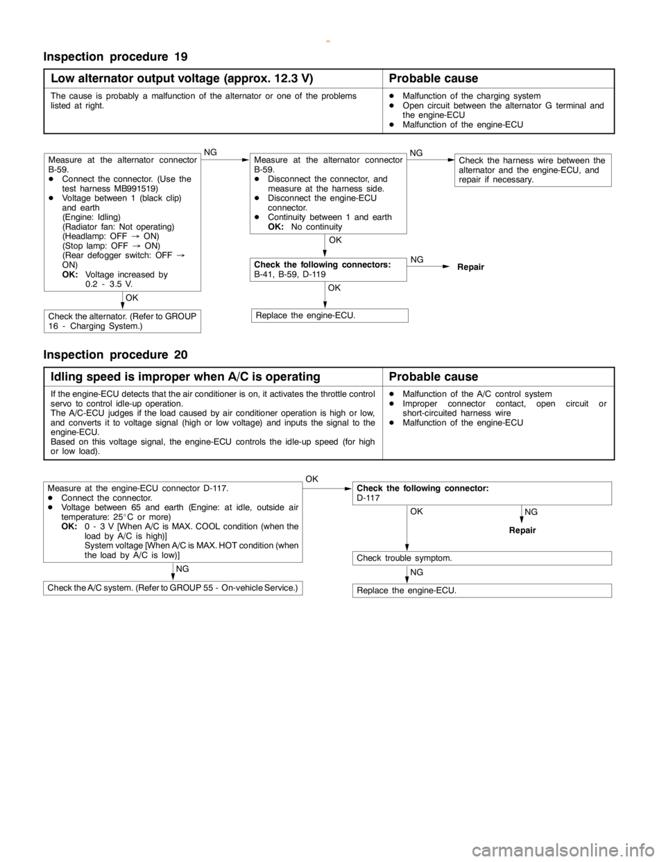
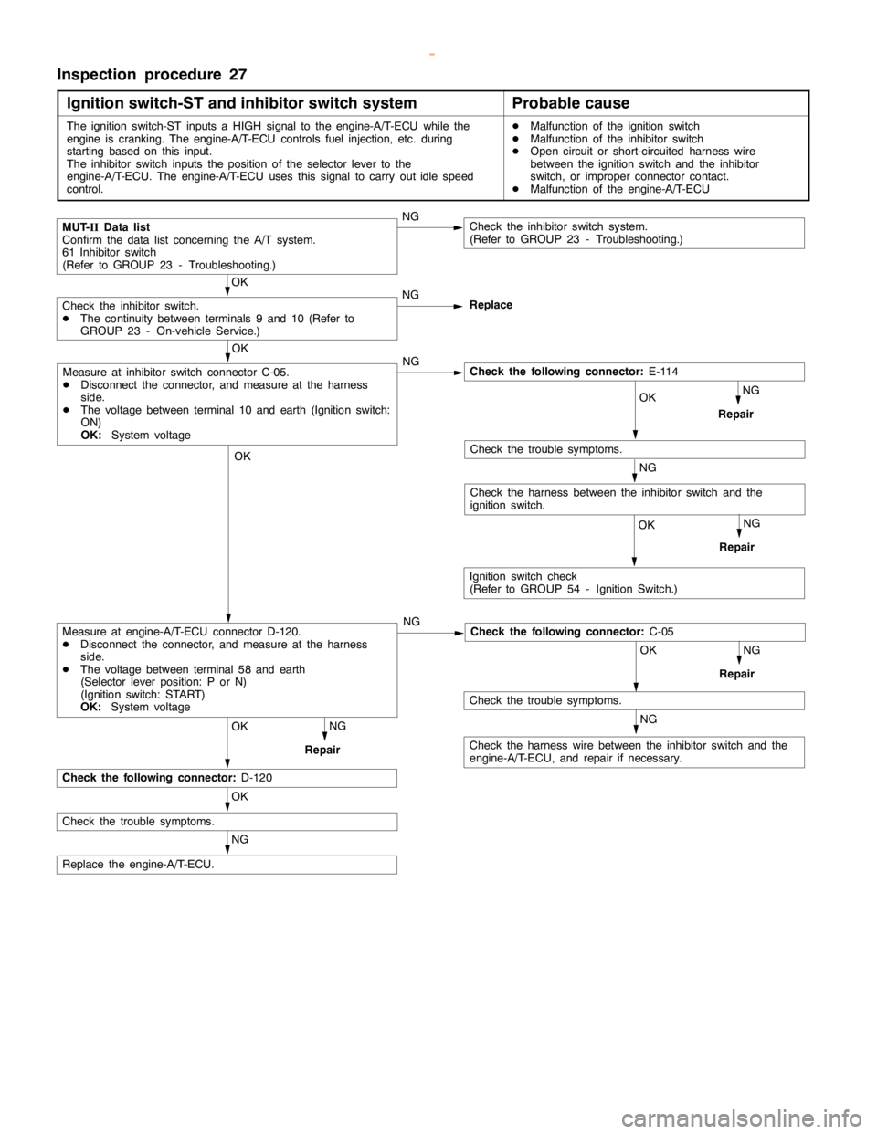
Inspection procedure 19
Low alternator output voltage (approx.12.3 V)
Probable cause
The cause is probably a malfunction of the alternator or one of the problems
listed at right.DMalfunction of the charging system
DOpen circuit between the alternator G terminal and
the engine-ECU
DMalfunction of the engine-ECU
NG
Repair
OK
Replace the engine-ECU.
OK
Check the alternator. (Refer to GROUP
16 - Charging System.)
OK
Check the following connectors:
B-41, B-59, D-119
Measure at the alternator connector
B-59.
DConnect the connector. (Use the
test harness MB991519)
DVoltage between 1 (black clip)
and earth
(Engine: Idling)
(Radiator fan: Not operating)
(Headlamp: OFF®ON)
(Stoplamp: OFF®ON)
(Rear defogger switch: OFF®
ON)
OK:
Voltage increased by
0.2 - 3.5 V.NGMeasure at the alternator connector
B-59.
DDisconnect the connector, and
measure at the harness side.
DDisconnect the engine-ECU
connector.
DContinuity between 1 and earth
OK:
No continuityNGCheck the harness wire between the
alternator and the engine-ECU, and
repair if necessary.
Inspection procedure 20
Idling speed is improper when A/C is operating
Probable cause
If the engine-ECU detects that the air conditioner is on, it activates the throttle control
servo to control idle-up operation.
The A/C-ECU judges if theloadcaused by air conditioner operation ishigh or low,
and converts it to voltage signal (high or low voltage) and inputs the signal to the
engine-ECU.
Based on this voltage signal, the engine-ECU controls the idle-up speed (forhigh
or low load).DMalfunction of the A/C control system
DImproper connector contact,opencircuit or
short-circuited harness wire
DMalfunction of the engine-ECU
NG
Repair
Measure at the engine-ECU connector D-117.
DConnect the connector.
DVoltage between 65 and earth (Engine: at idle, outside air
temperature: 25_C or more)
OK:
0 - 3 V [When A/C is MAX. COOL condition (when the
load by A/C is high)]
System voltage [When A/C is MAX. HOT condition (when
the load by A/C islow)]OKCheck the following connector:
D-117
OK
Check trouble symptom.
NG
Replace the engine-ECU.
NG
Check the A/C system. (Refer to GROUP 55 - On-vehicle Service.)
www.WorkshopManuals.co.uk
Purchased from www.WorkshopManuals.co.uk
Page 316 of 1839
GDI -Troubleshooting
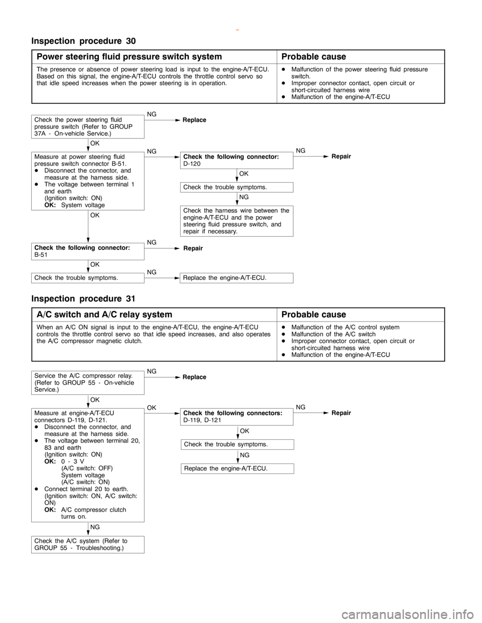
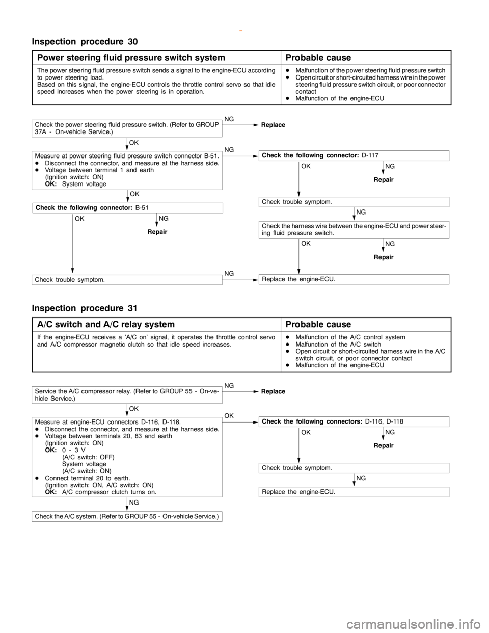
Inspection procedure 30
Power steering fluid pressure switch system
Probable cause
The power steering fluid pressure switch sends a signal to the engine-ECU according
to power steering load.
Based on this signal, the engine-ECU controls the throttle control servo so thatidle
speed increases when the power steering is in operation.DMalfunction of the power steering fluid pressure switch
DOpen circuit or short-circuited harness wire in the power
steering fluid pressure switch circuit, or poor connector
contact
DMalfunction of the engine-ECU
NG
NG
RepairOK
Replace the engine-ECU.
NG
Repair
Check the power steering fluid pressure switch. (Refer to GROUP
37A - On-vehicle Service.)NG
Replace
OK
Measure at power steering fluid pressure switch connector B-51.
DDisconnect the connector, and measure at the harness side.
DVoltage between terminal 1 and earth
(Ignition switch: ON)
OK:
System voltageNGCheck the following connector:
D-117
OK
Check trouble symptom.
Check the harness wire between the engine-ECU and power steer-
ing fluid pressure switch.NG
RepairOK
OK
Check the following connector:
B-51
Check trouble symptom.NG
Inspection procedure 31
A/C switch and A/C relay system
Probable cause
If the engine-ECU receives a ‘A/C on’ signal, it operates the throttle control servo
and A/C compressor magnetic clutch so thatidlespeed increases.DMalfunction of the A/C control system
DMalfunction of the A/C switch
DOpen circuit or short-circuited harness wire in the A/C
switch circuit, or poor connector contact
DMalfunction of the engine-ECU
NG
NG
RepairOK
Check trouble symptom.
NG
Replace the engine-ECU.
Service the A/C compressor relay. (Refer to GROUP 55 - On-ve-
hicle Service.)NG
Replace
OK
Measure at engine-ECU connectors D-116, D-118.
DDisconnect the connector, and measure at the harness side.
DVoltage between terminals 20, 83 and earth
(Ignition switch: ON)
OK:
0-3V
(A/C switch: OFF)
System voltage
(A/C switch: ON)
DConnect terminal 20 to earth.
(Ignition switch: ON, A/C switch: ON)
OK:
A/C compressor clutch turns on.OKCheck the following connectors:
D-116, D-118
Check the A/C system. (Refer to GROUP 55 - On-vehicle Service.)
www.WorkshopManuals.co.uk
Purchased from www.WorkshopManuals.co.uk
Page 341 of 1839

Page 374 of 1839
Page 405 of 1839
Page 408 of 1839
