2000 MITSUBISHI MONTERO service
[x] Cancel search: servicePage 926 of 1839
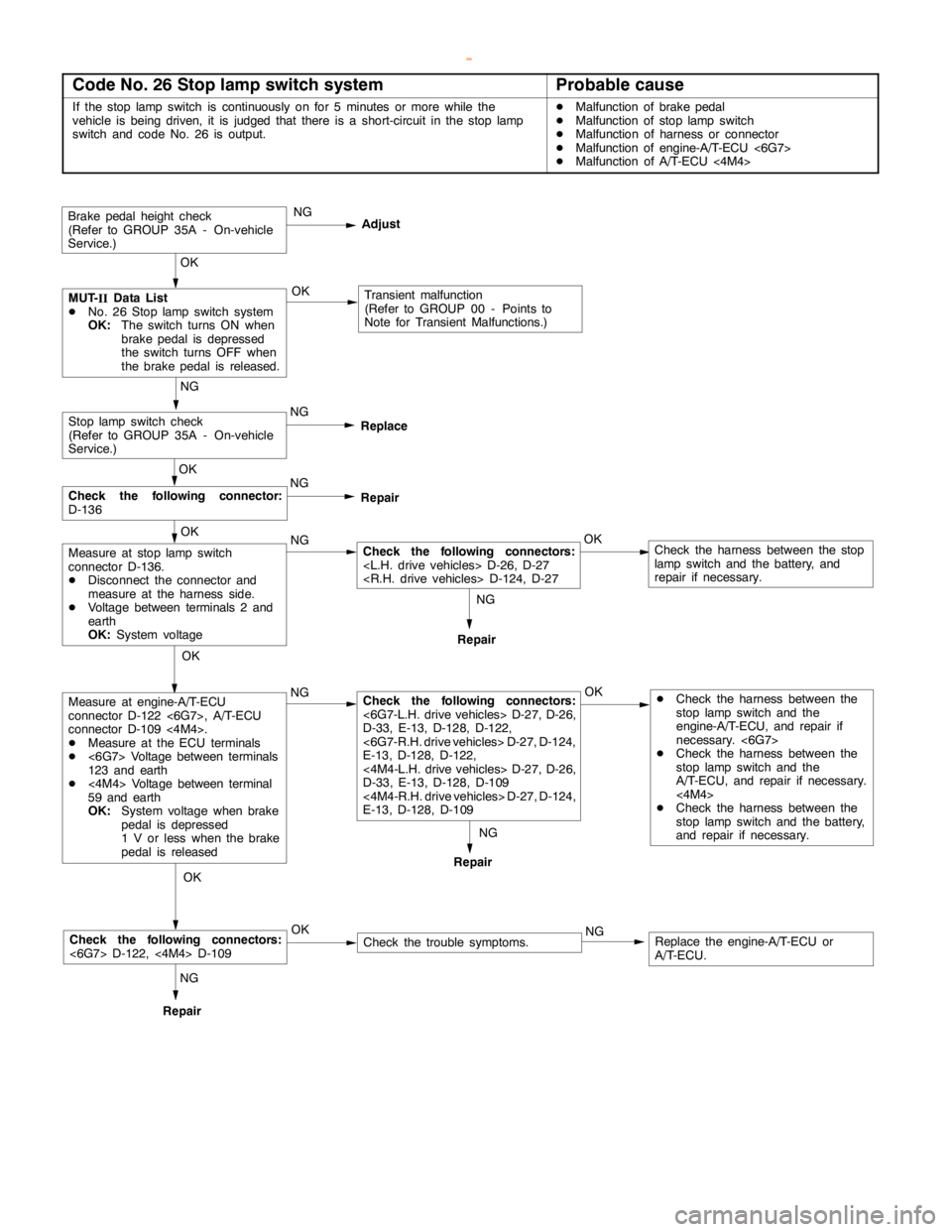
Page 946 of 1839

Page 960 of 1839
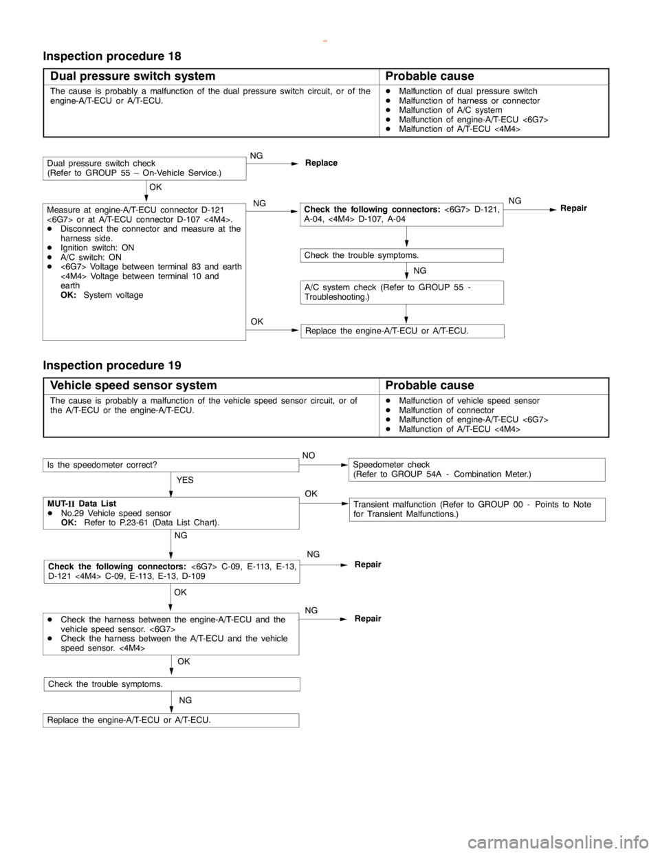
Page 974 of 1839
AUTOMATIC TRANSMISSION -Troublehshooting
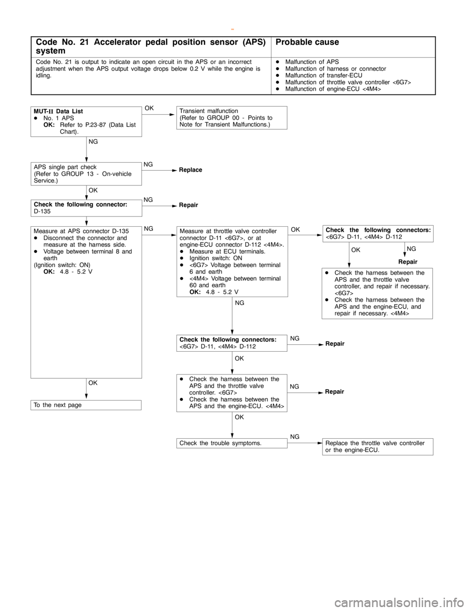
Code No. 21 Accelerator pedal position sensor (APS)
systemProbable cause
Code No. 21 is output to indicate anopencircuit in the APS or an incorrect
adjustment when the APS output voltage drops below 0.2 V while theengine is
idling.DMalfunction of APS
DMalfunction of harness or connector
DMalfunction of transfer-ECU
DMalfunction of throttle valve controller <6G7>
DMalfunction of engine-ECU <4M4>
NGNG
NG
Repair
MUT-
IIData List
DNo. 1 APS
OK:Refer to P.23-87 (Data List
Chart).
NG
ReplaceAPS single part check
(Refer to GROUP 13 - On-vehicle
Service.)
OK
NG
Repair
OK
Check the following connector:
D-135
OK
DCheck the harness between the
APS and the throttle valve
controller, and repair if necessary.
<6G7>
DCheck the harness between the
APS and the engine-ECU, and
repair if necessary.<4M4> OK
Check the following connectors:
<6G7> D-11,<4M4> D-112
Repair
NG
Repair
NG
Repair
OK
DCheck the harness between the
APS and the throttle valve
controller. <6G7>
DCheck the harness between the
APS and the engine-ECU. <4M4>
OK
Check the following connectors:
<6G7> D-11,<4M4> D-112
Measure at throttle valve controller
connector D-11 <6G7>, or at
engine-ECU connector D-112 <4M4>.
DMeasure at ECU terminals.
DIgnition switch: ON
D<6G7> Voltage between terminal
6 and earth
D<4M4> Voltage between terminal
60 and earth
OK:4.8 - 5.2 V
NGNG
NGCheck the trouble symptoms.Replace the throttle valve controller
or the engine-ECU.
OK
Measure at APS connector D-135
DDisconnect the connector and
measure at the harness side.
DVoltage between terminal 8 and
earth
(Ignition switch: ON)
OK:4.8 - 5.2 V
To the nextpage
Transient malfunction
(Refer to GROUP 00 - Points to
Note for Transient Malfunctions.)
OK
www.WorkshopManuals.co.uk
Purchased from www.WorkshopManuals.co.uk
Page 975 of 1839
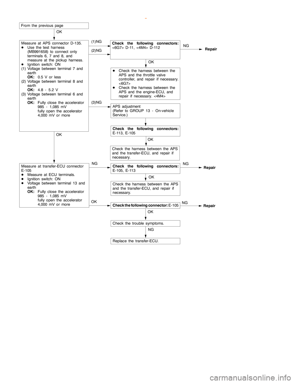
AUTOMATIC TRANSMISSION -Troublehshooting
OKOK OK
NG
NG
NG(1)NGCheck the following connectors:
<6G7> D-11,<4M4> D-112
Repair OK
DCheck the harness between the
APS and the throttle valve
controller, and repair if necessary.
<6G7>
DCheck the harness between the
APS and the engine-ECU, and
repair if necessary.<4M4> OK (2)NG
Measure at transfer-ECU connector
E-105
DMeasure at ECU terminals.
DIgnition switch: ON
DVoltage between terminal 13 and
earth
OK:Fully close the accelerator
985 - 1,085 mV
fullyopen the accelerator
4,000 mV or more
Check the following connector:E-105
Check the trouble symptoms.OK
Check the following connectors:
E-105, E-113 NG
Replace the transfer-ECU. OK
NGRepair
Check the harness between the APS
and the transfer-ECU, and repair if
necessary.
Check the harness between the APS
and the transfer-ECU, and repair if
necessary.
From the previouspage
(3)NG
Measure at APS connector D-135.
DUse the test harness
(MB991658) to connect only
terminals 6, 7 and 8, and
measure at the pickup harness.
DIgnition switch: ON
(1) Voltage between terminal 7 and
earth
OK:0.5 V or less
(2) Voltage between terminal 8 and
earth
OK:4.8 - 5.2 V
(3) Voltage between terminal 6 and
earth
OK:Fully close the accelerator
985 - 1,085 mV
fullyopen the accelerator
4,000 mV or more
APS adjustment
(Refer to GROUP 13 - On-vehicle
Service.)
Check the following connectors:
E-113, E-105
Repair
www.WorkshopManuals.co.uk
Purchased from www.WorkshopManuals.co.uk
Page 983 of 1839
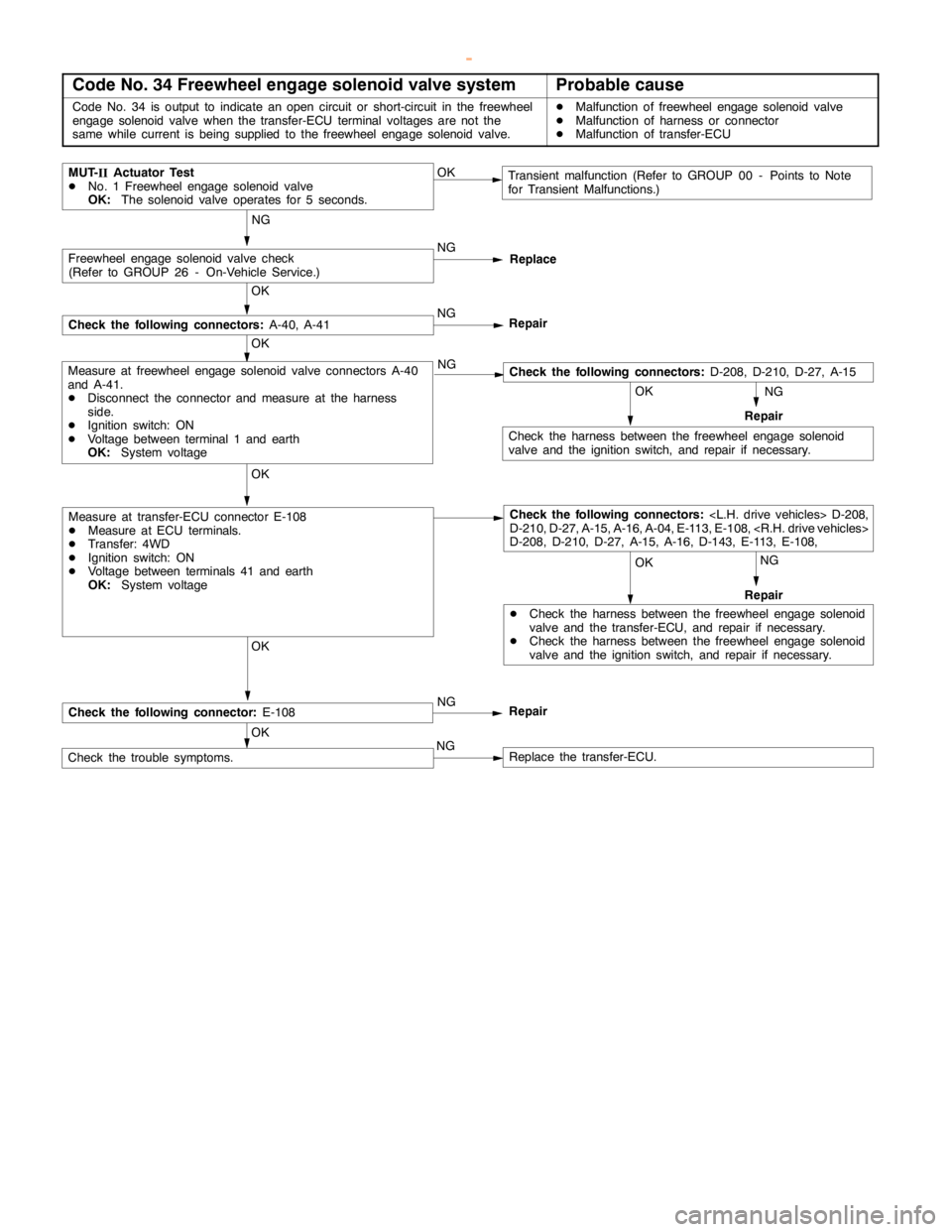
AUTOMATIC TRANSMISSION -Troublehshooting
Code No. 34 Freewheel engage solenoid valve systemProbable cause
Code No. 34 is output to indicate anopencircuit or short-circuit in the freewheel
engage solenoidvalve when the transfer-ECU terminal voltages are not the
same while current isbeing supplied to the freewheel engage solenoidvalve.DMalfunction of freewheel engage solenoidvalve
DMalfunction of harness or connector
DMalfunction of transfer-ECU
NG
NG
MUT-
IIActuator Test
DNo. 1 Freewheel engage solenoidvalve
OK:The solenoid valve operates for 5 seconds.Transient malfunction (Refer to GROUP 00 - Points to Note
for Transient Malfunctions.) OK
OK OK OKNG
DCheck the harness between the freewheelengage solenoid
valve and the transfer-ECU, and repair if necessary.
DCheck the harness between the freewheelengage solenoid
valve and the ignition switch, and repair if necessary.Repair
Check the harness between the freewheelengage solenoid
valve and the ignition switch, and repair if necessary.
OK OK
OK
NG
Check the trouble symptoms.Replace the transfer-ECU.
Measure at transfer-ECU connector E-108
DMeasure at ECU terminals.
DTransfer: 4WD
DIgnition switch: ON
DVoltage between terminals 41 and earth
OK:System voltage
Measure at freewheel engage solenoidvalve connectors A-40
and A-41.
DDisconnect the connector and measure at the harness
side.
DIgnition switch: ON
DVoltage between terminal 1 and earth
OK:System voltageNG
Replace
NG
Repair
Freewheel engage solenoidvalve check
(Refer to GROUP 26 - On-Vehicle Service.)
Check the following connectors:A-40, A-41
Repair NG
Check the following connector:E-108
NG
Repair
OK
Check the following connectors:
D-210, D-27, A-15, A-16, A-04, E-113, E-108,
D-208, D-210, D-27, A-15, A-16, D-143, E-113, E-108,
Check the following connectors:D-208, D-210, D-27, A-15
www.WorkshopManuals.co.uk
Purchased from www.WorkshopManuals.co.uk
Page 1001 of 1839

AUTOMATIC TRANSMISSION -On-vehicle Service23-100
Specified lubricant:
Hypoid gear oil SAE 75W-90 or 75W-85W
conforming to API GL-4
Oil level: 2.8 L
4. Install the oil filler plug, and tighten it to the specified
torque.
Tightening torque: 32±
2N×
m
www.WorkshopManuals.co.uk
Purchased from www.WorkshopManuals.co.uk
Page 1008 of 1839

AUTOMATIC TRANSMISSION -On-vehicle ServiceAUTOMATIC TRANSMISSION -On-vehicle Service23-107
HYDRAULIC PRESSURE TEST DIAGNOSIS TABLE
SymptomProblem location
All hydraulic pressures are too highMalfunction of regulator valve
All hydraulic pressures are too lowMalfunction of oil pump
Blocked oil filter
Blocked oil cooler
Malfunction of regulator valve
Malfunction of relief valve
Incorrect valve body installation
Abnormal hydraulic pressure in R range
onlyMalfunction of regulator valve
Abnormal hydraulic pressure in 3rd or 4th
onlyMalfunction of regulator valve
Malfunction of switch bulb
Abnormal UD pressure onlyMalfunction of oil seal K, L, M or Q
Malfunction of underdrive solenoid valve
Malfunction of underdrive pressure control valve
Abnormality with check ball
Blocked orifices
Incorrect valve body installation
Abnormal REV pressure onlyMalfunction of oil seal A, B or C
Abnormality with check ball
Blocked orifices
Incorrect valve body installation
Abnormal OD pressure onlyMalfunction of oil seal D, E or F
Malfunction of overdrive solenoid valve
Malfunction of overdrive pressure control valve
Abnormality with check ball
Blocked orifices
Incorrect valve body installation
Abnormal DIR pressure onlyMalfunction of oil seal R, S or T
Malfunction of low & reverse solenoid valve (also used for the direct
clutch)
Malfunction of low & reverse pressure control valve
Malfunction of switch bulb
Malfunction of fail-safe valve C
Blocked orifices
Incorrect valve body installation
Abnormal LR pressure onlyMalfunction of oil seal I, J or P
Malfunction of low & reverse solenoid valve (also used for the direct
clutch)
Malfunction of low & reverse pressure control valve
Malfunction of switch bulb
Malfunction of fail-safe valve A
Abnormality with check ball
Blocked orifices
Incorrect valve body installation
Abnormal 2ND pressure onlyMalfunction of oil seal G, H or O
Malfunction of second solenoid valve
Malfunction of second pressure control valve
Malfunction of fail-safe valve B
Blocked orifices
Incorrect valve body installation
www.WorkshopManuals.co.uk
Purchased from www.WorkshopManuals.co.uk