2000 MITSUBISHI MONTERO service
[x] Cancel search: servicePage 1223 of 1839
BASIC BRAKE SYSTEM -Troubleshooting35A-15
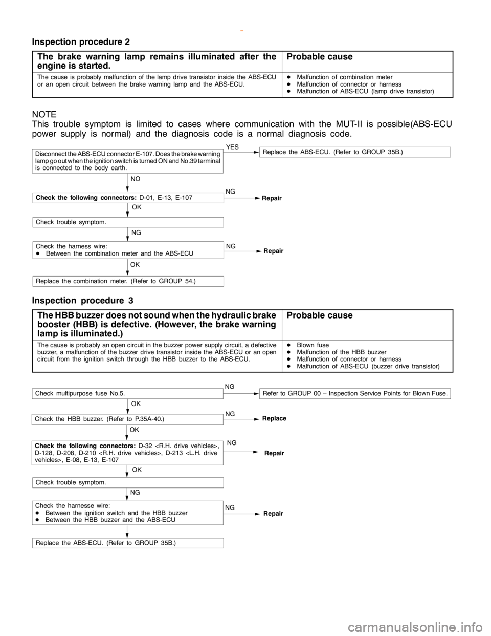
Inspection procedure 2
The brake warning lamp remains illuminated after the
engine is started.
Probable cause
The cause is probably malfunction of thelampdrive transistor inside the ABS-ECU
or an opencircuit between the brake warninglamp and theABS-ECU.DMalfunction of combination meter
DMalfunction of connector or harness
DMalfunction of ABS-ECU (lamp drive transistor)
NOTE
This trouble symptom is limited to cases where communication with the MUT-II is possible(ABS-ECU
power supply is normal) and the diagnosis code is a normal diagnosis code.
Repair NG
Repair
Replace the combination meter. (Refer to GROUP 54.)
OK
YESReplace the ABS-ECU. (Refer to GROUP 35B.)
NO
Disconnect the ABS-ECU connector E-107. Does the brake warning
lamp go outwhen the ignition switch is turned ON and No.39 terminal
is connected to the body earth.
OK
Check the following connectors:
D-01, E-13, E-107
Check trouble symptom.
Check the harness wire:
DBetween the combination meter and the ABS-ECUNG
NG
Inspection procedure 3
The HBB buzzer does not sound when the hydraulic brake
booster (HBB) is defective. (However, thebrake warning
lamp is illuminated.)
Probable cause
The cause is probably anopencircuit in the buzzer power supply circuit, a defective
buzzer, a malfunction of the buzzer drive transistor inside the ABS-ECU or anopen
circuit from the ignition switch through the HBB buzzer to the ABS-ECU.DBlown fuse
DMalfunction of the HBB buzzer
DMalfunction of connector or harness
DMalfunction of ABS-ECU (buzzer drive transistor)
Replace the ABS-ECU. (Refer to GROUP 35B.)
Repair NG
Repair
NG
OK
Check the HBB buzzer. (Refer to P.35A-40.)
OK
Check the following connectors:
D-32
D-128, D-208, D-210
NG
OK
Check trouble symptom.
Check multipurpose fuse No.5.NGRefer to GROUP 00 – Inspection Service Points for Blown Fuse.
Check the harnesse wire:
DBetween the ignition switch and the HBB buzzer
DBetween the HBB buzzer and the ABS-ECUNGReplace
www.WorkshopManuals.co.uk
Purchased from www.WorkshopManuals.co.uk
Page 1235 of 1839

BASIC BRAKE SYSTEM -On-vehicle ServiceBASIC BRAKE SYSTEM -On-vehicle Service35A-27
BLEEDING
Caution
Specified brake fluid: DOT3 or DOT4
1. Always use the specified brake fluid. Avoid using
a mixture of the specified brake fluid and other fluid.
2. Maintain the fluid reservoir level between the MIN
and MAX marks during the air bleeding.
3. Do not depress the brake pedal hard during the air
bleeding (normal air bleeding) to prevent the pump
motor from operating frequently.
4. After the air bleeding, check that the brake dragging
does not become stronger.
5. If the pedal is depressed with the reservoir cap
removed, the brake fluid may overflow. Do not depress
the brake pedal while the fluid is being added.
NORMAL AIR BLEEDING
After the front brake or the rear brake is removed and installed,
some fluid may remain in the hydraulic brake booster (HBB)
reservoir. In this case, bleed air from the brake caliper.
HBB SYSTEM AIR BLEEDING
If all the brake fluid inside the reservoir is drained due to
the removal and installation of the HBB, bleed air as follows:
Air bleeding from front brake system
1. Turn the ignition switch to the LOCK (OFF) position. Bleed
air from the front brake calipers (right and left) by pumping
the brake pedal.
Pump motor operation
2. Turn the ignition switch ON, and operate the pump motor.
If the pump motor is running free, supply the brake fluid
into the pump motor by depressing the brake pedal three
or four times.
Air bleeding from accumulator system
3. After the pump motor stopped, depress the brake pedal
three or four times with the ignition switch ON. Then
observe the brake fluid in the reservoir. If the brake fluid
looks whitish, wait for a few minutes until it becomes
clear.
4. Repeat step 3 until the brake fluid becomes clear.
www.WorkshopManuals.co.uk
Purchased from www.WorkshopManuals.co.uk
Page 1264 of 1839

35B-1
ANTI-SKID
BRAKING SYSTEM
(ABS) <4WD>
CONTENTS
GENERAL INFORMATION 2..................
SERVICE SPECIFICATIONS 4.................
LUBRICANT Refer to GROUP 35A...........
SEALANTS Refer to GROUP 35A............
SPECIAL TOOLS 4..........................
TROUBLESHOOTING 4.......................
ON-VEHICLE SERVICE 27...................
Wheel Speed Sensor Output Voltage
Measurement 27...............................
ABS Valve Relay Continuity Check 28...........
Hydraulic Brake Booster (HBB) - Hydraulic Unit
Check 29......................................
Solenoid Valve Check 30.......................
When the Battery is Flat 31....................
Brake Pedal Check and Adjustment
Refer to GROUP 35A ..........................
Hydraulic Brake Booster (HBB) Operation Check
Refer to GROUP 35A ..........................
Hydraulic Brake Booster (HBB) Check
Refer to GROUP 35A ..........................Motor Relay Continuity Check
Refer to GROUP 35A ..........................
Bleeding Refer to GROUP 35A..................
Brake Fluid Level Sensor Check
Refer to GROUP 35A ..........................
Disc Brake Pad Check and Replacement
Refer to GROUP 35A ..........................
Brake Disc Thickness Check
Refer to GROUP 35A ..........................
Brake Disc Runout Check and Correction
Refer to GROUP 35A ..........................BRAKE PEDAL Refer to GROUP 35A........
HYDRAULIC BRAKE BOOSTER (HBB)
Refer to GROUP 35A ........................
HBB BUZZER Refer to GROUP 35A..........
FRONT DISC BRAKE Refer to GROUP 35A..
REAR DISC BRAKE Refer to GROUP 35A....
ABS-ECU 32................................
WHEEL SPEED SENSOR 33.................
G-SENSOR 36..............................
www.WorkshopManuals.co.uk
Purchased from www.WorkshopManuals.co.uk
Page 1271 of 1839
ABS <4WD> -TroubleshootingABS <4WD> -Troubleshooting35B-8
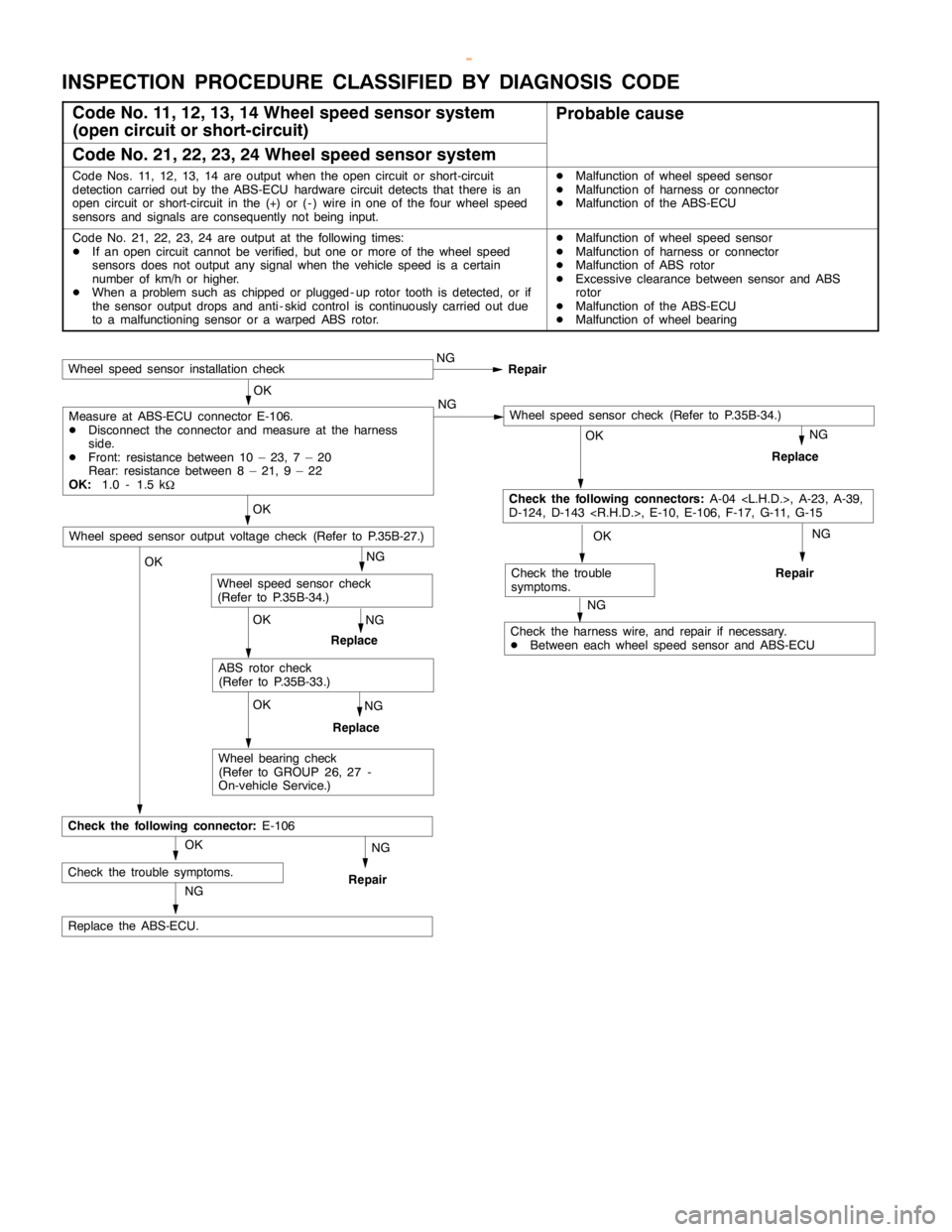
INSPECTION PROCEDURE CLASSIFIED BY DIAGNOSIS CODE
Code No. 11, 12, 13, 14 Wheel speed sensor system
(open circuit or short-circuit)Probable cause
Code No. 21, 22, 23, 24 Wheel speed sensor system
Code Nos. 11, 12, 13, 14 are output when theopencircuit or short-circuit
detection carried out by the ABS-ECU hardware circuit detects that there is an
opencircuit or short-circuit in the (+) or ( - ) wire in one of the four wheel speed
sensors and signals are consequently notbeing input.DMalfunction of wheel speed sensor
DMalfunction of harness or connector
DMalfunction of the ABS-ECU
Code No. 21, 22, 23, 24 are output at the following times:
DIf an opencircuit cannot be verified, but one or more of the wheel speed
sensors does not output any signal when the vehicle speed is a certain
number of km/h or higher.
DWhen a problem such as chipped orplugged - uprotor tooth is detected, or if
the sensor output drops and anti - skid control is continuously carried out due
to a malfunctioning sensor or a warped ABS rotor.DMalfunction of wheel speed sensor
DMalfunction of harness or connector
DMalfunction of ABS rotor
DExcessive clearancebetween sensor and ABS
rotor
DMalfunction of the ABS-ECU
DMalfunction of wheel bearing
NG
NG
Replace the ABS-ECU.
NG
Repair
OK
Check the trouble symptoms.
OK
Check the following connector:E-106
OK
Wheel bearing check
(Refer to GROUP 26, 27 -
On-vehicle Service.)
NG
Replace
OK
ABS rotor check
(Refer to P.35B-33.)
NG
Replace
Wheel speed sensor check
(Refer to P.35B-34.)
OK
Wheel speed sensor output voltage check (Refer to P.35B-27.)
OK
Check the following connectors:A-04
D-124, D-143
Wheel speed sensor installation checkNG
Repair
OK
Measure at ABS-ECU connector E-106.
DDisconnect the connector and measure at the harness
side.
DFront: resistance between 10 – 23, 7 – 20
Rear: resistance between 8 – 21, 9 – 22
OK:1.0 - 1.5 k
WNG
NG
Replace
NG
Repair
OK
Check the trouble
symptoms.
NG
Check the harness wire, and repair if necessary.
DBetween each wheel speed sensor and ABS-ECU
Wheel speed sensor check (Refer to P.35B-34.)
www.WorkshopManuals.co.uk
Purchased from www.WorkshopManuals.co.uk
Page 1272 of 1839
ABS <4WD> -Troubleshooting35B-9
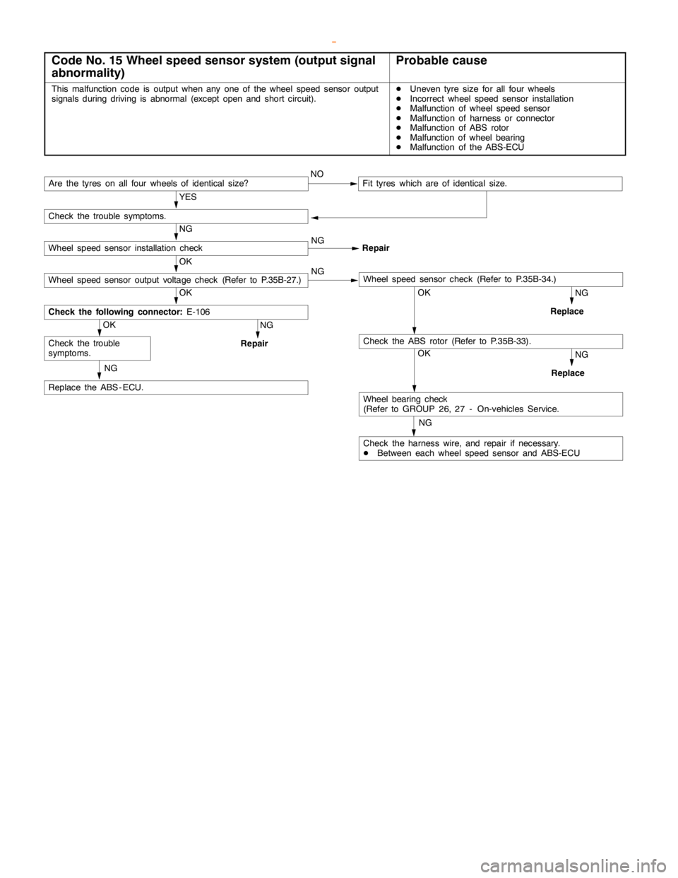
Code No. 15 Wheel speed sensor system (output signal
abnormality)Probable cause
This malfunction code is output when any one of the wheel speed sensor output
signals during driving is abnormal (exceptopen andshort circuit).DUneven tyre size for all four wheels
DIncorrect wheel speed sensor installation
DMalfunction of wheel speed sensor
DMalfunction of harness or connector
DMalfunction of ABS rotor
DMalfunction of wheel bearing
DMalfunction of the ABS-ECU
NG
Check the harness wire, and repair if necessary.
DBetween each wheel speed sensor and ABS-ECU
OK
Wheel bearing check
(Refer to GROUP 26, 27 - On-vehicles Service.
NG
Replace
OKNG
Replace
NG
Replace the ABS - ECU.
OK
Check the trouble
symptoms.
NG
Repair
OK
Check the following connector:E-106
OK
Wheel speed sensor output voltage check (Refer to P.35B-27.)NGWheel speed sensor check (Refer to P.35B-34.)
NG
Wheel speed sensor installation checkNG
Repair
Are the tyres on all four wheels of identical size?NOFit tyres which are of identical size.
YES
Check the trouble symptoms.
Check the ABS rotor (Refer to P.35B-33).
www.WorkshopManuals.co.uk
Purchased from www.WorkshopManuals.co.uk
Page 1277 of 1839
ABS <4WD> -Troubleshooting35B-14
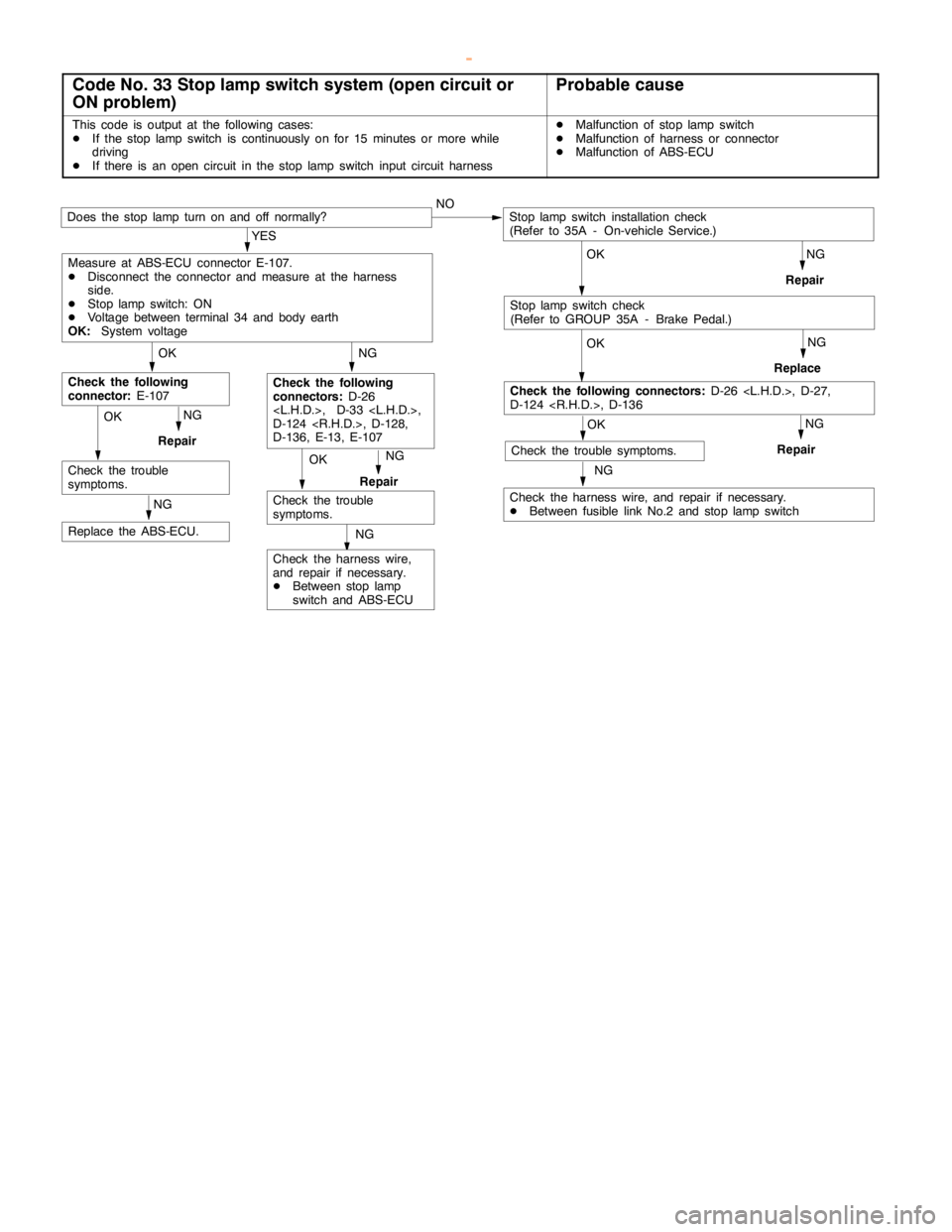
Code No. 33 Stop lamp switch system (open circuit or
ON problem)Probable cause
This code is output at the following cases:
DIf the stoplampswitch is continuously on for 15 minutes or more while
driving
DIf there is an opencircuit in the stoplampswitch input circuit harnessDMalfunction of stoplampswitch
DMalfunction of harness or connector
DMalfunction of ABS-ECU
OK
NG
Check the harness wire,
and repair if necessary.
DBetween stoplamp
switch and ABS-ECU
NG
Replace the ABS-ECU.
NG
Repair
Check the trouble
symptoms.NG
Repair
OK
Check the trouble
symptoms.
NG
Check the following
connectors:D-26
D-124
D-136, E-13, E-107
OK
Check the following
connector:E-107
NG
Check the harness wire, and repair if necessary.
DBetween fusible link No.2 and stoplampswitch
OK
OK
Check the following connectors:D-26
D-124
OK
Does the stoplampturn on and off normally?NO
NG
Repair
NG
Replace
NG
Repair
YES
Measure at ABS-ECU connector E-107.
DDisconnect the connector and measure at the harness
side.
DStoplampswitch: ON
DVoltage between terminal 34 and body earth
OK:System voltage
Stoplampswitch installation check
(Refer to 35A - On-vehicle Service.)
Check the trouble symptoms.
Stoplampswitch check
(Refer to GROUP 35A - Brake Pedal.)
OK
www.WorkshopManuals.co.uk
Purchased from www.WorkshopManuals.co.uk
Page 1283 of 1839
ABS <4WD> -Troubleshooting35B-20
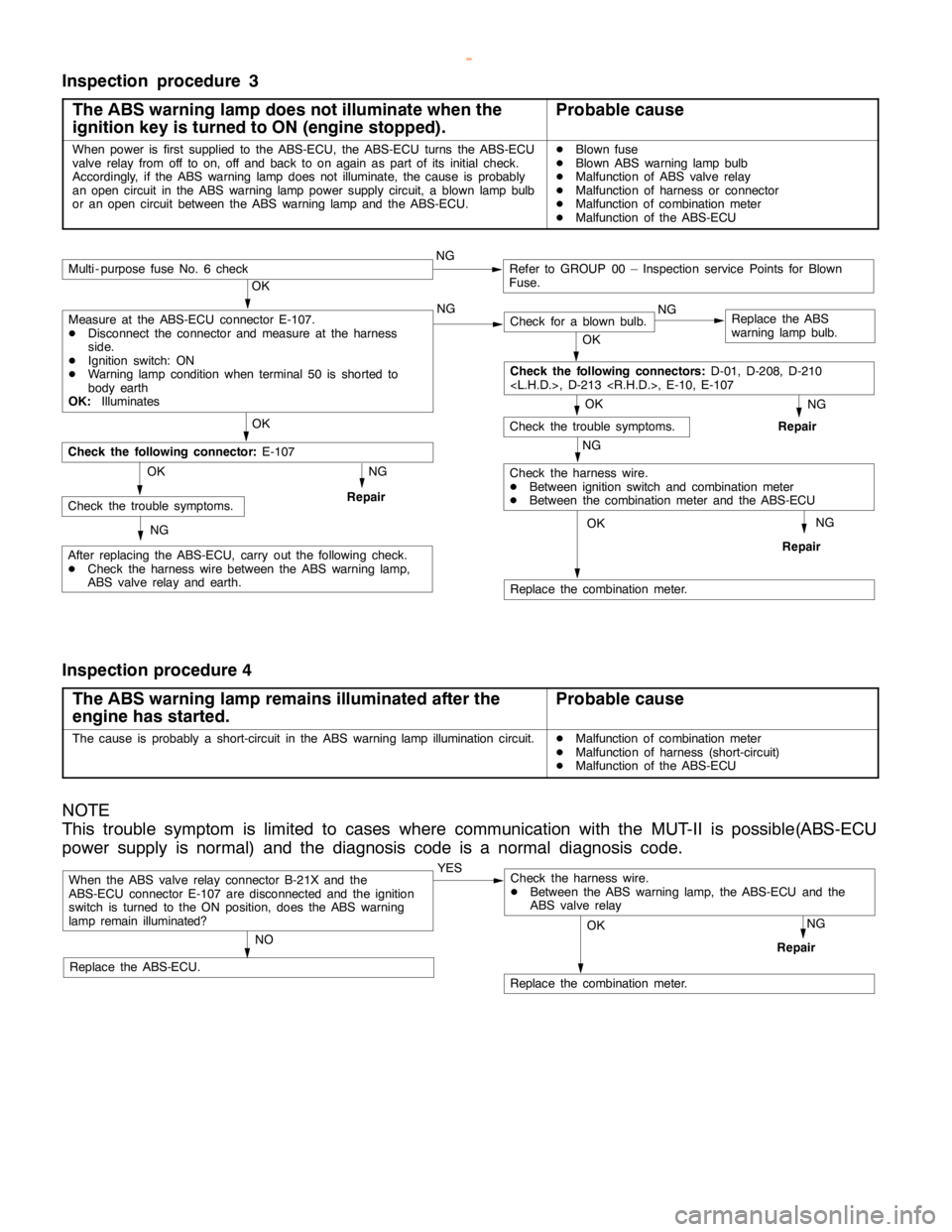
Inspection procedure 3
The ABS warning lamp does not illuminate when the
ignition key is turned to ON (engine stopped).
Probable cause
When power is first supplied to the ABS-ECU, the ABS-ECU turns the ABS-ECU
valve relay from off to on, off and back to onagain aspart of its initial check.
Accordingly, if the ABS warninglampdoes not illuminate, the cause is probably
an opencircuit in the ABS warninglamppower supply circuit, a blownlamp bulb
or an opencircuit between the ABS warninglamp and theABS-ECU.DBlown fuse
DBlown ABS warninglamp bulb
DMalfunction of ABS valve relay
DMalfunction of harness or connector
DMalfunction of combination meter
DMalfunction of the ABS-ECU
NG
Replace the combination meter.
NG
Repair
OK
NG
Check for a blown bulb.Replace the ABS
warning lamp bulb.
OK
NG
Repair
OK
Check the trouble symptoms.
Multi - purpose fuse No. 6 checkNGRefer to GROUP 00 – Inspection service Points for Blown
Fuse.
NG
Check the harness wire.
DBetween ignition switch and combination meter
DBetween the combination meter and the ABS-ECU
OK
OK
After replacing the ABS-ECU, carry out the following check.
DCheck the harness wire between the ABS warning lamp,
ABS valve relay and earth.
Check the following connector:E-107
NG
RepairCheck the trouble symptoms.OK
NG
Check the following connectors:D-01, D-208, D-210
Measure at the ABS-ECU connector E-107.
DDisconnect the connector and measure at the harness
side.
DIgnition switch: ON
DWarning lamp conditionwhen terminal 50 is shorted to
body earth
OK:Illuminates
Inspection procedure 4
The ABS warning lamp remains illuminated after the
engine has started.
Probable cause
The cause is probably a short-circuit in the ABS warninglamp illuminationcircuit.DMalfunction of combination meter
DMalfunction of harness (short-circuit)
DMalfunction of the ABS-ECU
NOTE
This trouble symptom is limited to cases where communication with the MUT-II is possible(ABS-ECU
power supply is normal) and the diagnosis code is a normal diagnosis code.
When the ABS valve relay connector B-21X and the
ABS-ECU connector E-107 are disconnected and the ignition
switch is turned to the ON position, does the ABS warning
lamp remain illuminated?YES
NO
Replace the ABS-ECU.
Replace the combination meter.
NG
Repair
OK
Check the harness wire.
DBetween the ABS warning lamp, the ABS-ECU and the
ABS valve relay
www.WorkshopManuals.co.uk
Purchased from www.WorkshopManuals.co.uk
Page 1284 of 1839
ABS <4WD> -Troubleshooting35B-21
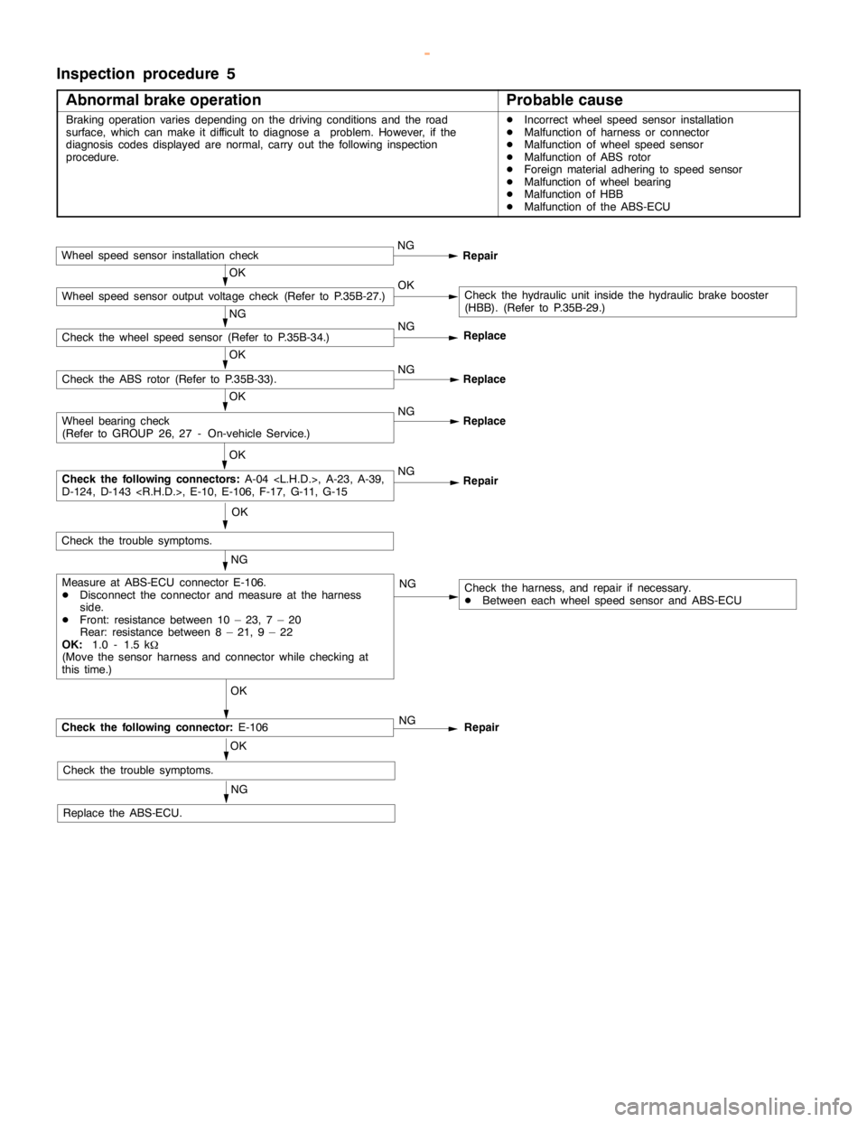
Inspection procedure 5
Abnormal brake operation
Probable cause
Braking operation variesdepending on the driving conditions and the road
surface, which can make it difficult to diagnose a problem. However, if the
diagnosis codes displayed are normal, carry out the following inspection
procedure.DIncorrect wheel speed sensor installation
DMalfunction of harness or connector
DMalfunction of wheel speed sensor
DMalfunction of ABS rotor
DForeign material adhering to speed sensor
DMalfunction of wheel bearing
DMalfunction of HBB
DMalfunction of the ABS-ECU
Wheel speed sensor installation checkNG
Repair
OKCheck the hydraulic unit inside the hydraulic brake booster
(HBB). (Refer to P.35B-29.)
NG
Check the wheel speed sensor (Refer to P.35B-34.)NG
OK
Check the ABS rotor (Refer to P.35B-33).NG
Replace
OK
NG
Replace
OK
NG
Repair
OK
NG
NG
OK
Check the following connector:E-106
OK
Check the trouble symptoms.
NG
Replace the ABS-ECU.NG
Repair
Check the harness, and repair if necessary.
DBetween each wheel speed sensor and ABS-ECU ReplaceMeasure at ABS-ECU connector E-106.
DDisconnect the connector and measure at the harness
side.
DFront: resistance between 10 – 23, 7 – 20
Rear: resistance between 8 – 21, 9 – 22
OK:1.0 - 1.5 k
W
(Move the sensor harness and connector while checking at
this time.)
Check the following connectors:A-04
D-124, D-143
Wheel bearing check
(Refer to GROUP 26, 27 - On-vehicle Service.)
Check the trouble symptoms.
Wheel speed sensor output voltage check (Refer to P.35B-27.)OK
www.WorkshopManuals.co.uk
Purchased from www.WorkshopManuals.co.uk