2000 MITSUBISHI MONTERO MOTOR
[x] Cancel search: MOTORPage 1220 of 1839

BASIC BRAKE SYSTEM -Troubleshooting35A-12
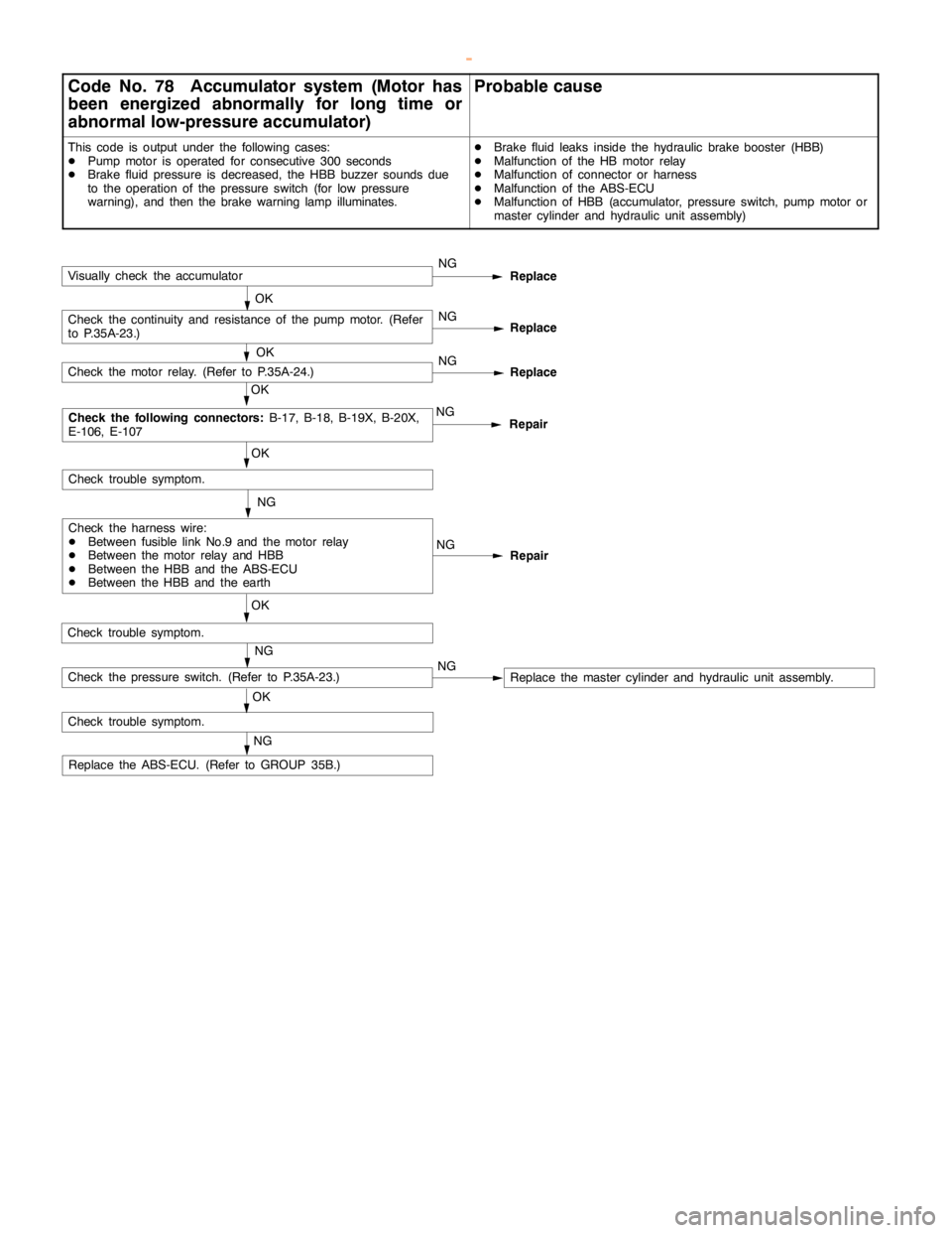
Code No. 78 Accumulator system (Motor has
been energized abnormally for long time or
abnormal low-pressure accumulator)Probable cause
This code is output under the following cases:
DPump motor is operated for consecutive 300 seconds
DBrake fluid pressure is decreased, the HBB buzzer sounds due
to the operation of the pressure switch (for low pressure
warning), and then the brake warninglamp illuminates.DBrake fluid leaks inside the hydraulic brake booster (HBB)
DMalfunction of the HB motor relay
DMalfunction of connector or harness
DMalfunction of the ABS-ECU
DMalfunction of HBB (accumulator, pressure switch,pump motor or
master cylinder and hydraulic unit assembly)
NG
Repair
NG
OK
Check trouble symptom.
Repair NGNG
OK
Check trouble symptom.
Replace
OK
Check the following connectors:
B-17, B-18, B-19X, B-20X,
E-106, E-107
Check the harness wire:
DBetween fusible link No.9 and the motor relay
DBetween the motor relay and HBB
DBetween the HBB and the ABS-ECU
DBetween the HBB and the earthNG
Check the motor relay. (Refer to P.35A-24.)
NG
Replace the ABS-ECU. (Refer to GROUP 35B.)
Check trouble symptom.
NG
OKCheck the pressure switch. (Refer to P.35A-23.)NG
Replace
OKCheck the continuity and resistance of thepump motor.(Refer
to P.35A-23.)NG
Replace
OKVisually check the accumulator
Replace the master cylinder and hydraulic unit assembly.
www.WorkshopManuals.co.uk
Purchased from www.WorkshopManuals.co.uk
Page 1224 of 1839

BASIC BRAKE SYSTEM -Troubleshooting35A-16
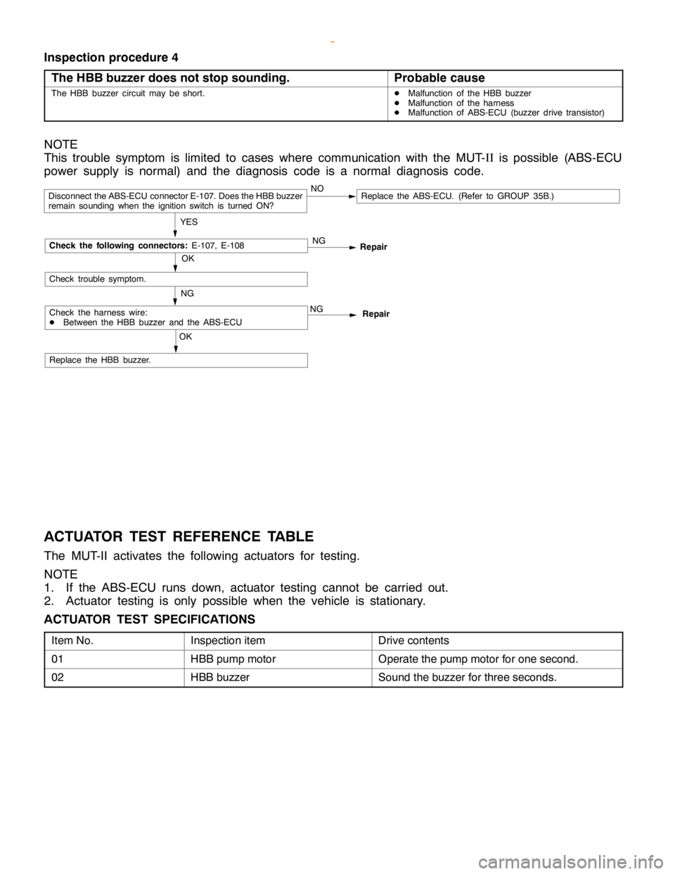
Inspection procedure 4
The HBB buzzer does not stop sounding.
Probable cause
The HBB buzzer circuit may be short.DMalfunction of the HBB buzzer
DMalfunction of the harness
DMalfunction of ABS-ECU (buzzer drive transistor)
NOTE
This trouble symptom is limited to cases where communication with the MUT-II
is possible (ABS-ECU
power supply is normal) and the diagnosis code is a normal diagnosis code.
OK
Repair NG
Repair
Replace the HBB buzzer.
OK
NG
YES
Replace the ABS-ECU. (Refer to GROUP 35B.)NODisconnect the ABS-ECU connector E-107. Does the HBB buzzer
remain sounding when the ignition switch is turned ON?
Check trouble symptom.
Check the harness wire:
DBetween the HBB buzzer and the ABS-ECUNG
Check the following connectors:
E-107, E-108
ACTUATOR TEST REFERENCE TABLE
The MUT-II activates the following actuators for testing.
NOTE
1. If the ABS-ECU runs down, actuator testing cannot be carried out.
2. Actuator testing is only possible when the vehicle is stationary.
ACTUATOR TEST SPECIFICATIONS
Item No.Inspection itemDrive contents
01HBB pump motorOperate the pump motor for one second.
02HBB buzzerSound the buzzer for three seconds.
www.WorkshopManuals.co.uk
Purchased from www.WorkshopManuals.co.uk
Page 1235 of 1839

BASIC BRAKE SYSTEM -On-vehicle ServiceBASIC BRAKE SYSTEM -On-vehicle Service35A-27
BLEEDING
Caution
Specified brake fluid: DOT3 or DOT4
1. Always use the specified brake fluid. Avoid using
a mixture of the specified brake fluid and other fluid.
2. Maintain the fluid reservoir level between the MIN
and MAX marks during the air bleeding.
3. Do not depress the brake pedal hard during the air
bleeding (normal air bleeding) to prevent the pump
motor from operating frequently.
4. After the air bleeding, check that the brake dragging
does not become stronger.
5. If the pedal is depressed with the reservoir cap
removed, the brake fluid may overflow. Do not depress
the brake pedal while the fluid is being added.
NORMAL AIR BLEEDING
After the front brake or the rear brake is removed and installed,
some fluid may remain in the hydraulic brake booster (HBB)
reservoir. In this case, bleed air from the brake caliper.
HBB SYSTEM AIR BLEEDING
If all the brake fluid inside the reservoir is drained due to
the removal and installation of the HBB, bleed air as follows:
Air bleeding from front brake system
1. Turn the ignition switch to the LOCK (OFF) position. Bleed
air from the front brake calipers (right and left) by pumping
the brake pedal.
Pump motor operation
2. Turn the ignition switch ON, and operate the pump motor.
If the pump motor is running free, supply the brake fluid
into the pump motor by depressing the brake pedal three
or four times.
Air bleeding from accumulator system
3. After the pump motor stopped, depress the brake pedal
three or four times with the ignition switch ON. Then
observe the brake fluid in the reservoir. If the brake fluid
looks whitish, wait for a few minutes until it becomes
clear.
4. Repeat step 3 until the brake fluid becomes clear.
www.WorkshopManuals.co.uk
Purchased from www.WorkshopManuals.co.uk
Page 1264 of 1839

35B-1
ANTI-SKID
BRAKING SYSTEM
(ABS) <4WD>
CONTENTS
GENERAL INFORMATION 2..................
SERVICE SPECIFICATIONS 4.................
LUBRICANT Refer to GROUP 35A...........
SEALANTS Refer to GROUP 35A............
SPECIAL TOOLS 4..........................
TROUBLESHOOTING 4.......................
ON-VEHICLE SERVICE 27...................
Wheel Speed Sensor Output Voltage
Measurement 27...............................
ABS Valve Relay Continuity Check 28...........
Hydraulic Brake Booster (HBB) - Hydraulic Unit
Check 29......................................
Solenoid Valve Check 30.......................
When the Battery is Flat 31....................
Brake Pedal Check and Adjustment
Refer to GROUP 35A ..........................
Hydraulic Brake Booster (HBB) Operation Check
Refer to GROUP 35A ..........................
Hydraulic Brake Booster (HBB) Check
Refer to GROUP 35A ..........................Motor Relay Continuity Check
Refer to GROUP 35A ..........................
Bleeding Refer to GROUP 35A..................
Brake Fluid Level Sensor Check
Refer to GROUP 35A ..........................
Disc Brake Pad Check and Replacement
Refer to GROUP 35A ..........................
Brake Disc Thickness Check
Refer to GROUP 35A ..........................
Brake Disc Runout Check and Correction
Refer to GROUP 35A ..........................BRAKE PEDAL Refer to GROUP 35A........
HYDRAULIC BRAKE BOOSTER (HBB)
Refer to GROUP 35A ........................
HBB BUZZER Refer to GROUP 35A..........
FRONT DISC BRAKE Refer to GROUP 35A..
REAR DISC BRAKE Refer to GROUP 35A....
ABS-ECU 32................................
WHEEL SPEED SENSOR 33.................
G-SENSOR 36..............................
www.WorkshopManuals.co.uk
Purchased from www.WorkshopManuals.co.uk
Page 1353 of 1839

42-1
BODY
CONTENTS
HOOD3 ....................................
FENDER5 ..................................
FUEL FILLER DOOR6 .....................
WINDOW GLASS8 .........................
ADHESIVES 8.............................
SPECIAL TOOL 8.........................
WINDOW REPAIR 8.......................
WINDSHIELD 10..........................
QUARTER WINDOW GLASS 14...........
BACK DOOR GLASS 16..................
DOORS18 .................................
SERVICE SPECIFICATIONS 18............
SEALANT 18.............................
SPECIAL TOOLS 18......................
TROUBLESHOOTING 19..................ON-VEHICLE SERVICE 19................
Door Fit Adjustment 19.................
Door Window Glass Adjustment 19......
Defective Power Window Adjustment and
Replacement
20 .........................
Power Window Safety Mechanism Check 20..
Door Outside Handle Play Check 21.....
Power Window Operation Current
Check 21..............................
Circuit Breaker (Incorporated in the Power
Window Motor) Check 21...............
Door Inside Handle Play Check and
Adjustment 21..........................
DOOR ASSEMBLY 22.....................
DOOR TRIM AND WATERPROOF
FILM 24..................................
DOOR GLASS AND REGULATOR 30......
DOOR HANDLE AND LATCH 33..........
WINDOW GLASS RUNCHANNEL AND
DOOR OPENING WEATHERSTRIP 36.....
BACK DOOR39 ...........................
SERVICE SPECIFICATION 39.............
SEALANT 39.............................
SPECIAL TOOL 39.......................
TROUBLESHOOTING 39..................
CONTINUED ON NEXT PAGE
www.WorkshopManuals.co.uk
Purchased from www.WorkshopManuals.co.uk
Page 1402 of 1839

BODY -SunroofBODY -Sunroof42-50
"
BA
SUNROOF MOTOR ASSEMBLY INSTALLATION
1. Install the roof lid glass assembly and the sunroof motor
assembly with the sunroof motor assembly in the
fully-closed position.
2. Connect the sunroof motor assembly harness connector
and the sunroof switch harness connector to the vehicle
wiring harness connector.
3. Operate the sunroof and check that it operates correctly.
1. Install the roof lid glass assembly and the sunroof motor
assembly with the sunroof motor assembly in the
fully-closed position.
2. Connect the sunroof motor assembly harness connector
and the sunroof switch harness connector to the vehicle
wiring harness connector.
3. Operate the sunroof switch to slide the roof lid glass
to the fully-open position, and then tilt it up in steps of
30 mm to the fully-open position and then keep pressing
the switch for 3 seconds or more.
4. Operate the sunroof switch (CLOSE) using the one-touch
function to slide the roof lid glass to the fully-closed
position.
5. Operate the sunroof switch (OPEN) using the one-touch
function to slide the roof lid glass to the fully-open position.
6. Operate the sunroof switch (CLOSE) using the one-touch
function to slide the roof lid glass to the fully-closed
position.
7. Press the tilt - up switch to operate the sunroof and check
that learning is complete.
NOTE
(1) During initialisation (learning mode), use only the
CLOSE/DOWN switch to move the roof lid glass from
the fully-closed position to the fully tilted open position.
During initialisation, the TILT UP switch will not work
when pressed. Furthermore, the sunroof-ECU will stop
running in learning mode as soon as the roof lid glass
is tilted up.
(2) When the clamping prevention mechanism is
cancelled, the operation is the same as when the
roof lid glass operates 30 mm at a time.
www.WorkshopManuals.co.uk
Purchased from www.WorkshopManuals.co.uk
Page 1573 of 1839

54A-3
ON-VEHICLE SERVICE 46......................
Room Lamp Delay-off Time Adjustment
Procedure 46...............................
REAR COMBINATION LAMP 47...........
SPECIAL TOOLS 47...........................
TROUBLESHOOTING 47.......................
REAR COMBINATION LAMP 47................
HIGH-MOUNTED STOP LAMP 48.........
COLUMN SWITCH 48....................
SPECIAL TOOLS 48...........................
COLUMN SWITCH 48..........................
HAZARD WARNING LAMP SWITCH 50....
SPECIAL TOOLS 50...........................
HAZARD WARNING LAMP SWITCH 50.........
HORN 51................................
CIGARETTE LIGHTER 51.................
ACCESSORY SOCKET 51................
RHEOSTAT 52...........................
CLOCK OR CENTER DISPLAY 53........
TROUBLESHOOTING 53.......................
CLOCK OR CENTER DISPLAY 67..............
RADIO/TAPE PLAYER 68.................
TROUBLESHOOTING 68.......................
RADIO AND CD AUTO CHANGER 81..........
FRONT SPEAKERS 82...................
REAR SPEAKERS 82.....................
ANTENNA83 ............................DEFOGGER 86...........................
TROUBLESHOOTING
ON-VEHICLE SERVICE 86.....................
Printed Heater Check 86.....................
Defogger Relay Continuity Check 86...........
DEFOGGER SWITCH 87.......................
SMART WIRING SYSTEM (SWS)
Refer to GROUP 54B ....................
RADIATOR (RADIATOR FAN MOTOR)
Refer to GROUP 14 ......................
AUTOMATIC TRANSMISSION
Refer to GROUP 23 ......................
ANTI-LOCK BRAKE SYSTEM (ABS)
Refer to GROUP 35B ....................
DOOR HANDLE LATCH (DOOR LOCK)
Refer to GROUP 42 ......................
DOOR GLASS-REGULATOR (POWER
WINDOWS)
Refer to GROUP 42 ......................
KEYLESS ENTRY SYSTEM
Refer to GROUP 42 ......................
WINDSHIELD WIPER/WASHER
Refer to GROUP 51 ......................
REAR WIPER/WASHER
Refer to GROUP 51 ......................
SRS AIRBAG Refer to GROUP 52B......
HEATER Refer to GROUP 55.............
AIR CONDITIONER Refer to GROUP 55...
www.WorkshopManuals.co.uk
Purchased from www.WorkshopManuals.co.uk
Page 1688 of 1839

SWS -General InformationSWS -General Information54B-2
GENERAL INFORMATION
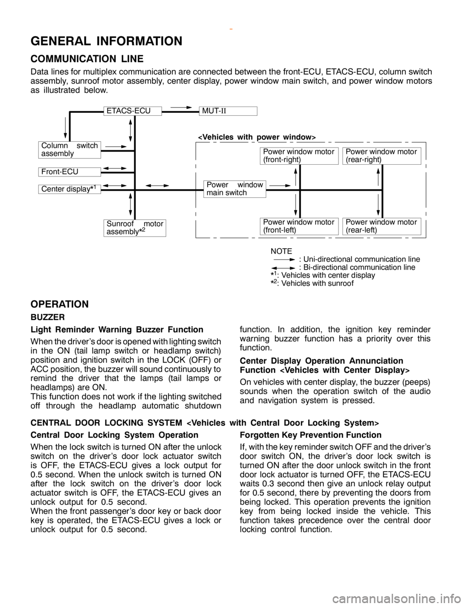
COMMUNICATION LINE
Data lines for multiplex communication are connected between the front-ECU, ETACS-ECU, column switch
assembly, sunroof motor assembly, center display, power window main switch, and power window motors
as illustrated below.
ETACS-ECUMUT-II
Column switch
assembly
Front-ECU
Power window
main switch
Power window motor
(front-right)
Center display*1
Sunroof motor
assembly*2Power window motor
(front-left)
Power window motor
(rear-right)
Power window motor
(rear-left)
NOTE
: Uni-directional communication line
: Bi-directional communication line
*
1: Vehicles with center display
*2: Vehicles with sunroof
OPERATION
BUZZER
Light Reminder Warning Buzzer Function
When the driver’s door is opened with lighting switch
in the ON (tail lamp switch or headlamp switch)
position and ignition switch in the LOCK (OFF) or
ACC position, the buzzer will sound continuously to
remind the driver that the lamps (tail lamps or
headlamps) are ON.
This function does not work if the lighting switched
off through the headlamp automatic shutdownfunction. In addition, the ignition key reminder
warning buzzer function has a priority over this
function.
Center Display Operation Annunciation
Function
On vehicles with center display, the buzzer (peeps)
sounds when the operation switch of the audio
and navigation system is pressed.
CENTRAL DOOR LOCKING SYSTEM
Central Door Locking System Operation
When the lock switch is turned ON after the unlock
switch on the driver’s door lock actuator switch
is OFF, the ETACS-ECU gives a lock output for
0.5 second. When the unlock switch is turned ON
after the lock switch on the driver’s door lock
actuator switch is OFF, the ETACS-ECU gives an
unlock output for 0.5 second.
When the front passenger’s door key or back door
key is operated, the ETACS-ECU gives a lock or
unlock output for 0.5 second.Forgotten Key Prevention Function
If, with the key reminder switch OFF and the driver’s
door switch ON, the driver’s door lock switch is
turned ON after the door unlock switch in the front
door lock actuator is turned OFF, the ETACS-ECU
waits 0.3 second then give an unlock relay output
for 0.5 second, there by preventing the doors from
being locked. This operation prevents the ignition
key from being locked inside the vehicle. This
function takes precedence over the central door
locking control function.
www.WorkshopManuals.co.uk
Purchased from www.WorkshopManuals.co.uk