2000 MITSUBISHI MONTERO MOTOR
[x] Cancel search: MOTORPage 1689 of 1839

SWS -General Information54B-3
POWER WINDOWS
Power Windows Operation
A signal line dedicated for transmission of multiplex
communication data is connected between the
power window main switches and the power window
motor-ECU.
Communication is uni-directional. The power
window main switches have a transmitting circuit
only, whereas the power window sub switches have
a receiving circuit only.
Power Window Timer Function
With the ignition switch in the ON position, the power
window relay and power window switch receipt
permission signal (a SWS signal transmitted from
the ETACS-ECU) are turned ON [the power windowswitch receipt permission signal remains ON for 30
seconds after the ignition switch is turned LOCK
(OFF)], enabling opening and closing of the
windows. The power window relay goes ON for
additional 30 seconds. If the driver’s door is
subsequently closed during this period, the receipt
permission signal goes OFF. The power window
relay goes OFF 10 seconds after the receipt
permission signal goes OFF.
If the driver’s door is opened during timer operation,
the receipt permission signal goes ON for additional
30 seconds. If the driver’s door is subsequently
closed during this period, the receipt permission
signal goes OFF ten seconds after the receipt
permission signal goes OFF.
KEYLESS ENTRY SYSTEM
Keyless Entry System Operation
If the transmitter LOCK or UNLOCK switch is
pressed while the ignition key is removed and all
of the doors are closed, the doors can be locked
or unlocked.
Keyless Entry Answerback Function
The keyless entry hazard answerable function
facilitates confirmation of door locking and unlock-
ing operations even in daylight. When a LOCKsignal from the keyless entry transmitter is applied
to the ETACS-ECU, all of the turn-signal lamps flash
twice. When an UNLOCK signal from the keyless
entry transmitter is applied to the ETACS-ECU, all of
the turn-signal lamps flash four times. Note that an
unlock switch has change from OFF to ON.
NOTE
The hazard answer back is enabled or disabled
by the configuration function.
SUNROOF
Sunroof Operation
All of the slide open/close, tilt up/down, and stop
operations can be performed by a single switch.
When the roof lid glass is tilted up, the sunshade
opens approximately 98 mm in combined operation
with the roof lid glass for better ventilation.
A jam preventing mechanism has been adopted.
When a slide-close or tilt-down operation is blocked
by an external force, the roof lid glass moves back
and stops.Sunroof Timer Function
When the ignition switch is turned from ON position
to LOCK (OFF) or ACC position, the sunroof will
be ready to work for 30 seconds.
If the driver’s door is opened during the timer
operation, the timer operates for another
30
seconds starting from that point. However, the
timer operation discontinues if the door is closed
during that period.
www.WorkshopManuals.co.uk
Purchased from www.WorkshopManuals.co.uk
Page 1694 of 1839

SWS -Troubleshooting54B-8
TROUBLESHOOTING
STANDARD FLOW OF DIAGNOSTIC TROUBLESHOOTING
Refer to GROUP 00 – How to Use Troubleshooting/Inspection Service Points.
DIAGNOSTIC FUNCTION
DIAGNOSIS CODES CHECK
Use the MUT-II
to check a diagnosis code.
(Refer to GROUP 00 – How to Use Troubleshooting/Inspection Service Points.)
NOTE
Connect the MUT-II
to the 16-pin diagnosis connector (black).
INPUT SIGNAL CHECK
1. Use the MUT-II
to check a input signal.
(Refer to GROUP 00 – How to Use Troubleshooting/Inspection Service Points.)
2. In this condition, the following input switches can be checked.
3. If an abnormality is found during the input signal check, carry out troubleshooting while referring
to the Trouble Symptom Check page.
Input Signal Check Function
Input signalBuzzer operation condition
Ignition switch (ACC)Turned from LOCK(OFF) to ACC
Ignition switch (IG1)Turned from ACC to ON
Key reminder switch
(from inserted position)
Hazard warning lamp switchTurned from OFF to ON
Front fog lamp switch
Rear fog lamp switch
Back-up lamp switch
Inhibitor switch (reverse)
washer>Selector lever moved to R position
Rear wiper motor auto-stop signal
is sent before the rear wiper begins to operate)
Driver’s door switchDriver’s door opened from closed condition
Door switchesAll doors closed to any door opened
Front passenger’s or back door lock key cylinder switch
Driver’s door lock actuator switch
position to unlock position or vice versa
www.WorkshopManuals.co.uk
Purchased from www.WorkshopManuals.co.uk
Page 1698 of 1839
SWS -Troubleshooting54B-12
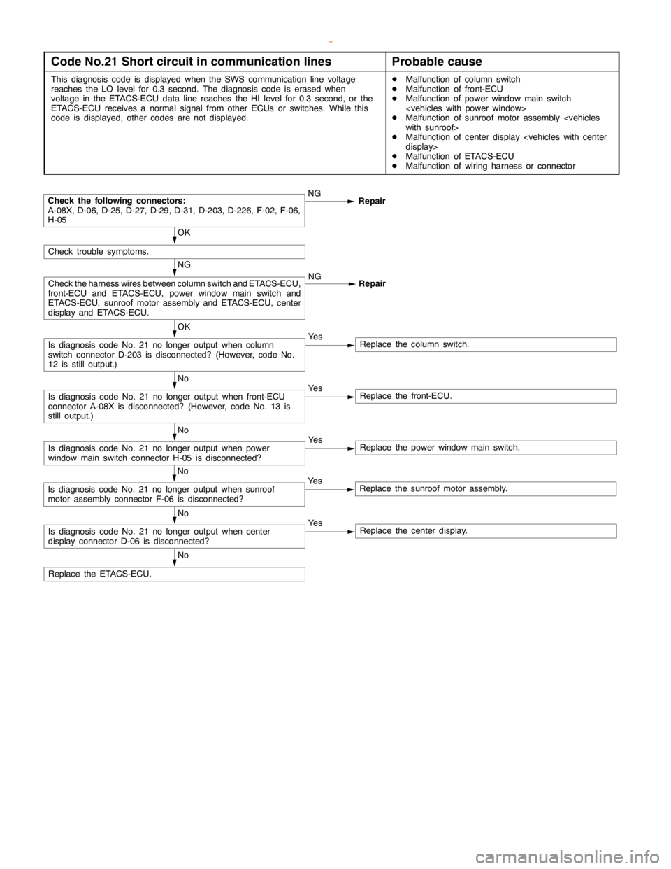
Code No.21 Short circuit in communication linesProbable cause
This diagnosis code is displayed when the SWS communication line voltage
reaches the LO level for 0.3 second. The diagnosis code is erased when
voltage in the ETACS-ECU data line reaches the HI level for 0.3 second, or the
ETACS-ECU receives a normal signal from other ECUs or switches. While this
code is displayed, other codes are not displayed.DMalfunction of column switch
DMalfunction of front-ECU
DMalfunction of power windowmainswitch
DMalfunction of sunroof motor assembly
DMalfunction of center display
DMalfunction of ETACS-ECU
DMalfunction of wiring harness or connector
NG
Repair
OK
Ye s
Replace the column switch.
No
Ye s
Replace the front-ECU.
No
Ye s
Replace the power windowmainswitch.
No
Ye s
Replace the center display.
No
Replace the ETACS-ECU.
No
Ye s
Replace the sunroof motor assembly.
Is diagnosis code No. 21 no longer output when center
display connector D-06 is disconnected?
Is diagnosis code No. 21 no longer output when sunroof
motor assembly connector F-06 is disconnected?
Is diagnosis code No. 21 no longer output when power
window mainswitch connector H-05 is disconnected?
Is diagnosis code No. 21 no longer output when front-ECU
connector A-08X is disconnected? (However, code No. 13 is
still output.)
Is diagnosis code No. 21 no longer output when column
switch connector D-203 is disconnected? (However, code No.
12 is still output.)
NG
Check the harness wires between column switch and ETACS-ECU,
front-ECU and ETACS-ECU, power windowmainswitch and
ETACS-ECU, sunroof motor assembly and ETACS-ECU, center
display and ETACS-ECU.NG
Repair
OK
Check trouble symptoms.
Check the following connectors:
A-08X, D-06, D-25, D-27, D-29, D-31, D-203, D-226, F-02, F-06,
H-05
www.WorkshopManuals.co.uk
Purchased from www.WorkshopManuals.co.uk
Page 1701 of 1839

SWS -Troubleshooting54B-15
Trouble symptomInspection
procedureReference
page
Rear fog lampRear fog lamp do not illuminate when the rear fog lamp switch
is turned on.N-154B-40
Rear fog lamp do not go out when the headlamps and front fog
lamps are turned off while the rear fog lamp is on.N-254B-40
Room lampRoom lamp does not illuminate.O-154B-41
Room lamp dimming function does not work normally.O-254B-41
Center displayCenter display does not work normally.–GROUP 54A
– Center Dis-
play.
DEFECTS FOUND BY INPUT SIGNAL CHECK
If the input signal check finds a defect, follow the table below to check.
Trouble symptomInspection
procedureReference
page
Ignition switch (ACC) signal is not sent to the ETACS-ECU.P-154B-42
Ignition switch (IG1) signal is not sent to the ETACS-ECU.P-254B-42
Key reminder switch signal is not sent to the ETACS-ECU.P-354B-43
Hazard warning lamp switch signal is not sent to the ETACS-ECU.P-454B-43
Front fog lamp switch signal is not sent to the ETACS-ECU.P-554B-44
Rear fog lamp switch signal is not sent to the ETACS-ECU.P-654B-45
Back-up lamp switch signal is not sent to the ETACS-ECU.
Inhibitor switch (reverse) signal is not sent to the ETACS-ECU.P-854B-46
Rear wiper motor auto-stop signal is not sent to the ETACS-ECU.P-954B-46
Driver’s door switch signal is not sent to the ETACS-ECU.P-1054B-47
Door switches signal is not sent to the ETACS-ECU.
Front passenger’s or back door lock key cylinder switch signal is not sent to the
ETACS-ECU.P-1154B-48
Driver’s door lock actuator switch signal is not sent to the ETACS-ECU.P-1254B-48
www.WorkshopManuals.co.uk
Purchased from www.WorkshopManuals.co.uk
Page 1707 of 1839
SWS -Troubleshooting54B-21
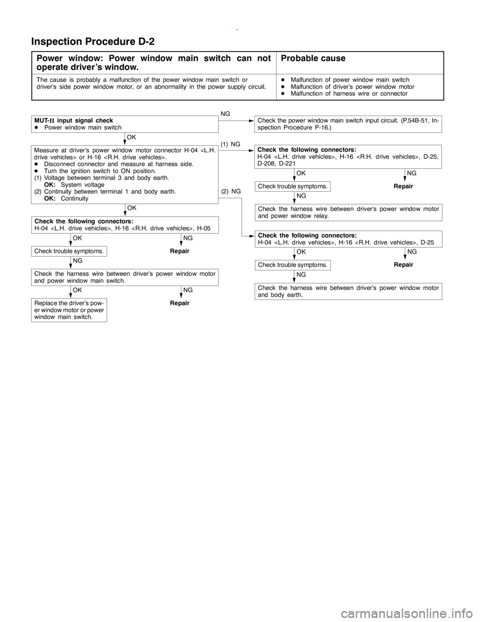
Inspection Procedure D-2
Power window: Power window main switch can not
operate driver’s window.Probable cause
The cause is probably a malfunction of the power windowmainswitch or
driver’s side power window motor, or an abnormality in the power supply circuit.DMalfunction of power windowmainswitch
DMalfunction of driver’s power window motor
DMalfunction of harness wire or connector
NG
Repair
NG
Check the harness wire between driver’s power window motor
and power window relay.
NG
Repair
NG
Check the harness wire between driver’s power window motor
and body earth.
NG
OK
Check trouble symptoms. NG
Repair
OK
Replace the driver’s pow-
er window motor or power
window mainswitch.
NG
Repair
NG
Check the harness wire between driver’s power window motor
and power windowmainswitch.
OK
Check trouble symptoms.
OK
Check the following connectors:
H-04
(2) NG
Check the following connectors:
H-04
OK
Check trouble symptoms.
OK
Measure at driver’s power window motor connector H-04
DDisconnect connector and measure at harness side.
DTurn the ignition switch to ON position.
(1) Voltage between terminal 3 and body earth.
OK:System voltage
(2) Continuity between terminal 1 and body earth.
OK:Continuity(1) NGCheck the following connectors:
H-04
D-208, D-221
MUT-
IIinput signal check
DPower windowmainswitchCheck the power windowmainswitch input circuit. (P.54B-51, In-
spection Procedure P-16.)
www.WorkshopManuals.co.uk
Purchased from www.WorkshopManuals.co.uk
Page 1708 of 1839
SWS -Troubleshooting54B-22
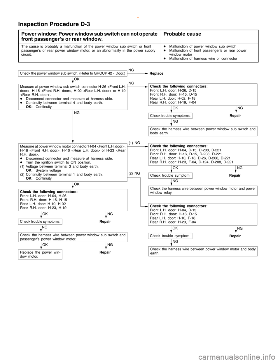
Inspection Procedure D-3
Power window: Power window sub switch can not operate
front passenger’s or rear window.Probable cause
The cause is probably a malfunction of the power window sub switch or front
passenger’s or rear power window motor, or an abnormality in the power supply
circuit.DMalfunction of power window sub switch
DMalfunction of front passenger’s or rear power
window motor
DMalfunction of harness wire or connector
NG
Repair
OK
NG
Check the harness wire between power window sub switch and
body earth.
NG
Repair
NG
Repair
NG
Repair
NG
Check the harness wire between power window motor and body
earth.
NG
Check the harness wire between power window motor and power
window relay.
OK
Replace the power win-
dow motor.
NG
Repair
NG
Check the harness wire between power window sub switch and
passenger’s power window motor.
OK
Check trouble symptoms.
Check the following connectors:
Front L.H. door: H-04, H-26
Front R.H. door: H-16, H-15
Rear L.H. door: H-10, H-02
Rear R.H. door: H-23, H-19
OK
Check trouble symptom
(2) NG
Check the following connectors:
Front L.H. door: H-04, D-15
Front R.H. door: H-16, D-15
Rear L.H. door: H-10, F-18
Rear R.H. door: H-23, F-04
OK
Check trouble symptom
NG
(1) NG
Check the following connectors:
Front L.H. door: H-04, D-15, D-208, D-221
Front R.H. door: H-16, D-15, D-208, D-221
Rear L.H. door: H-10, F-18, D-26, D-208, D-221
Rear R.H. door: H-23, F-04, D-124, D-208, D-221Measure at power window motor connector H-04
H-16
DDisconnect connector and measure at harness side.
DTurn the ignition switch to ON position.
(1) Voltage between terminal 3 and body earth.
OK:System voltage
(2) Continuity between terminal 1 and body earth.
OK:Continuity
OK
Check trouble symptoms.
OK
Measure at power window sub switch connector H-26
DDisconnect connector and measure at harness side.
DContinuity between terminal 4 and body earth.
OK:ContinuityNGCheck the following connectors:
Front L.H. door: H-26, D-15
Front R.H. door: H-15, D-15
Rear L.H. door: H-02, F-18
Rear R.H. door: H-19, F-04
Check the power window sub switch. (Refer to GROUP 42 - Door.)NG
Replace
www.WorkshopManuals.co.uk
Purchased from www.WorkshopManuals.co.uk
Page 1709 of 1839
SWS -Troubleshooting54B-23
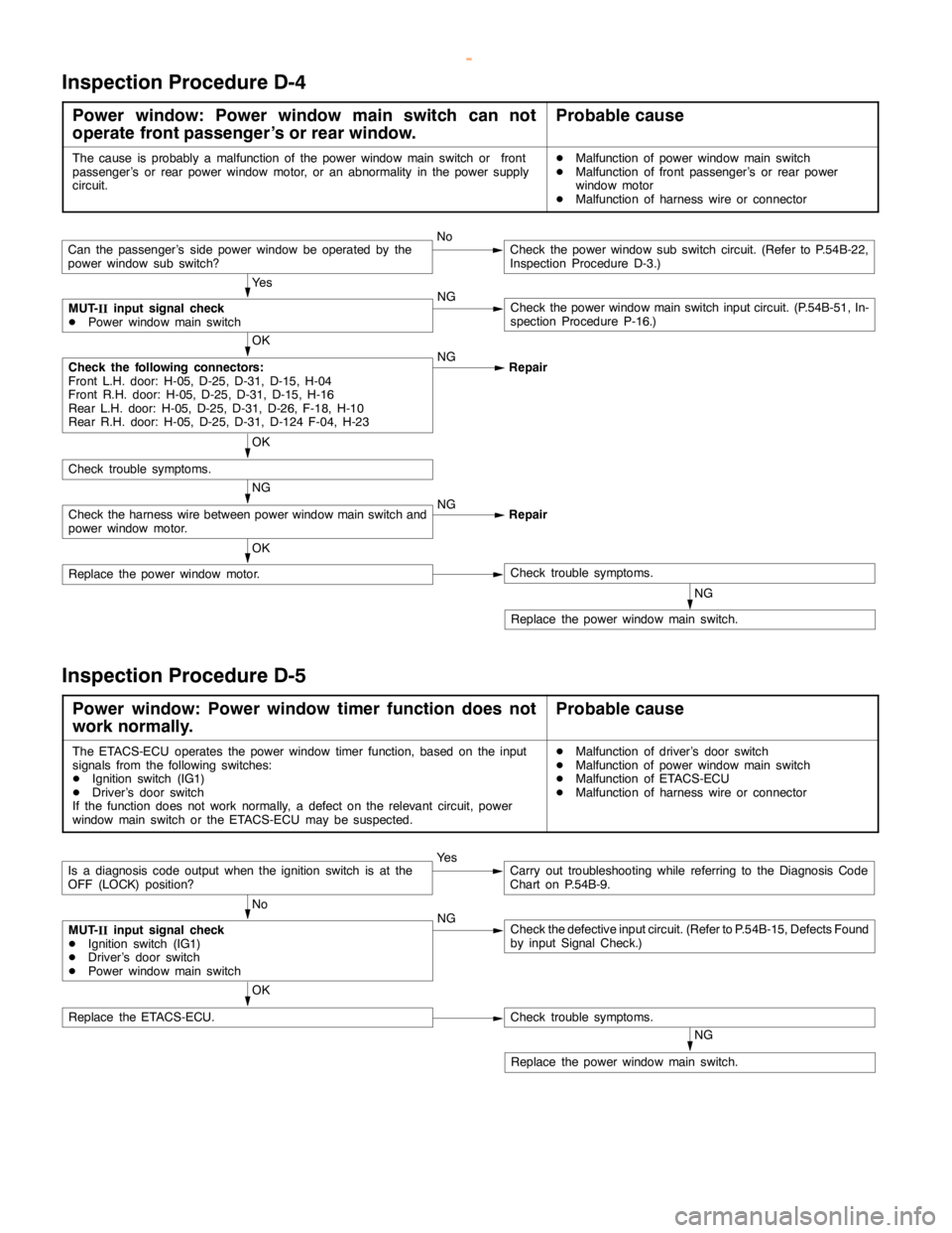
Inspection Procedure D-4
Power window: Power window main switch can not
operate front passenger’s or rear window.Probable cause
The cause is probably a malfunction of the power windowmainswitch or front
passenger’s or rear power window motor, or an abnormality in the power supply
circuit.DMalfunction of power windowmainswitch
DMalfunction of front passenger’s or rear power
window motor
DMalfunction of harness wire or connector
NG
Replace the power windowmainswitch.
OK
Replace the power window motor.Check trouble symptoms.
NG
Check the harness wire between power windowmainswitch and
power window motor.NG
Repair
OK
Check trouble symptoms.
Ye s
NG
Check the power windowmainswitch input circuit. (P.54B-51, In-
spection Procedure P-16.)
OK
Check the following connectors:
Front L.H. door: H-05, D-25, D-31, D-15, H-04
Front R.H. door: H-05, D-25, D-31, D-15, H-16
Rear L.H. door: H-05, D-25, D-31, D-26, F-18, H-10
Rear R.H. door: H-05, D-25, D-31, D-124 F-04, H-23NG
Repair
MUT-
IIinput signal check
DPower windowmainswitch
Can the passenger’s side power window be operated by the
power window sub switch?NoCheck the power window sub switch circuit. (Refer to P.54B-22,
Inspection Procedure D-3.)
Inspection Procedure D-5
Power window: Power window timer function does not
work normally.Probable cause
The ETACS-ECU operates the power window timer function, based on the input
signals from the following switches:
DIgnition switch (IG1)
DDriver’s door switch
If the function does not work normally, a defect on the relevant circuit, power
window mainswitch or the ETACS-ECU may be suspected.DMalfunction of driver’s door switch
DMalfunction of power windowmainswitch
DMalfunction of ETACS-ECU
DMalfunction of harness wire or connector
OK
NoNGCheck the defective input circuit. (Refer to P.54B-15, Defects Found
by input Signal Check.)
NG
Replace the power windowmainswitch.
Check trouble symptoms.Replace the ETACS-ECU.
MUT-
IIinput signal check
DIgnition switch (IG1)
DDriver’s door switch
DPower windowmainswitch
Is a diagnosis code output when the ignition switch is at the
OFF (LOCK) position?Ye sCarry out troubleshooting while referring to the Diagnosis Code
Chart on P.54B-9.
www.WorkshopManuals.co.uk
Purchased from www.WorkshopManuals.co.uk
Page 1710 of 1839
SWS -TroubleshootingSWS -Troubleshooting54B-24
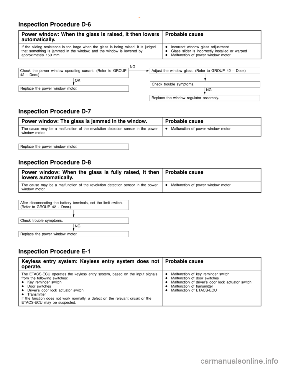
Inspection Procedure D-6
Power window: When the glass is raised, it then lowers
automatically.Probable cause
If the sliding resistance is too large when the glass isbeing raised, it is judged
that something is jammed in the window, and the window is lowered by
approximately 150 mm.DIncorrect window glass adjustment
DGlass slider is incorrectly installed or warped
DMalfunction of power window motor
OK
Replace the power window motor.NG
Replace the window regulator assembly.
Check trouble symptoms.
Check the power window operating currant. (Refer to GROUP
42 – Door.)NGAdjust the window glass. (Refer to GROUP 42 – Door.)
Inspection Procedure D-7
Power window: The glass is jammed in the window.Probable cause
The cause may be a malfunction of the revolution detection sensor in the power
window motor.DMalfunction of power window motor
Replace the power window motor.
Inspection Procedure D-8
Power window: When the glass is fully raised, it then
lowers automatically.Probable cause
The cause may be a malfunction of the revolution detection sensor in the power
window motor.DMalfunction of power window motor
NG
Replace the power window motor.
Check trouble symptoms.
After disconnecting the battery terminals, set the limit switch.
(Refer to GROUP 42 - Door.)
Inspection Procedure E-1
Keyless entry system: Keyless entry system does not
operate.Probable cause
The ETACS-ECU operates the keyless entry system, based on the input signals
from the following switches:
DKey reminder switch
DDoor switches
DDriver’s door lock actuator switch
DTransmitter
If the function does not work normally, a defect on the relevant circuit or the
ETACS-ECU may be suspected.DMalfunction of key reminder switch
DMalfunction of door switches
DMalfunction of driver’s door lock actuator switch
DMalfunction of transmitter
DMalfunction of ETACS-ECU
www.WorkshopManuals.co.uk
Purchased from www.WorkshopManuals.co.uk