2000 MITSUBISHI MONTERO MOTOR
[x] Cancel search: MOTORPage 218 of 1839

GDI -General Information13A-4
SELF-DIAGNOSIS FUNCTION
DWhen an abnormality is detected in one
of the sensors or actuators related to
emission control, the engine warning lamp
(check engine lamp) illuminates or flashes
as a warning to the driver.
DWhen an abnormality is detected in one
of the sensors or actuators, a diagnosis
code corresponding to the abnormality is
output.
DThe engine-ECU records the engine
operating condition when the diagnosis
code is set. This data is called “freezeframe” data.
This data can be read by using the MUT-II,
and can then be used in simulation tests
for troubleshooting.
DThe RAM data inside the engine-ECU
related to the sensors and actuators can
be read by means of the MUT-II. In addition,
the actuators can be force-driven under
certain circumstances.
OTHER CONTROL FUNCTIONS
1. Fuel Pump Control
Turns the fuel pump relay ON so that current
is supplied to the fuel pump while the engine
is cranking or running.
2. A/C Relay Control
Turns the compressor clutch of the A/C
ON and OFF.3. Purge Control Solenoid Valve Control
Refer to GROUP 17.
4. EGR Control Servo Control
Refer to GROUP 17.
GENERAL SPECIFICATIONS
ItemsSpecifications
Throttle bodyThrottle bore mm65
Throttle position sensorVariable resistor type
Throttle valve control servoBrushless DC-motor type
Engine-ECUIdentification model No.E2T79271
E2T79272
Engine-Identification model No.E2T76277
A/T-ECU
E2T76278
www.WorkshopManuals.co.uk
Purchased from www.WorkshopManuals.co.uk
Page 219 of 1839

GDI -General Information13A-5
Items Specifications
SensorsAir flow sensorKarman vortex type
Barometric pressure sensorSemiconductor type
Intake air temperature sensorThermistor type
Engine coolant temperature sensorThermistor type
Oxygen sensorZirconia type
Accelerator pedal position sensor (1st
and 2nd channels)Variable resistor type
Accelerator pedal position switchRotary contact type, within accelerator pedal position
sensor (1st channel)
Vehicle speed sensorMagnetic resistive element type
Inhibitor switchContact switch type
Camshaft position sensorHall element type
Crank angle sensorHall element type
Detonation sensorPiezoelectric type
Fuel pressure sensorMetallic membrane type
Power steering fluid pressure switchContact switch type
ActuatorsEngine control relay typeContact switch type
Fuel pump relay typeContact switch type
Injector driver control relayContact switch type
Injector type and numberElectromagnetic type, 6
Injector identification markDIM 1070
Throttle valve control servo relayContact switch type
Throttle valve control servoBrushless DC-motor type
EGR valveStepper motor type
Purge control solenoid valveDuty cycle type solenoid valve
Fuel pressure
regulator (low
pressure)Regulator pressure kPa329
Fuel pressure
regulator
(high pres-
sure)Regulator pressure MPa5.0
www.WorkshopManuals.co.uk
Purchased from www.WorkshopManuals.co.uk
Page 274 of 1839
GDI -Troubleshooting
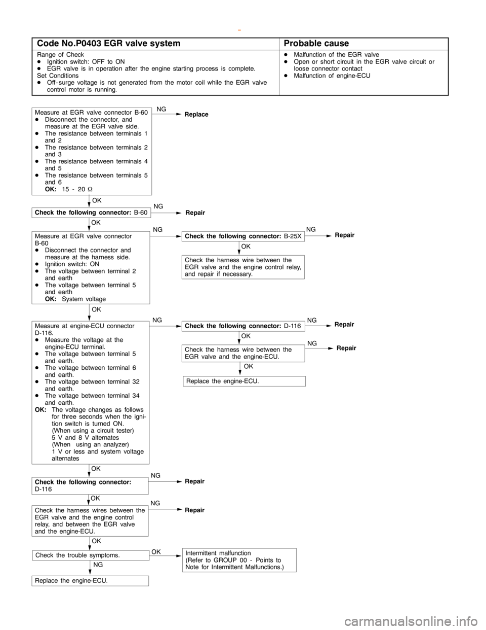
Code No.P0403 EGR valve systemProbable cause
Range of Check
DIgnition switch: OFF to ON
DEGR valve is in operation after theengine startingprocess is complete.
Set Conditions
DOff - surge voltage is not generated from the motor coil while the EGR valve
control motor is running.DMalfunction of the EGR valve
DOpen or short circuit in the EGR valve circuit or
loose connector contact
DMalfunction of engine-ECU
Measure at EGR valve connector B-60
DDisconnect the connector, and
measure at the EGR valve side.
DThe resistance between terminals 1
and 2
DThe resistance between terminals 2
and 3
DThe resistance between terminals 4
and 5
DThe resistance between terminals 5
and 6
OK:
15 - 20WNG
Replace
OK
Check the harness wire between the
EGR valve and theengine controlrelay,
and repair if necessary.
NG
Replace the engine-ECU.
OK
NG
Check the following connector:
B-25XNG
Repair
OK
Check the following connector:
B-60NG
Repair
OK
Measure at engine-ECU connector
D-116.
DMeasure the voltage at the
engine-ECU terminal.
DThe voltage between terminal 5
and earth.
DThe voltage between terminal 6
and earth.
DThe voltage between terminal 32
and earth.
DThe voltage between terminal 34
and earth.
OK:
The voltage changes as follows
for three seconds when the igni-
tion switch is turned ON.
(When using a circuit tester)
5 V and 8 V alternates
(When using an analyzer)
1 V or less and system voltage
alternatesNGCheck the following connector:
D-116NG
Repair
OK
Check the harness wire between the
EGR valve and the engine-ECU.
OK
Check the following connector:
D-116NG
Repair
OK
Check the harness wires between the
EGR valve and theengine control
relay, and between the EGR valve
and the engine-ECU.NG
Repair
OK
Check the trouble symptoms.OKIntermittent malfunction
(Refer to GROUP 00 - Points to
Note for Intermittent Malfunctions.)NG
Repair
OK
Replace the engine-ECU.
Measure at EGR valve connector
B-60
DDisconnect the connector and
measure at the harness side.
DIgnition switch: ON
DThe voltage between terminal 2
and earth
DThe voltage between terminal 5
and earth
OK:
System voltage
www.WorkshopManuals.co.uk
Purchased from www.WorkshopManuals.co.uk
Page 279 of 1839
GDI -Troubleshooting
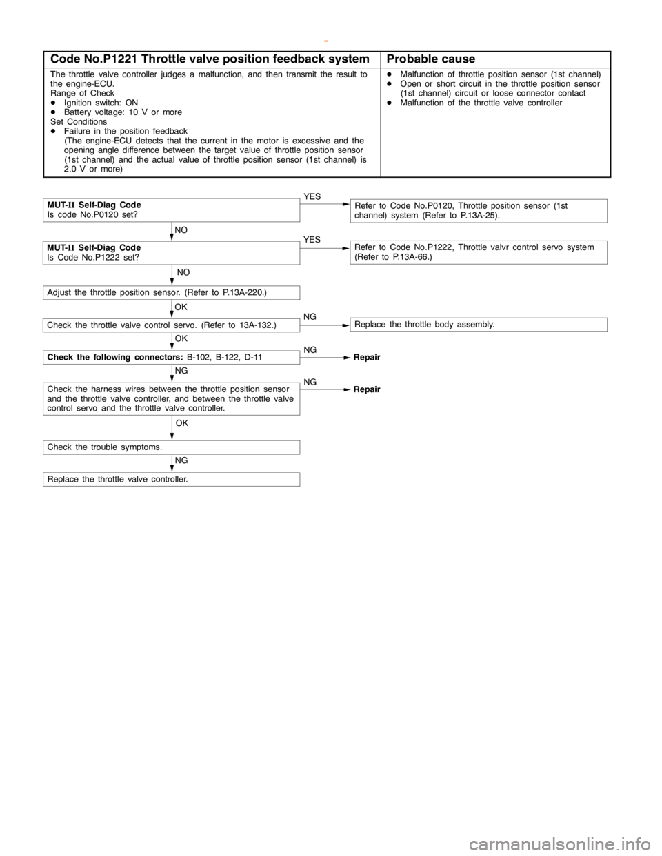
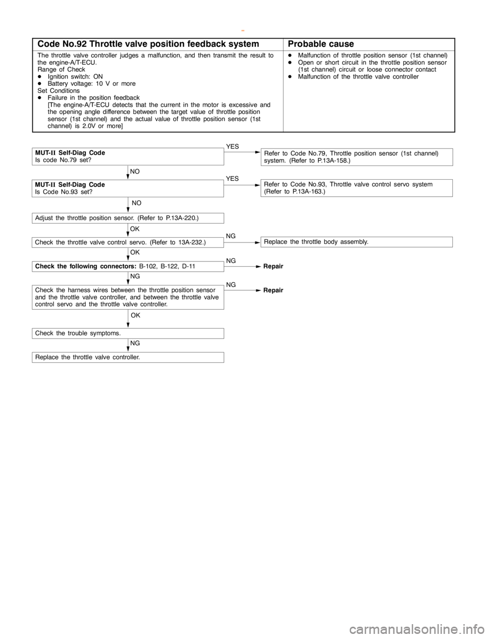
Code No.P1221 Throttle valve position feedback systemProbable cause
The throttle valve controller judges a malfunction, and then transmit the result to
the engine-ECU.
Range of Check
DIgnition switch: ON
DBattery voltage: 10 V or more
Set Conditions
DFailure in the position feedback
(The engine-ECU detects that the current in the motor isexcessive and the
opening angle difference between the targetvalue of throttle position sensor
(1st channel) and the actual value of throttle position sensor (1st channel) is
2.0 V or more)DMalfunction of throttle position sensor (1st channel)
DOpen or short circuit in the throttle position sensor
(1st channel) circuit or loose connector contact
DMalfunction of the throttle valve controller
NG
Replace the throttle valve controller.
OK
Check the trouble symptoms.
NG
Check the harness wires between the throttle position sensor
and the throttle valve controller, and between the throttle valve
control servo and the throttle valve controller.NG
Repair
NO
Adjust the throttle position sensor. (Refer to P.13A-220.)
MUT-
IISelf-Diag Code
Is code No.P0120 set?YESRefer to Code No.P0120, Throttle position sensor (1st
channel) system (Refer to P.13A-25).
NO
MUT-
IISelf-Diag Code
Is Code No.P1222 set?YESRefer to Code No.P1222, Throttle valvr control servo system
(Refer to P.13A-66.)
OK
Check the following connectors:
B-102, B-122, D-11NG
Repair
OK
Check the throttle valve control servo. (Refer to 13A-132.)NGReplace the throttle body assembly.
www.WorkshopManuals.co.uk
Purchased from www.WorkshopManuals.co.uk
Page 309 of 1839
GDI -Troubleshooting
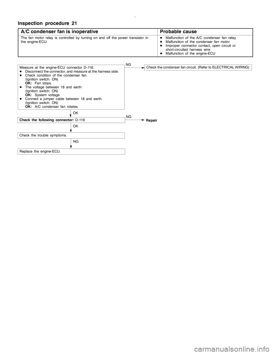
Inspection procedure 21
A/C condenser fan is inoperative
Probable cause
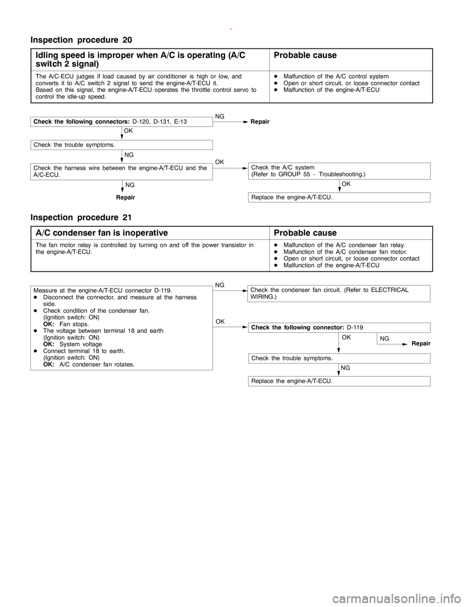
The fan motor relay is controlled by turning on and off the power transistor in
the engine-ECU.DMalfunction of the A/C condenser fan relay.
DMalfunction of the condenser fan motor.
DImproper connector contact,opencircuit or
short-circuited harness wire
DMalfunction of the engine-ECU
OK
Replace the engine-ECU.NG
Repair
OK
Check the trouble symptoms.
Check the following connector:
D-116
Measure at the engine-ECU connector D-116.
DDisconnect the connector, and measure at the harness side.
DCheck condition of the condenser fan.
(Ignition switch: ON)
OK:
Fan stops.
DThe voltage between 18 and earth
(Ignition switch: ON)
OK:
System voltage
DConnect a jumper cable between 18 and earth.
(Ignition switch: ON)
OK:
A/C condenser fan rotates.NGCheck the condenser fan circuit. (Refer to ELECTRICAL WIRING)
NG
www.WorkshopManuals.co.uk
Purchased from www.WorkshopManuals.co.uk
Page 324 of 1839

GDI -Troubleshooting
ACTUATOR TEST REFERENCE TABLE
Item
No.Inspection
itemDrive contentsInspection contentsNormal conditionInspection
procedure
No.Reference
page
01InjectorsCut fuel to No. 1
injectorEngine:
After havingIdling condition
becomes differentCode No.
P020113A-38
02Cut fuel to No. 2
injector
warmed up/Engine
is idling
(Cut the fuel supply(becomes unsta-
ble).
Code No.
P020213A-40
03Cut fuel to No. 3
injectorto each injector in
turn and check
cylinders whichCode No.
P020313A-42
04Cut fuel to No. 4
injectordon’t affect idling.)Code No.
P020413A-44
05Cut fuel to No. 5
injectorCode No.
P020513A-46
06Cut fuel to No. 6
injectorCode No.
P020613A-48
07Fuel pump
(low pressure)Fuel pump
operates and
fuel is recirculated.Ignition switch: ONSound of opera-
tion is heard.Procedure
No. 2913A-101
08Purge
control
solenoid valveSolenoid valve
turns from OFF to
ON.Ignition switch: ONSound of opera-
tion can be heard
when solenoid
valve is
driven.Code No.
P044313A-62
17Basic ignition
timingSet the engine-
ECU to ignition
timing adjustment
modeIdling after engine
warm up5_BTDC--
21Condenser fanDrive the fan motorIgnition switch: ONThe fan motor
operatesProcedure
No.2113A-95
34Electronic-
controlled
throttle valve
systemStop the throttle
control servo.Ignition switch: ONThrottle valve is
opened slightly.Code No.
P122013A-64
www.WorkshopManuals.co.uk
Purchased from www.WorkshopManuals.co.uk
Page 376 of 1839
Page 401 of 1839
