2000 MITSUBISHI MONTERO MOTOR
[x] Cancel search: MOTORPage 1732 of 1839

Page 1738 of 1839

SWS -Troubleshooting54B-52
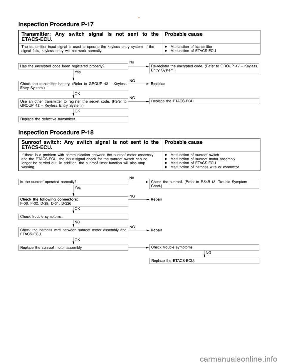
Inspection Procedure P-17
Transmitter: Any switch signal is not sent to the
ETACS-ECU.Probable cause
The transmitter input signal is used to operate the keyless entry system. If the
signal fails, keyless entry will not work normally.DMalfunction of transmitter
DMalfunction of ETACS-ECU
Ye s
NG
Replace
OK
Replace the defective transmitter.
OK
Use an other transmitter to register the secret code. (Refer to
GROUP 42 – Keyless Entry System.)NGReplace the ETACS-ECU.
Check the transmitter battery. (Refer to GROUP 42 – Keyless
Entry System.)
Has the encrypted codebeen registered properly?NoRe-register the encrypted code. (Refer to GROUP 42 – Keyless
Entry System.)
Inspection Procedure P-18
Sunroof switch: Any switch signal is not sent to the
ETACS-ECU.Probable cause
If there is a problem with communication between the sunroof motor assembly
and the ETACS-ECU, the input signal check for the sunroof switch can no
longer be carried out. In addition, the sunroof timer function will also stop
working.DMalfunction of sunroof switch
DMalfunction of sunroof motor assembly
DMalfunction of ETACS-ECU
DMalfunction of harness wire or connector.
Ye s
NG
Repair
NG
Replace the ETACS-ECU.
OK
Replace the sunroof motor assembly.Check trouble symptoms.
NG
Check the harness wire between sunroof motor assembly and
ETACS-ECU.NG
Repair
OK
Check trouble symptoms.
Check the following connectors:
F-06, F-02, D-29, D-31, D-226
Is the sunroof operated normally?NoCheck the sunroof. (Refer to P.54B-13, Trouble Symptom
Chart.)
www.WorkshopManuals.co.uk
Purchased from www.WorkshopManuals.co.uk
Page 1748 of 1839

55A-2
HEATER, AIR
CONDITIONER AND
VENTILATION
CONTENTS
SERVICE SPECIFICATIONS 3.................
LUBRICANTS 3..............................
TROUBLESHOOTING
TROUBLESHOOTING
ON-VEHICLE SERVICE 9.....................
Refrigerant Level Test through Performance Test 9.
Magnetic Clutch Test 10.........................
Receiver Drier Test 10..........................
Compressor Drive Belt Adjustment 10.............
Dual Pressure Switch Check 10..................
Charging 11...................................
Performance Test 15............................
Front Blower Relay and Rear Blower Relay
Continuity Check 18............................
Continuity Check of A/C Compressor Relay and
Condernser Fan Relay 18.......................
PTC Heater Relay Continuity Check 19...........
Idle-up Operation Check
Vacuum Actuator Check
Idle-up Solenoid Valve Check 21.................
Clean Air Filter Replacement Procedure 22........
FRONT A/C 23..............................
Air Conditioner Control Panel Assembly and
A/C Switch 23.................................
Heater Unit and Blower Assembly 26.............
Blower Motor and Resistor 29....................
Inside/Outside Air Changeover Damper Motor 30...
Automatic Compressor-ECU and
Air Thermo Sensor Assembly 31.................
REAR HEATER AND REAR COOLER 32.....
Rear A/C Switch, Front Rear Fan Switch 32.......
Rear A/C Control Unit 34........................
Rear Heater Unit 34............................
Rear Heater Unit and Rear Blower Assembly 37....
HEAT SWITCH 40...........................
COMPRESSOR 41...........................
CONDENSER ASSEMBLY AND
CONDENSER FAN 45........................
REFRIGERANT LINE 47.....................
ENGINE COOLANT TEMPERATURE SWITCH
51 ..........................................
IDLE-UP SYSTEM 53........................
DUCTS 54..................................
VENTILATION 56............................
www.WorkshopManuals.co.uk
Purchased from www.WorkshopManuals.co.uk
Page 1750 of 1839

HEATER, AIR CONDITIONER AND VENTILATION - Troubleshooting55A-4
TROUBLESHOOTING
Trouble symp-
tomProbable causeRemedyRefer-
ence
page
The air condi-Malfunction of fuseReplace the fuse.–
tioner does notMalfunction of harness or connectorRepair the harness or connector.–work.
Refrigerant leak or overfilling of refrigerantReplenish the refrigerant, repair the leak
or take out some of the refrigerant.–
A/C compressor relay is defective.Replace the A/C compressor relay.55A-18
The A/C compressor magnetic clutch is
defective.Replace the A/C compressor.55A-10
The dual pressure switch is defective.Replace the dual-pressure switch.55A-10
The A/C switch is defective.Replace the heater control assembly.55A-24
The blower switch is defective.Replace the heater control assembly.55A-24
The air thermo sensor is defective.Replace the automatic compressor-ECU
and the air thermo sensor assembly.55A-31
The automatic compressor-ECU is defec-
tive.Replace the automatic compressor-ECU
and the air thermo sensor assembly.55A-6
The engine-ECU is defective.Replace the engine-ECU.–
When the A/C
is operating,Refrigerant leakReplenish the refrigerant and repair the
leak.–
temperature
inside the pas-The dual pressure switch is defective.Replace the dual-pressure switch.55A-10inside the pas-
senger
The condenser fan relay is defective.Replace the condenser fan relay.55A-18compartment
doesn’t de-
A/C compressor relay is defective.Replace the A/C compressor relay.55A-18
crease (cool
air is not
emitted).The A/C compressor magnetic clutch is
defective.Replace the A/C compressor.55A-10
When the A/C
is operating,
temperature
inside the pas-
senger
compartment
doesn’t in-
crease (warm
air is not
emitted).Malfunction of the air thermo sensorReplace the automatic compressor-ECU
and the air thermo sensor assembly.55A-31
The blowerMalfunction of fuseReplace the fuse.–
motor does notMalfunction of harness or connectorRepair the harness or connector.–run.
The blower relay is defective.Replace the blower relay.55A-18
The blower motor is defective.Replace the blower motor.55A-29
The blower switch is defective.Replace the heater control assembly.55A-24
Malfunction of the resistorReplace the resistor.55A-29
The automatic compressor-ECU is defec-
tive.Replace the automatic compressor-ECU
and the air thermo sensor assembly.55A-6
www.WorkshopManuals.co.uk
Purchased from www.WorkshopManuals.co.uk
Page 1753 of 1839

HEATER, AIR CONDITIONER AND VENTILATION - Troubleshooting55A-7
TROUBLESHOOTING
Trouble symp-
tomProbable causesRemedyRefer-
ence
page
The rear cool-Malfunction of fuseReplace the fuse.–
er does notMalfunction of harness or connectorRepair the harness or connector.–operate.
Refrigerant leak or overfilling of refrigerantReplenish the refrigerant, repair the leak
or take out some of the refrigerant.–
Malfunction of the rear A/C switchReplace the rear A/C switch.55A-32
Malfunction of the front rear fan switchReplace the front rear fan switch.55A-33
Malfunction of the air thermo sensorReplace the air thermo sensor.55A-39
Malfunction of the rear blower relayReplace the rear blower relay.55A-18
The rear blower motor is defective.Replace the rear blower motor.55A-40
The rear cooler control unit is defective.Replace the rear cooler control unit.55A-34
When the rear
cooler is oper-
ating, temper-
ature inside
the passenger
compartment
does not de-
crease(cool air
is not emitted).Refrigerant leakReplenish the refrigerant and repair the
leak.–
When the rear
heater is oper-
ating, temper-
ature inside
the passenger
compartment
does not in-
crease(warm
air is not
emitted).Malfunction of the air thermo sensorReplace the air thermo sensor.55A-39
The blowerMalfunction of fuseReplace the fuse.–
motor does notMalfunction of harness or connectorRepair the harness or connector.–run.
Malfunction of the rear blower relayReplace the blower relay.55A-18
The rear blower motor is defective.Replace the blower motor.55A-40
Malfunction of the rear A/C switchReplace the rear A/C switch.55A-32
Malfunction of the front rear fan switchReplace the front rear fan switch.55A-33
Malfunction of the resistorReplace the resistor.55A-35
The rear cooler control unit is defective.Replace the rear cooler control unit.55A-34
The blowerMalfunction of fuseReplace the fuse.–
motor does notMalfunction of harness or connectorRepair the harness or connector.–stop running.
Malfunction of the rear A/C switchReplace the rear A/C switch.55A-32
Malfunction of the front rear fan switchReplace the front rear fan switch.55A-33
Malfunction of the resistorReplace the resistor.55A-35
The rear cooler control unit is defective.Replace the rear cooler control unit.55A-34
www.WorkshopManuals.co.uk
Purchased from www.WorkshopManuals.co.uk
Page 1804 of 1839

55B-1
HEATER, AIR
CONDITIONER AND
VENTILATION
CONTENTS
SERVICE SPECIFICATIONS 2.................
LUBRICANTS 2..............................
SPECIAL TOOLS 3...........................
TROUBLESHOOTING
TROUBLESHOOTING
ON-VEHICLE SERVICE 24...................
Magnetic Clutch Test 24.........................
Idle Up Operation Check
FRONT A/C 25..............................
Automatic A/C Control Panel Assembly
(A/C-ECU) 25..................................Blower Linear Controller 26......................
Air Mix Damper Motor and
Air Outlet Changeover Damper Motor 27..........
Heater Water Temperature Sensor 29.............
PHOTO SENSOR 30........................
OUTSIDE AIR TEMPERATURE SENSOR 30..
REAR A/C 30...............................
Electric Motor for Air Outlet Changeover
Damper 30....................................
REFRIGERANT LINE 31.....................
COMPRESSOR 33...........................
www.WorkshopManuals.co.uk
Purchased from www.WorkshopManuals.co.uk
Page 1809 of 1839

HEATER, AIR CONDITIONER AND VENTILATION -Troubleshooting
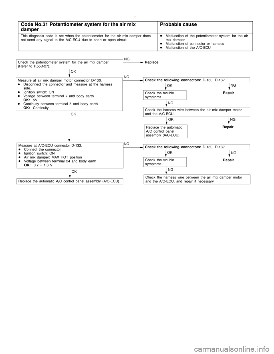
Code No.31 Potentiometer system for the air mix
damperProbable cause
This diagnosis code is set when the potentiometer for the air mix damper does
not send any signal to the A/C-ECU due to short oropencircuit.DMalfunction of the potentiometer system for the air
mix damper
DMalfunction of connector or harness
DMalfunction of the A/C-ECU
NG
Repair
NG
Repair
NG
Check the harness wire between the air mix damper motor
and the A/C-ECU, and repair if necessary.
OK
Replace the automatic A/C control panelassembly (A/C-ECU).
NG
Repair
OK
Replace the automatic
A/C control panel
assembly (A/C-ECU).
OK
Check the trouble
symptoms.
OK
Measure at A/C-ECU connector D-132.
DConnect the connector.
DIgnition switch: ON
DAir mix damper: MAX HOT position
DVoltage between terminal 24 and body earth
OK:0.7 - 1.3 VNGCheck the following connectors:D-130, D-132
NG
Check the harness wire between the air mix damper motor
and the A/C-ECU.
OK
Check the trouble
symptoms.
OK
Measure at air mix damper motor connector D-130.
DDisconnect the connector and measure at the harness
side.
DIgnition switch: ON
DVoltage between terminal 7 and body earth
OK:5V
DContinuity between terminal 5 and body earth
OK:ContinuityNGCheck the following connectors:D-130, D-132
Check the potentiometer system for the air mix damper
(Refer to P.55B-27).NG
Replace
www.WorkshopManuals.co.uk
Purchased from www.WorkshopManuals.co.uk
Page 1810 of 1839

HEATER, AIR CONDITIONER AND VENTILATION -Troubleshooting
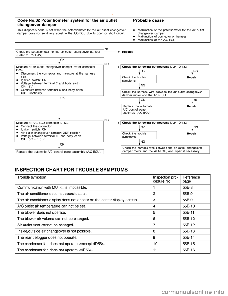
Code No.32 Potentiometer system for the air outlet
changeover damperProbable cause
This diagnosis code is set when the potentiometer for the air outlet changeover
damper does not send any signal to the A/C-ECU due toopen orshort circuit.DMalfunction of the potentiometer for the air outlet
changeover damper
DMalfunction of connector or harness
DMalfunction of the A/C-ECU
NG
Repair
NG
Repair
NG
Check the harness wire between the air outlet changeover
damper motor and the A/C-ECU, and repair if necessary.OK
Replace the automatic A/C control panelassembly (A/C-ECU).
NG
Repair
OK
Replace the automatic
A/C control panel
assembly (A/C-ECU).
OK
Check the trouble
symptoms.
OK
Measure at A/C-ECU connector D-132.
DConnect the connector.
DIgnition switch: ON
DAir outlet changeover damper: DEF position
DVoltage between terminal 32 and body earth
OK:0.7 - 1.3 VNGCheck the following connectors:D-24, D-132
NG
Check the harness wire between the air outlet changeover
damper motor and the A/C-ECU.
OK
Check the trouble
symptoms.
OK
Measure at air outlet changeover damper motor connector
D-24.
DDisconnect the connector and measure at the harness
side.
DIgnition switch: ON
DVoltage between terminal 7 and body earth
OK:5V
DContinuity between terminal 5 and body earth
OK:ContinuityNGCheck the following connectors:D-24, D-132
Check the potentiometer for the air outlet changeover damper
(Refer to P.55B-27).NG
Replace
INSPECTION CHART FOR TROUBLE SYMPTOMS
Trouble symptomInspection pro-
cedure No.Reference
page
Communication with MUT-IIis impossible.155B-8
The air conditioner does not operate at all.255B-9
The air conditioner display does not appear on the center display screen.355B-9
A/C outlet air temperature can not be set.455B-10
The blower does not operate.555B-11
The blower air volume can not be changed.655B-12
Air outlet vent cannot be changed.755B-12
Inside/outside air changeover is not possible.855B-13
The rear defogger does not operate.955B-14
The condenser fan does not operate
The condenser fan does not operate <4D56>.1155B-16
www.WorkshopManuals.co.uk
Purchased from www.WorkshopManuals.co.uk