2000 MITSUBISHI MONTERO ECU
[x] Cancel search: ECUPage 658 of 1839

DIESEL FUEL <4D5-stepIII>-Troubleshooting13E-48
Terminal
No.Normal condition: Inspection conditions (engine status) Check item
88Boost air temperature
sensorIgnition switch: ONIntake air temperature:
0_C3.2 - 3.8 V
Intake air temperature:
20_C2.3 - 2.9 V
Intake air temperature:
40_C1.4 - 2.0 V
Intake air temperature:
80_C0.4 - 1.0 V
89Crank angle sensorEngine: Idling (Use a digital voltage meter to check.)0V↔5V
(repeat the change)
90EGR valve position
sensor
Engine: After warm-
inguptheengine
Idling under no load2.3 - 3.3 V
sensoring up the engineEngine is suddenly racedMomentarily drops from
voltage during idling
91Parking switchIgnition switch: ON
(Enginestops)
Parking brake: ON0-1V
(Engine stops)Parking brake: OFFSystem voltage
CHECK CHART FOR RESISTANCE AND CONTINUITY
BETWEEN TERMINALS
1. Turn the ignition switch to LOCK (OFF) position.
2. Disconnect the engine-ECU connector.
3. Measure the resistance and check for continuity between
the terminals of the engine-ECU harness-side connector
while referring to the check chart.
NOTE
(1) When measuring resistance and checking continuity,
a harness for checking contact pin pressure should
be used instead of inserting a test probe.
(2) Checking need not be carried out in the order given
in the chart.
Caution
If the terminals that should be checked are mistaken,
or if connector terminals are not correctly shorted
to earth, damage may be caused to the vehicle wiring,
sensors, engine-ECU and/or ohmmeter.
Be careful to prevent this!
4. If the ohmmeter shows any deviation from the standard
value, check the corresponding sensor, actuator and
related electrical wiring, and then repair or replace.
5. After repair or replacement, recheck with the ohmmeter
to confirm that the repair or replacement has corrected
the problem.
www.WorkshopManuals.co.uk
Purchased from www.WorkshopManuals.co.uk
Page 710 of 1839

A
IR CLE A NER
R EM OVA L AND IN STA LLA TIO N
C au tio n
P arts mark ed by *are mad e of re cycle d -p ap er m ix ed pla stic mate ria l, so observ e th e fo llo w in g
p re cau tio ns.
1 . Avo id an y sh ock or lo ad to th ese parts when re m ovin g an d in sta llin g th em .
2 . Engag e th e case hin ges secu re ly when assem blin g th ese parts .
N O TE
P arts m ark e d by *are m ade ofre cycle d-p aper m ix e d pla stic m ate ria l, so ca n be dis p ose d ofb y in cin era tio n.
Page 735 of 1839

INTAKE AND EXHAUST -General Information/Service Specifications/Sealant15-3
At starting and driving at low speed, the duty control
value of the variable geometry solenoid valve is
increased to apply the vacuum pressure of the
vacuum pump to the variable geometry actuator.
Applying the vacuum pressure to the variable
geometry actuator pulls the actuator rod so that
it can move towards the direction of closing the
variable nozzle of the variable geometry
turbocharger. As closing the nozzle reduces the
exhaust gas mass, the speed of exhaust gas flow
will be increased and efficiency will be improved.
Since the characteristic of boost pressure becomes
a low speed type, boost pressure will suddenly
rise from low speed.
At driving at high speed, the duty control value
of the variable geometry solenoid valve is
decreased to reduce the vacuum pressure from
the vacuum pump so that the actuator rod can
return to the deactivated status and move towards
the direction of opening the nozzle of the variable
geometry turbocharger.Opening the nozzle allows the characteristic of
boost pressure to become a high speed type so
that the appropriate boost pressure can be
maintained.
Therefore, boost pressure can be controlled by
appropriate duty control of the variable geometry
solenoid valve. The engine-ECU calculates the
correct boost pressure based on the engine speed
and fuel injection amount. Furthermore, the duty
control of the variable geometry solenoid valve is
given feedback of the signals from the variable
geometry control pressure sensor and the boost
pressure sensor so that the variable nozzle opening
angle of the variable geometry turbocharger can
be quickly adjusted to obtain the desired boost
pressure.
SERVICE SPECIFICATIONS
ItemsStandard value
Variable geometry actuator activation vacuum
(Approximately 1 mm stroke) kPaApproximately 10.5 - 12.5
Variable geometry solenoid valve coil resistance
(at 20°C)Ω29 - 35
SEALANT
ItemSpecified sealantRemarks
Thread of the intake manifold mounting
bolts3M Stud Locking No.4170 or equivalentAnaerobic sealant
www.WorkshopManuals.co.uk
Purchased from www.WorkshopManuals.co.uk
Page 749 of 1839

16-1
ENGINE
ELECTRICAL
CONTENTS
CHARGING SYSTEM 2................
GENERAL INFORMATION 2................
SERVICE SPECIFICATIONS 3..............
SPECIAL TOOL 4.........................
ON-VEHICLE SERVICE 5..................
Alternator Output Line Voltage Drop Test 5....
Output Current Test 6.......................
Regulated Voltage Test 8....................
Waveform Check Using An Analyzer 11.......
ALTERNATOR 13.........................
STARTING SYSTEM 23................
GENERAL INFORMATION 23..............
SERVICE SPECIFICATIONS 24............
STARTER MOTOR 24.....................
IGNITION SYSTEM 37.................
GENERAL INFORMATION 37..............
SERVICE SPECIFICATIONS 38............
SPECIAL TOOL 38.......................
ON-VEHICLE SERVICE 38................
Ignition Coil (With Built-in Power Transistor)
Check 38...................................
Spark Plug Check and Cleaning 39...........
Ignition Failure Sensor Check 40.............
Camshaft Position Sensor Check, Crank angle
Sensor Check, Detonation Sensor Check 40...
IGNITION COIL <6G7> 41.................
CRANKSHAFT ANGLE SENSOR
<6G7> 42................................
CAMSHAFT POSITION SENSOR
<6G7> 42................................
DETONATION SENSOR <6G7> 43.........
GLOW SYSTEM 44....................
GENERAL INFORMATION 44..............
SERVICE SPECIFICATIONS 45............
ON-VEHICLE SERVICE 45................
Self-regulating Glow System Check 45........
Glow & EGR Control Unit Check 48..........
Engine ECU Check 49.......................
Glow Plug Relay Check 50..................
Glow Plug Check 51........................
Engine Coolant Temperature Sensor
Check 51...................................
GLOW PLUG 52..........................
www.WorkshopManuals.co.uk
Purchased from www.WorkshopManuals.co.uk
Page 801 of 1839

ENGINE ELECTRICAL -Glow System <4D5-StepIII>16-1
GROUP 16
ENGINE ELECTRICAL
GLOW SYSTEM <4D5-STEPIII>
GENERAL
OUTLINE OF CHANGE
Glow system control is now carried out by the engine-ECU to correspond to the adoption of an
electronically-controlled fuel injection system.
Refer to GROUP 13E - Troubleshooting for details on measuring the ECU terminal voltage as a result
of this.
www.WorkshopManuals.co.uk
Purchased from www.WorkshopManuals.co.uk
Page 804 of 1839

17-2
EVAPORATIVE EMISSION CONTROL
SYSTEM 36..............................
General Information 36......................
System Diagram 36.........................
Component Location 36......................
Purge Control System Check 37..............
Purge Port Vacuum Check 37................
Purge Control Solenoid Valve Check 38.......
EXHAUST GAS RECIRCULATION (EGR)
SYSTEM 39..............................
General Information 39......................
Operation 39................................
System Diagram 39.........................
Component Location 39......................
Exhaust Gas Recirculation (EGR) Control
System Check 40...........................
EGR Valve (Stepper Motor) Check 40........
EGR VALVE 42...........................
CANISTER 43............................
CATALYTIC CONVERTER 44..............
General Information 44......................
EMISSION CONTROL SYSTEM
<4D5> 45.............................
GENERAL INFORMATION 45..............
SERVICE SPECIFICATIONS 45............
SEALANT 45.............................
SPECIAL TOOL 45.......................
EXHAUST GAS RECIRCULATION (EGR)
SYSTEM 46..............................
General Information 46......................
System Diagram 46.........................
Component Location 46......................
Function Check 47..........................
EGR Solenoid Valve Operation Check 47.....
EGR Solenoid Valve Resistance Check 48....
Lever Position Sensor (LPS) Adjustment 48...
Engine Speed Sensor Check 49..............
Engine Coolant Temperature Sensor
Check 49...................................
CHECK AT THE GLOW & EGR CONTROL
UNIT 51..................................
EMISSION CONTROL SYSTEM
<4M4-VEHICLES WITH EGR> 52........
GENERAL INFORMATION 52..............
SERVICE SPECIFICATIONS 52............
EXHAUST GAS RECIRCULATION (EGR)
SYSTEM 53..............................
General Information 53......................
System Diagram 53.........................
Component Location 53......................
Function Check 54..........................
EGR Solenoid Valve Operation Check 54.....
EGR Solenoid Valve Resistance Check 55....
Accelerator Pedal Position Sensor (APS),
Engine Coolant Temperature Sensor, Intake
Air Temperature Sensor, Fuel Temperature
Sensor Check 55............................
Check at Engine-ECU 55....................
CATALYTIC CONVERTER 55..............
General Information 55......................
www.WorkshopManuals.co.uk
Purchased from www.WorkshopManuals.co.uk
Page 812 of 1839

ENGINE AND EMISSION CONTROL -Auto-cruise Control System17-10
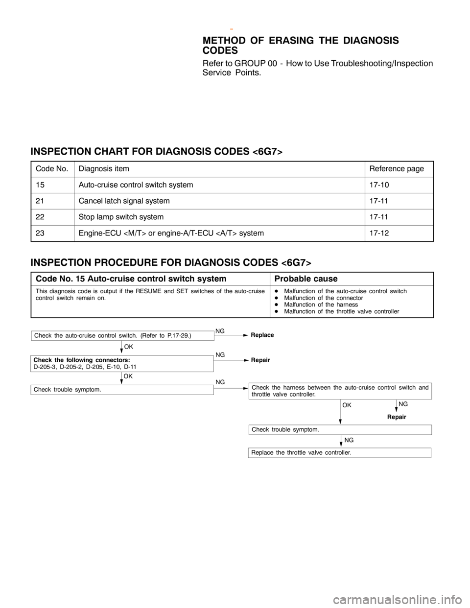
METHOD OF ERASING THE DIAGNOSIS
CODES
Refer to GROUP 00 - How to Use Troubleshooting/Inspection
Service Points.
INSPECTION CHART FOR DIAGNOSIS CODES <6G7>
Code No.Diagnosis itemReference page
15Auto-cruise control switch system17-10
21Cancel latch signal system17-11
22Stop lamp switch system17-11
23Engine-ECU
INSPECTION PROCEDURE FOR DIAGNOSIS CODES <6G7>
Code No. 15 Auto-cruise control switch systemProbable cause
This diagnosis code is output if the RESUME and SET switches of the auto-cruise
control switch remain on.DMalfunction of the auto-cruise control switch
DMalfunction of the connector
DMalfunction of the harness
DMalfunction of the throttle valve controller
Repair
Check the auto-cruise control switch. (Refer to P.17-29.)NG
Replace
OK
Check the following connectors:
D-205-3, D-205-2, D-205, E-10, D-11NG
Repair
NGCheck the harness between the auto-cruise control switch and
throttle valve controller.
NG
OK
Replace the throttle valve controller.
OK
Check trouble symptom.
Check trouble symptom.
NG
www.WorkshopManuals.co.uk
Purchased from www.WorkshopManuals.co.uk
Page 813 of 1839

ENGINE AND EMISSION CONTROL -Auto-cruise Control System17-11
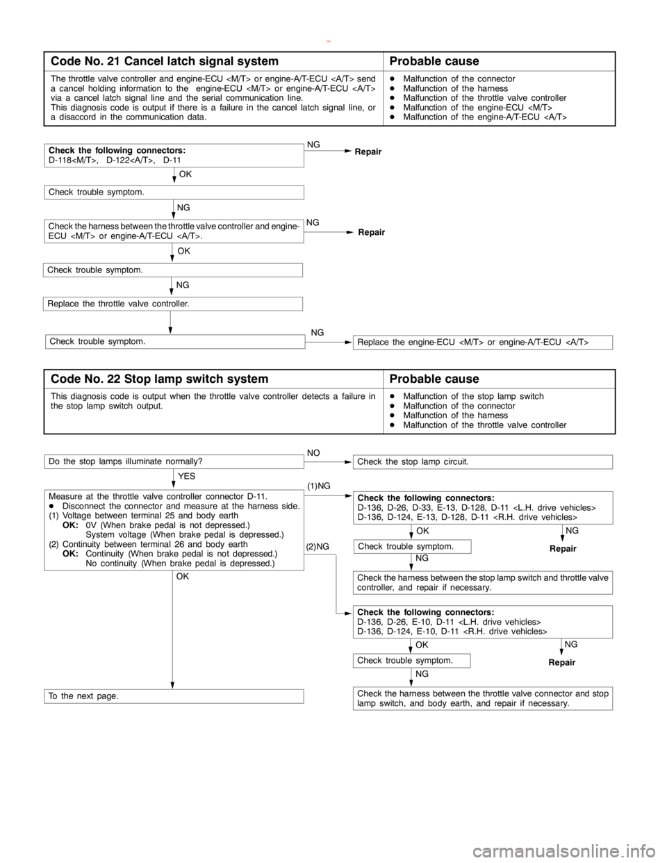
Code No. 21 Cancel latch signal systemProbable cause
The throttle valve controller and engine-ECU
a cancelholding information to the engine-ECU
via a cancel latch signal line and the serial communication line.
This diagnosis code is output if there is a failure in the cancel latch signal line, or
a disaccord in the communication data.DMalfunction of the connector
DMalfunction of the harness
DMalfunction of the throttle valve controller
DMalfunction of the engine-ECU
DMalfunction of the engine-A/T-ECU
Repair NG
RepairCheck the following connectors:
D-118
OK
Replace the throttle valve controller.
NG
NG
Check the harness between the throttle valve controller and engine-
ECU
Replace the engine-ECU
Check trouble symptom.
OK
Check trouble symptom.
Check trouble symptom.NG
Code No. 22 Stop lamp switch systemProbable cause
This diagnosis code is output when the throttle valve controller detects a failure in
the stoplampswitch output.DMalfunction of the stoplampswitch
DMalfunction of the connector
DMalfunction of the harness
DMalfunction of the throttle valve controller
(2)NG
NG
Check the harness between the throttle valve connector and stop
lampswitch, and body earth, and repair if necessary.
NG
Repair
OK
Check trouble symptom.
Measure at the throttle valve controller connector D-11.
DDisconnect the connector and measure at the harness side.
(1) Voltage between terminal 25 and body earth
OK:0V (When brakepedal is not depressed.)
System voltage (When brakepedal is depressed.)
(2) Continuity between terminal 26 and body earth
OK:Continuity (When brakepedal is not depressed.)
No continuity (When brakepedal is depressed.)NO
Do the stop lamps illuminate normally?
OK
To the next page.
Check the following connectors:
D-136, D-26, D-33, E-13, D-128, D-11
D-136, D-124, E-13, D-128, D-11
OK
Check trouble symptom.
NG
Check the harness between the stoplampswitch and throttle valve
controller, and repair if necessary.NG
Repair
Check the stoplampcircuit.
YES
(1)NG
Check the following connectors:
D-136, D-26, E-10, D-11
D-136, D-124, E-10, D-11
www.WorkshopManuals.co.uk
Purchased from www.WorkshopManuals.co.uk