2000 MITSUBISHI MONTERO ECU
[x] Cancel search: ECUPage 898 of 1839

MANUAL TRANSMISSION -4WD Indicator-ECU/Transfer-ECU22-18
Terminal No.Inspection itemInspection condition
1: Ignition switchInspection condition
2: Transfer lever positionTerminal voltage
1Free wheel engageON2HSystem voltage
switch
4H*10V
24WD detectionON2HSystem voltage
switch
4H, 4L0V
3Ignition switch (IG1)OFF-0V
ON-System voltage
6HI/LOW detection
switchONShifting from 4H to 4L
or vice versaSystem voltage
2H, 4H, 4L0V
7Free wheel clutchON4H, 4L0V
changeover solenoid
valve
2H*2System voltage
104WD Indicator lampON2H0V
4H, 4LSystem voltage
NOTE
*1:When vehicle has been moved once.
*2:Shift the lever from 4H to 2H, and then turn the ignition switch to OFF and then back to ON.
TRANSFER-ECU
Measure the terminal voltage (Refer to P.22-3).
www.WorkshopManuals.co.uk
Purchased from www.WorkshopManuals.co.uk
Page 899 of 1839

MANUAL TRANSMISSION -Gneral/Troubleshooting
GROUP 22
MANUAL TRANSMISSION
GENERAL
OUTLINE OF CHANGE
With additional vehicle with Emission Regulation Step III compatible 4D5 engine, the service procedure
different from service adjustment procedure of the vehicle with 4D5 engine has been established.
TROUBLESHOOTING
INSPECTION CHART FOR DIAGNOSIS CODE
Diagnosis
codeDiagnosis itemReference page
21Accelerator pedal position sensor (APS) system
<4D5>Open circuit/Malfunc-
tion of sensor22-1
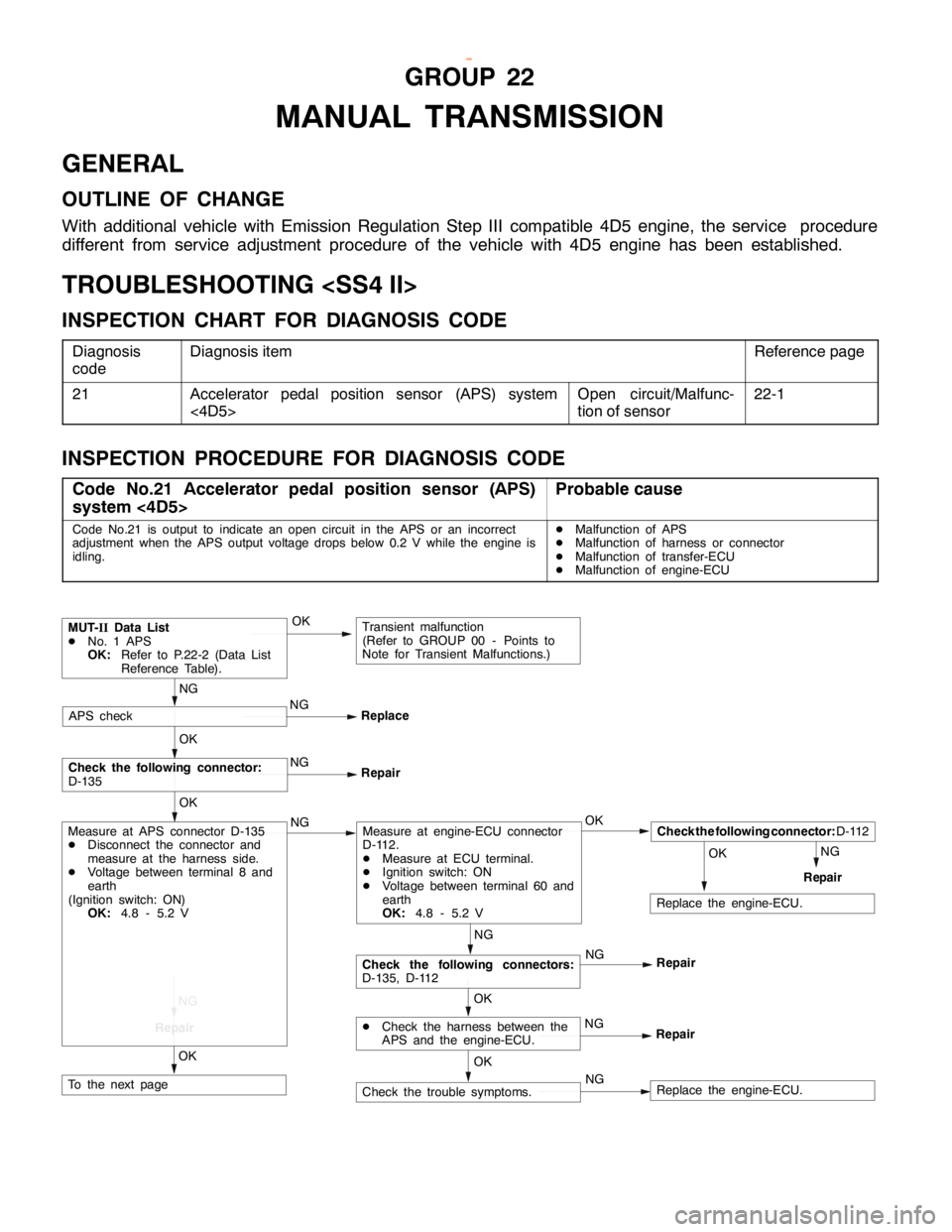
INSPECTION PROCEDURE FOR DIAGNOSIS CODE
Code No.21 Accelerator pedal position sensor (APS)
system <4D5>Probable cause
Code No.21 is output to indicate an open circuit in the APS or an incorrect
adjustment when the APS output voltage drops below 0.2 V while the engine is
idling.DMalfunction of APS
DMalfunction of harness or connector
DMalfunction of transfer-ECU
DMalfunction of engine-ECU
NGNG
NG
Repair
MUT-IIData List
DNo. 1 APS
OK:Refer to P.22-2 (Data List
Reference Table).
NG
ReplaceAPS check
OK
NG
Repair
OK
Check the following connector:
D-135
OK
OK
Check the following connector:D-112
Repair
NG
Repair
NG
Repair
OK
DCheck the harness between the
APS and the engine-ECU.
OK
Check the following connectors:
D-135, D-112
Measure at engine-ECU connector
D-112.
DMeasure at ECU terminal.
DIgnition switch: ON
DVoltage between terminal 60 and
earth
OK:4.8 - 5.2 V
NGNG
NGCheck the trouble symptoms.Replace the engine-ECU.
OK
Measure at APS connector D-135
DDisconnect the connector and
measure at the harness side.
DVoltage between terminal 8 and
earth
(Ignition switch: ON)
OK:4.8 - 5.2 V
To the next page
Transient malfunction
(Refer to GROUP 00 - Points to
Note for Transient Malfunctions.)
OK
Replace the engine-ECU.
www.WorkshopManuals.co.uk
Purchased from www.WorkshopManuals.co.uk
Page 900 of 1839

MANUAL TRANSMISSION -Troubleshooting
OKOK OK
NG
NG
NG(1), (2)
NG
Check the following connector:D-112Repair OK
DCheck the harness between the
APS and the engine-ECU, and
repair if necessary.OK
Measure at transfer-ECU connector
E-105
DMeasure at ECU terminals.
DIgnition switch: ON
DVoltage between terminal 5 and
earth
OK:Fully close the accelerator
985 - 1,085 mV
fully open the accelerator
4,000 mV or more
Check the following connector:E-105
Check the trouble symptoms.OK
Check the following connectors:
E-105, E-113 NG
Replace the transfer-ECU. OK
NGRepair
Check the harness between the APS
and the transfer-ECU, and repair if
necessary.
Check the harness between the APS
and the transfer-ECU, and repair if
necessary.
From the previous page
(3) NG
Measure at APS connector D-135.
DUse the test harness to connect
only terminals 6, 7 and 8, and
measure at the pickup harness.
DIgnition switch: ON
(1) Voltage between terminal 7 and
earth
OK:0.5 V or less
(2) Voltage between terminal 8 and
earth
OK:4.8 - 5.2 V
(3) Voltage between terminal 6 and
earth
OK:Fully close the accelerator
985 - 1,085 mV
fully open the accelerator
4,000 mV or more
APS adjustment
Check the following connectors:
E-113, E-105
Repair
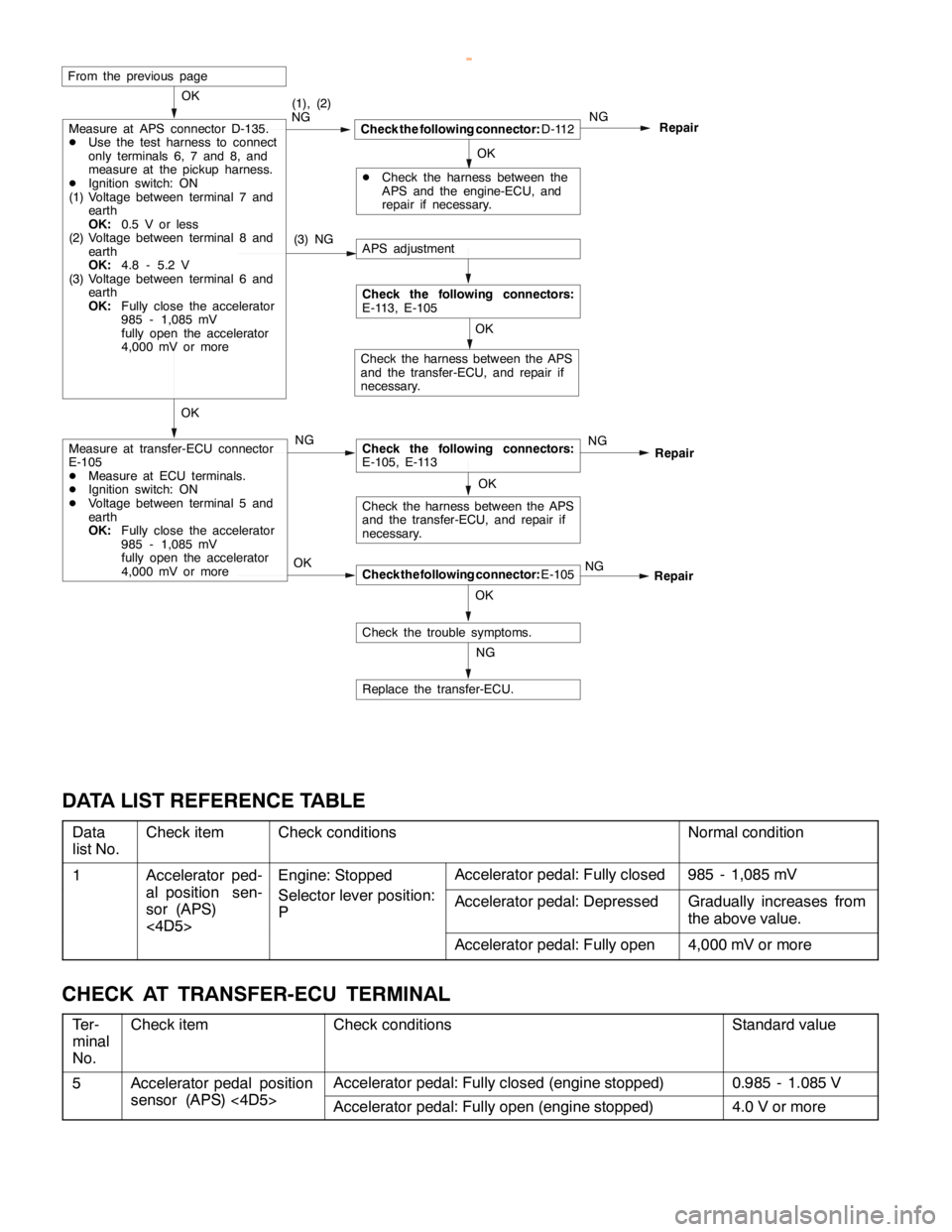
DATA LIST REFERENCE TABLE
Data
list No.Check itemCheck conditionsNormal condition
1Accelerator ped-
alpositionsen
Engine: Stopped
Sllii
Accelerator pedal: Fully closed985 - 1,085 mV
al position sen-
sor (APS)
<4D5>Selector lever position:
PAccelerator pedal: DepressedGradually increases from
the above value.
<4D5>
Accelerator pedal: Fully open4,000 mV or more
CHECK AT TRANSFER-ECU TERMINAL
Ter-
minal
No.Check itemCheck conditionsStandard value
5Accelerator pedal position
(APS)4D5
Accelerator pedal: Fully closed (engine stopped)0.985 - 1.085 Vpp
sensor (APS) <4D5>Accelerator pedal: Fully open (engine stopped)4.0 V or more
www.WorkshopManuals.co.uk
Purchased from www.WorkshopManuals.co.uk
Page 902 of 1839

Page 907 of 1839

Page 913 of 1839

Page 914 of 1839

Page 915 of 1839
