2000 MITSUBISHI MONTERO ECU
[x] Cancel search: ECUPage 643 of 1839
DIESEL FUEL <4D5-stepIII>-Troubleshooting13E-33
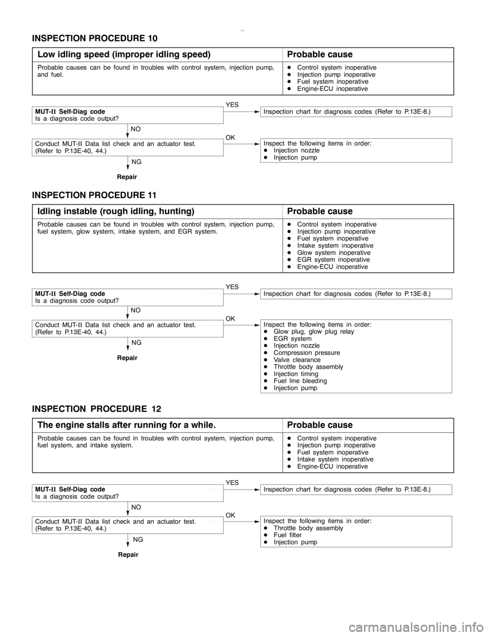
INSPECTION PROCEDURE 10
Low idling speed (improper idling speed)
Probable cause
Probable causes can be found in troubles with control system, injection pump,
and fuel.DControl system inoperative
DInjection pump inoperative
DFuel system inoperative
DEngine-ECU inoperative
NG
Repair
MUT-IISelf-Diag code
Is a diagnosis code output?YESInspection chart for diagnosis codes (Refer to P.13E-8.)
NO
Conduct MUT-IIData list check and an actuator test.
(Refer to P.13E-40, 44.)OKInspect the following items in order:
DInjection nozzle
DInjection pump
INSPECTION PROCEDURE 11
Idling instable (rough idling, hunting)
Probable cause
Probable causes can be found in troubles with control system, injection pump,
fuel system, glow system, intake system, and EGR system.DControl system inoperative
DInjection pump inoperative
DFuel system inoperative
DIntake system inoperative
DGlow system inoperative
DEGR system inoperative
DEngine-ECU inoperative
NG
Repair
MUT-IISelf-Diag code
Is a diagnosis code output?YESInspection chart for diagnosis codes (Refer to P.13E-8.)
NO
Conduct MUT-IIData list check and an actuator test.
(Refer to P.13E-40, 44.)OKInspect the following items in order:
DGlow plug, glow plug relay
DEGR system
DInjection nozzle
DCompression pressure
DValve clearance
DThrottle body assembly
DInjection timing
DFuel line bleeding
DInjection pump
INSPECTION PROCEDURE 12
The engine stalls after running for a while.
Probable cause
Probable causes can be found in troubles with control system, injection pump,
fuel system, and intake system.DControl system inoperative
DInjection pump inoperative
DFuel system inoperative
DIntake system inoperative
DEngine-ECU inoperative
NG
Repair
MUT-IISelf-Diag code
Is a diagnosis code output?YESInspection chart for diagnosis codes (Refer to P.13E-8.)
NO
Conduct MUT-IIData list check and an actuator test.
(Refer to P.13E-40, 44.)OKInspect the following items in order:
DThrottle body assembly
DFuel filter
DInjection pump
www.WorkshopManuals.co.uk
Purchased from www.WorkshopManuals.co.uk
Page 644 of 1839
DIESEL FUEL <4D5-stepIII>-Troubleshooting13E-34
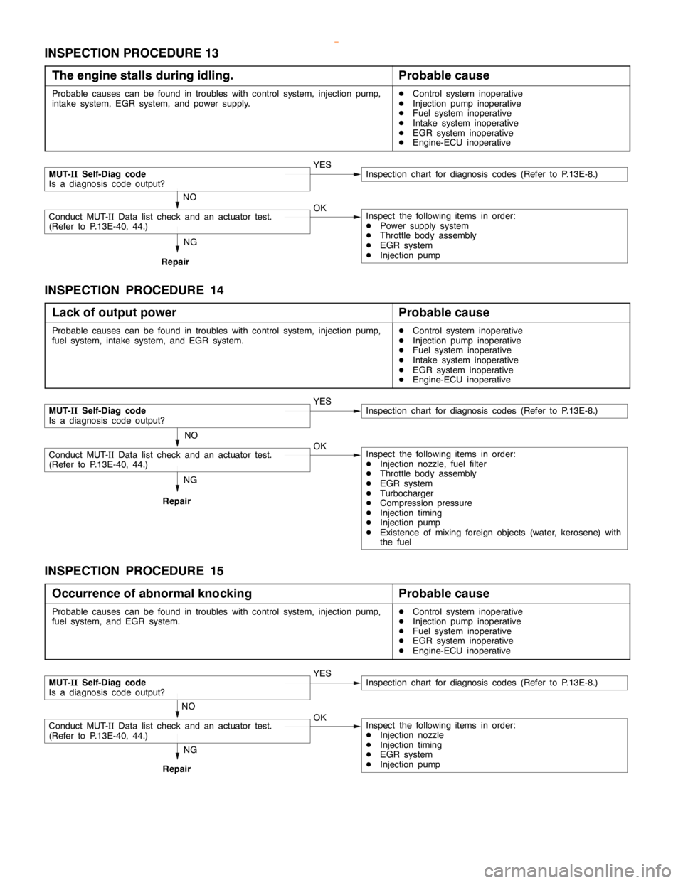
INSPECTION PROCEDURE 13
The engine stalls during idling.
Probable cause
Probable causes can be found in troubles with control system, injection pump,
intake system, EGR system, and power supply.DControl system inoperative
DInjection pump inoperative
DFuel system inoperative
DIntake system inoperative
DEGR system inoperative
DEngine-ECU inoperative
NG
Repair
MUT-IISelf-Diag code
Is a diagnosis code output?YESInspection chart for diagnosis codes (Refer to P.13E-8.)
NO
Conduct MUT-IIData list check and an actuator test.
(Refer to P.13E-40, 44.)OKInspect the following items in order:
DPower supply system
DThrottle body assembly
DEGR system
DInjection pump
INSPECTION PROCEDURE 14
Lack of output power
Probable cause
Probable causes can be found in troubles with control system, injection pump,
fuel system, intake system, and EGR system.DControl system inoperative
DInjection pump inoperative
DFuel system inoperative
DIntake system inoperative
DEGR system inoperative
DEngine-ECU inoperative
NG
Repair
MUT-IISelf-Diag code
Is a diagnosis code output?YESInspection chart for diagnosis codes (Refer to P.13E-8.)
NO
Conduct MUT-IIData list check and an actuator test.
(Refer to P.13E-40, 44.)OKInspect the following items in order:
DInjection nozzle, fuel filter
DThrottle body assembly
DEGR system
DTurbocharger
DCompression pressure
DInjection timing
DInjection pump
DExistence of mixing foreign objects (water, kerosene) with
the fuel
INSPECTION PROCEDURE 15
Occurrence of abnormal knocking
Probable cause
Probable causes can be found in troubles with control system, injection pump,
fuel system, and EGR system.DControl system inoperative
DInjection pump inoperative
DFuel system inoperative
DEGR system inoperative
DEngine-ECU inoperative
NG
Repair
MUT-IISelf-Diag code
Is a diagnosis code output?YESInspection chart for diagnosis codes (Refer to P.13E-8.)
NO
Conduct MUT-IIData list check and an actuator test.
(Refer to P.13E-40, 44.)OKInspect the following items in order:
DInjection nozzle
DInjection timing
DEGR system
DInjection pump
www.WorkshopManuals.co.uk
Purchased from www.WorkshopManuals.co.uk
Page 645 of 1839
DIESEL FUEL <4D5-stepIII>-Troubleshooting13E-35
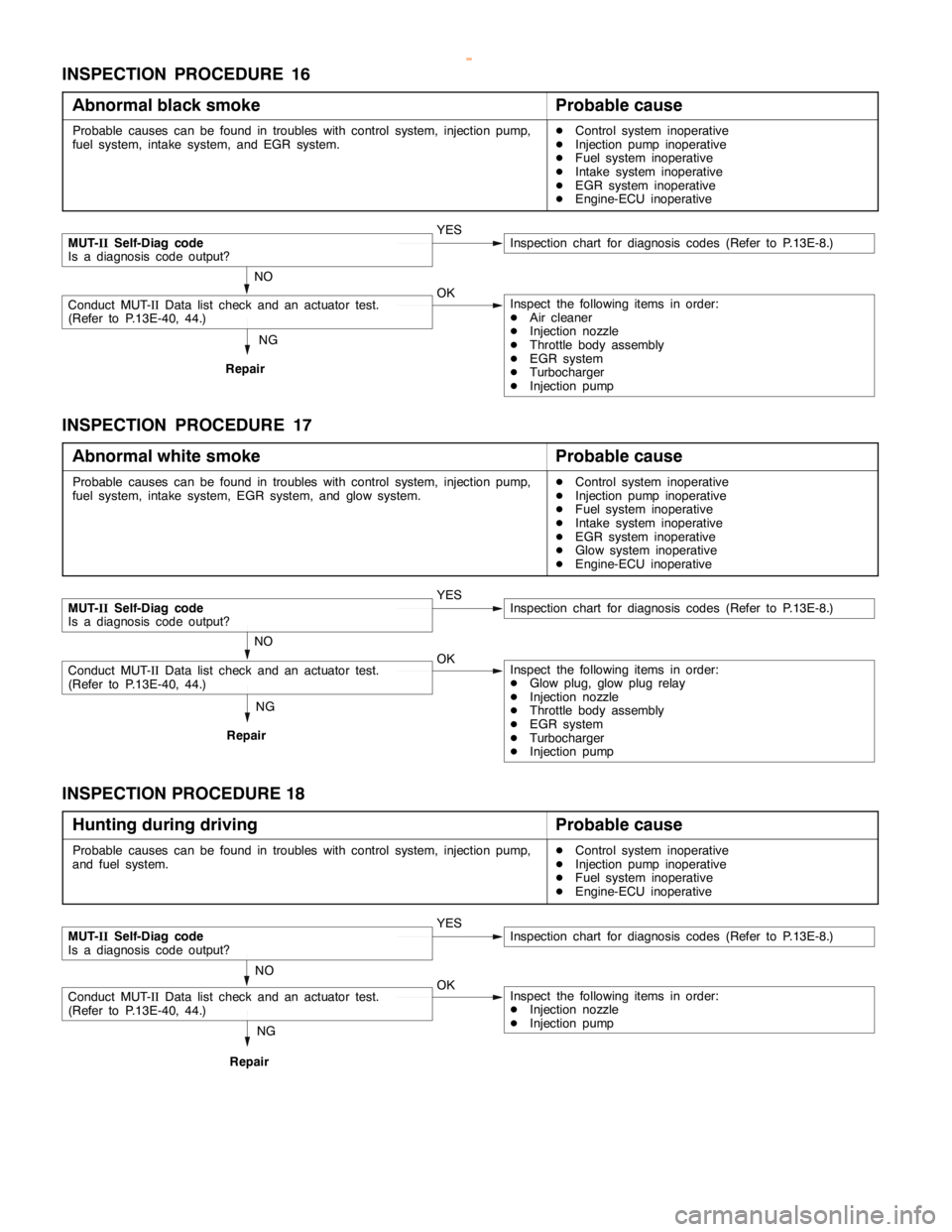
INSPECTION PROCEDURE 16
Abnormal black smoke
Probable cause
Probable causes can be found in troubles with control system, injection pump,
fuel system, intake system, and EGR system.DControl system inoperative
DInjection pump inoperative
DFuel system inoperative
DIntake system inoperative
DEGR system inoperative
DEngine-ECU inoperative
NG
Repair
MUT-IISelf-Diag code
Is a diagnosis code output?YESInspection chart for diagnosis codes (Refer to P.13E-8.)
NO
Conduct MUT-IIData list check and an actuator test.
(Refer to P.13E-40, 44.)OKInspect the following items in order:
DAir cleaner
DInjection nozzle
DThrottle body assembly
DEGR system
DTurbocharger
DInjection pump
INSPECTION PROCEDURE 17
Abnormal white smoke
Probable cause
Probable causes can be found in troubles with control system, injection pump,
fuel system, intake system, EGR system, and glow system.DControl system inoperative
DInjection pump inoperative
DFuel system inoperative
DIntake system inoperative
DEGR system inoperative
DGlow system inoperative
DEngine-ECU inoperative
NG
Repair
MUT-IISelf-Diag code
Is a diagnosis code output?YESInspection chart for diagnosis codes (Refer to P.13E-8.)
NO
Conduct MUT-IIData list check and an actuator test.
(Refer to P.13E-40, 44.)OKInspect the following items in order:
DGlow plug, glow plug relay
DInjection nozzle
DThrottle body assembly
DEGR system
DTurbocharger
DInjection pump
INSPECTION PROCEDURE 18
Hunting during driving
Probable cause
Probable causes can be found in troubles with control system, injection pump,
and fuel system.DControl system inoperative
DInjection pump inoperative
DFuel system inoperative
DEngine-ECU inoperative
NG
Repair
MUT-IISelf-Diag code
Is a diagnosis code output?YESInspection chart for diagnosis codes (Refer to P.13E-8.)
NO
Conduct MUT-IIData list check and an actuator test.
(Refer to P.13E-40, 44.)OKInspect the following items in order:
DInjection nozzle
DInjection pump
www.WorkshopManuals.co.uk
Purchased from www.WorkshopManuals.co.uk
Page 646 of 1839
DIESEL FUEL <4D5-stepIII>-Troubleshooting13E-36
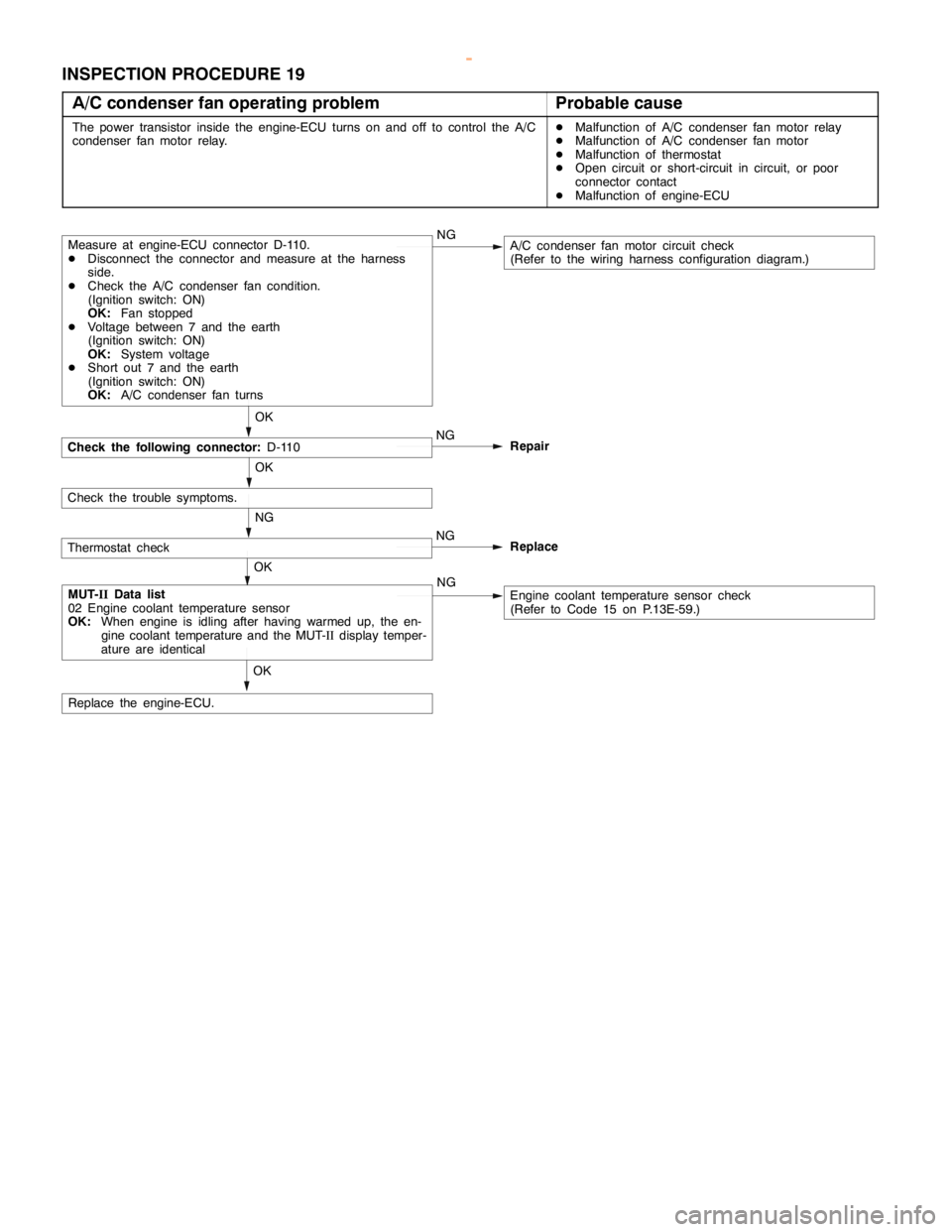
INSPECTION PROCEDURE 19
A/C condenser fan operating problem
Probable cause
The power transistor inside the engine-ECU turns on and off to control the A/C
condenser fan motor relay.DMalfunction of A/C condenser fan motor relay
DMalfunction of A/C condenser fan motor
DMalfunction of thermostat
DOpen circuit or short-circuit in circuit, or poor
connector contact
DMalfunction of engine-ECU
Check the following connector:D-110
OK
Measure at engine-ECU connector D-110.
DDisconnect the connector and measure at the harness
side.
DCheck the A/C condenser fan condition.
(Ignition switch: ON)
OK:Fan stopped
DVoltage between 7 and the earth
(Ignition switch: ON)
OK:System voltage
DShort out 7 and the earth
(Ignition switch: ON)
OK:A/C condenser fan turnsNGA/C condenser fan motor circuit check
(Refer to the wiring harness configuration diagram.)
OK
MUT-IIData list
02 Engine coolant temperature sensor
OK:When engine is idling after having warmed up, the en-
gine coolant temperature and the MUT-IIdisplay temper-
ature are identicalNGEngine coolant temperature sensor check
(Refer to Code 15 on P.13E-59.)
Check the trouble symptoms.OK
Replace the engine-ECU.NG
Repair
Thermostat checkNG
NGReplace
OK
www.WorkshopManuals.co.uk
Purchased from www.WorkshopManuals.co.uk
Page 647 of 1839
DIESEL FUEL <4D5-stepIII>-Troubleshooting13E-37
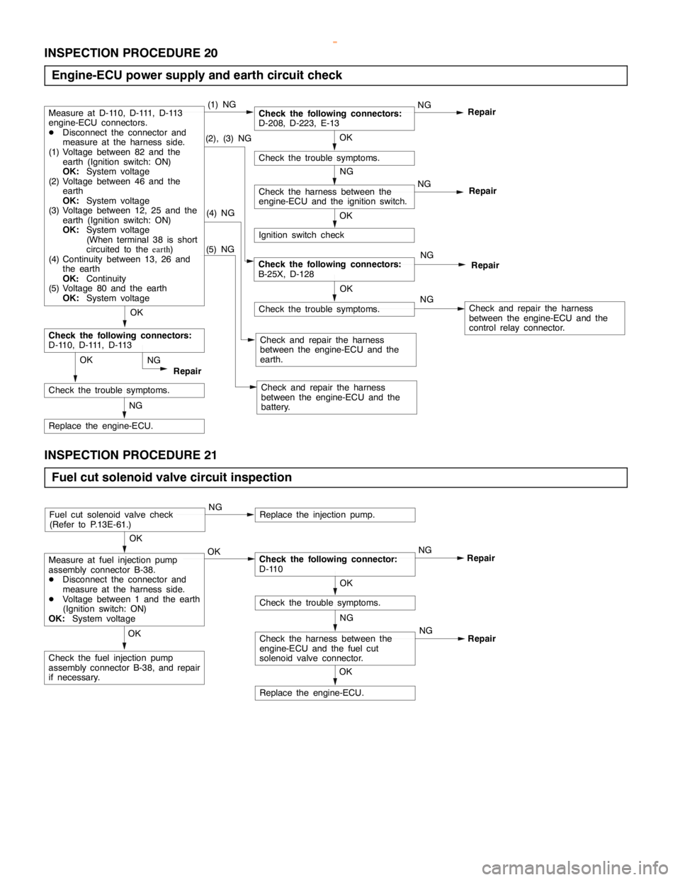
INSPECTION PROCEDURE 20
Engine-ECU power supply and earth circuit check
(5) NG
Check the trouble symptoms.
NG
Repair
(2), (3) NGOK
Check the trouble symptoms.
OK
NG
Check the harness between the
engine-ECU and the ignition switch.
Ignition switch check
(4) NG
Check and repair the harness
between the engine-ECU and the
earth.
OK
Check the following connectors:
D-110, D-111, D-113
NG
Replace the engine-ECU.
OK
Check the trouble symptoms.Repair NG
NG
RepairCheck the following connectors:
B-25X, D-128
NG
Check and repair the harness
between the engine-ECU and the
control relay connector.
Check and repair the harness
between the engine-ECU and the
battery.
Check the following connectors:
D-208, D-223, E-13NG
RepairMeasure at D-110, D-111, D-113
engine-ECU connectors.
DDisconnect the connector and
measure at the harness side.
(1) Voltage between 82 and the
earth (Ignition switch: ON)
OK:System voltage
(2) Voltage between 46 and the
earth
OK:System voltage
(3) Voltage between 12, 25 and the
earth (Ignition switch: ON)
OK:System voltage
(When terminal 38 is short
circuited to theearth)
(4) Continuity between 13, 26 and
the earth
OK:Continuity
(5) Voltage 80 and the earth
OK:System voltage(1) NG
OK
INSPECTION PROCEDURE 21
Fuel cut solenoid valve circuit inspection
NG
Check the harness between the
engine-ECU and the fuel cut
solenoid valve connector.
OK
Replace the engine-ECU.
OK
Check the fuel injection pump
assembly connector B-38, and repair
if necessary.
OK
Check the trouble symptoms.
OK
Measure at fuel injection pump
assembly connector B-38.
DDisconnect the connector and
measure at the harness side.
DVoltage between 1 and the earth
(Ignition switch: ON)
OK:System voltageOKCheck the following connector:
D-110NG
Repair
Fuel cut solenoid valve check
(Refer to P.13E-61.)NGReplace the injection pump.
NG
Repair
www.WorkshopManuals.co.uk
Purchased from www.WorkshopManuals.co.uk
Page 648 of 1839
DIESEL FUEL <4D5-stepIII>-Troubleshooting13E-38
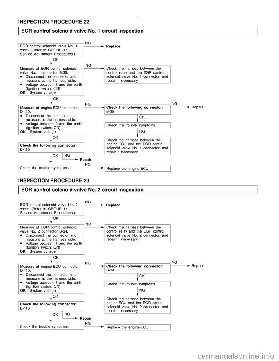
INSPECTION PROCEDURE 22
EGR control solenoid valve No. 1 circuit inspection
NG
Check the harness between the
engine-ECU and the EGR control
solenoid valve No. 1 connector, and
repair if necessary.
OK
Check the trouble symptoms.
OK
Measure at EGR control solenoid
valve No. 1 connector B-35.
DDisconnect the connector and
measure at the harness side.
DVoltage between 1 and the earth
(Ignition switch: ON)
OK:System voltage
NG
Check the following connector:
B-35NG
Repair NG
Check the harness between the
control relay and the EGR control
solenoid valve No. 1 connector, and
repair if necessary.
EGR control solenoid valve No. 1
check (Refer to GROUP 17 -
Service Adjustment Procedures.)NG
Replace
OK
Measure at engine-ECU connector
D-110.
DDisconnect the connector and
measure at the harness side.
DVoltage between 9 and the earth
(Ignition switch: ON)
OK:System voltage
NG
Replace the engine-ECU. NGCheck the trouble symptoms.OK
Repair
Check the following connector:
D-110OK
INSPECTION PROCEDURE 23
EGR control solenoid valve No. 2 circuit inspection
NG
Check the harness between the
engine-ECU and the EGR control
solenoid valve No. 2 connector, and
repair if necessary.
OK
Check the trouble symptoms.
OK
Measure at EGR control solenoid
valve No. 2 connector B-34.
DDisconnect the connector and
measure at the harness side.
DVoltage between 1 and the earth
(Ignition switch: ON)
OK:System voltage
NG
Check the following connector:
B-34NG
Repair NG
Check the harness between the
control relay and the EGR control
solenoid valve No. 2 connector, and
repair if necessary.
EGR control solenoid valve No. 2
check (Refer to GROUP 17 -
Service Adjustment Procedures.)NG
Replace
OK
Measure at engine-ECU connector
D-110.
DDisconnect the connector and
measure at the harness side.
DVoltage between 5 and the earth
(Ignition switch: ON)
OK:System voltage
NG
Replace the engine-ECU. NGCheck the trouble symptoms.OK
Repair
Check the following connector:
D-110OK
www.WorkshopManuals.co.uk
Purchased from www.WorkshopManuals.co.uk
Page 649 of 1839
DIESEL FUEL <4D5-stepIII>-Troubleshooting13E-39
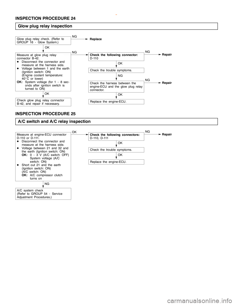
INSPECTION PROCEDURE 24
Glow plug relay inspection
NG
Replace the engine-ECU.
OK
Check the trouble symptoms.
OK
Measure at glow plug relay
connector B-42.
DDisconnect the connector and
measure at the harness side.
DVoltage between 1 and the earth
(Ignition switch: ON)
(Engine coolant temperature:
40_C or lower)
OK:System voltage (for 1 - 8 sec-
onds after ignition switch is
turned to ON)NGCheck the following connector:
D-110NG
Repair
Glow plug relay check. (Refer to
GROUP 16 - Glow System.)NG
Replace
Check glow plug relay connector
B-42, and repair if necessary.OK
OK
Check the harness between the
engine-ECU and the glow plug relay
connector.NG
Repair
INSPECTION PROCEDURE 25
A/C switch and A/C relay inspection
Replace the engine-ECU.
OK
Check the trouble symptoms.
Measure at engine-ECU connector
D-110 or D-111.
DDisconnect the connector and
measure at the harness side.
DVoltage between 21 and 32 and
the earth (Ignition switch: ON)
OK:0 - 3 V (A/C switch: OFF)
System voltage (A/C
switch: ON)
DShort out 21 and the earth
(Ignition switch: ON)
(A/C switch: ON)
OK:A/C compressor clutch
turns onOKCheck the following connectors:
D-110, D-111NG
Repair
A/C system check
(Refer to GROUP 54 - Service
Adjustment Procedures.)NGOK
www.WorkshopManuals.co.uk
Purchased from www.WorkshopManuals.co.uk
Page 654 of 1839

DIESEL FUEL <4D5-stepIII>-Troubleshooting13E-44
ACTUATOR TEST TABLE
Item
No.Check itemDrive Con-
tentsInspection
conditionsValue to be determined
as normalCode No.
or inspec-
tion proce-
dure No.Reference
page
02Glow plug relayTurning the
relayfrom
Ignition switch:
ON
Battery charge is
energizedtotheglow
Procedure
No24
13E-39
relayfrom
OFF to ON or
fromONto
ONenergizedtotheglow
plug when the glow
plugrelayisON
No.24
fromONto
OFFplug relayisON.
03A/C compressor
relay
Turning the
relayfrom
Ignition switch:
ON
The A/C compressor
clutchmakesan
Procedure
No25
13E-39
relayrelayfrom
OFF to ON or
fromONto
ONclutchmakes an
audible sound.No.25
fromONto
OFF
11Timing control
valveTurn the
timing control
valve to ONDIgnition
switch: ON
DEngine:
Idlin
g
Makes an audible
soundCode No.
4313E-21
12Turn the
timing control
valve to OFF
Idling
DTimer piston
position
sensor:
Normal
15Glow lampTurn the glow
lamp on or offIgnition switch:
ONThe glow lamp turns
on.––
16Warning lampTurn the
warning lamp
on or offIgnition switch:
ONThe warning lamp
turns on.Procedure
No. 3, 413E-30
22Condenser fan
relayTurning the
relay from
OFF to ON or
from ON to
OFFIgnition switch:
ONThe condenser fan
rotates.Procedure
No. 1913E-36
23Throttle solenoid
valveTurn the
solenoid
valve from
OFF to ON or
from ON to
OFFDIgnition
switch: ON
DVehicle
speed:
0 km/h
DEngine
speed:
1,000 r/min
or lowerMakes an audible
soundCode No.
4113E-20
25GE actuatorTurn the GE
actuator to
ONDIgnition
switch: ON
DEngine
speed:
0 r/min orMeasure the wave
pattern between
engine-ECU connec-
tor terminals No. 1
and No. 15 using anCode No.
4813E-23
26Turn the GE
actuator to
OFF
0r/minor
lower
DControl
sleeve posi-
tion sensor:
Normal
andNo.15usingan
analyzer and check
the change in the duty
ratio.
www.WorkshopManuals.co.uk
Purchased from www.WorkshopManuals.co.uk