2000 DODGE NEON brakes
[x] Cancel search: brakesPage 132 of 1285
(22) Install the center console and its mounting
screws.
(23) Remove the blocks from the tires and wheels.
PARKING BRAKE SHOES (REAR DISC BRAKE)
NOTE: Before proceeding with this procedure,
review SERVICE WARNINGS AND CAUTIONS at the
beginning of REMOVAL AND INSTALLATION in this
section.
REMOVAL
(1) Raise the vehicle. Refer to HOISTING in the
LUBRICATION AND MAINTENANCE group for the
proper lifting procedure.
(2) Remove the rear tire and wheel assembly.
(3) Remove the rear disc brake caliper assembly
from the brake rotor and store it out of the way.
Refer to DISC BRAKE SHOES (REAR) in this
REMOVAL AND INSTALLATION section of this ser-
vice manual group.
(4) Remove rear brake rotor.
(5) Remove the dust cap from the rear hub and
bearing.
(6) Remove the rear hub and bearing assembly
retaining nut and washer.
(7) Remove the rear hub and bearing assembly
from the rear spindle.
(8) Remove the rear brake shoe assembly hold-
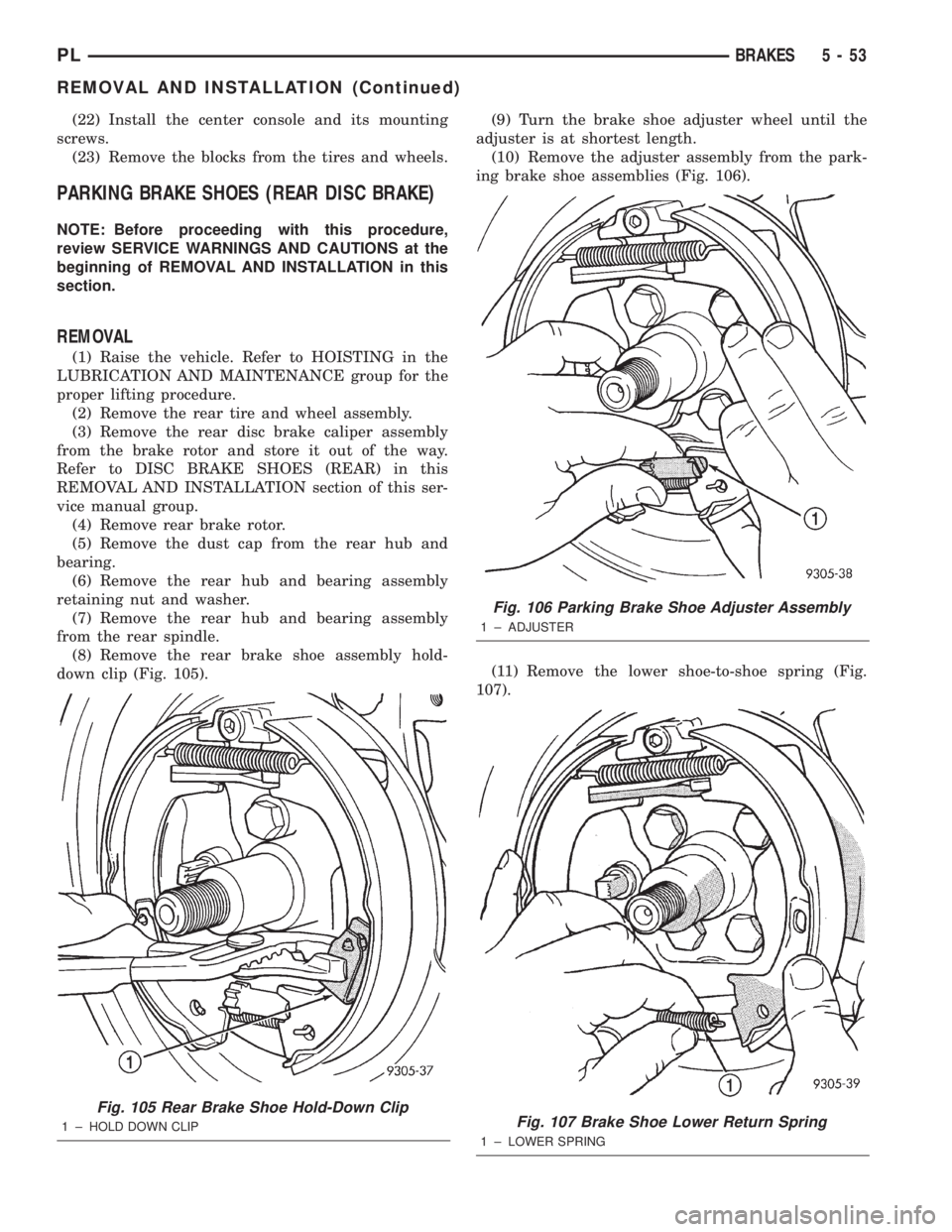
down clip (Fig. 105).(9) Turn the brake shoe adjuster wheel until the
adjuster is at shortest length.
(10) Remove the adjuster assembly from the park-
ing brake shoe assemblies (Fig. 106).
(11) Remove the lower shoe-to-shoe spring (Fig.
107).
Fig. 105 Rear Brake Shoe Hold-Down Clip
1 ± HOLD DOWN CLIP
Fig. 106 Parking Brake Shoe Adjuster Assembly
1 ± ADJUSTER
Fig. 107 Brake Shoe Lower Return Spring
1 ± LOWER SPRING
PLBRAKES 5 - 53
REMOVAL AND INSTALLATION (Continued)
Page 133 of 1285
(12) Pull the rear brake shoe away from anchor.
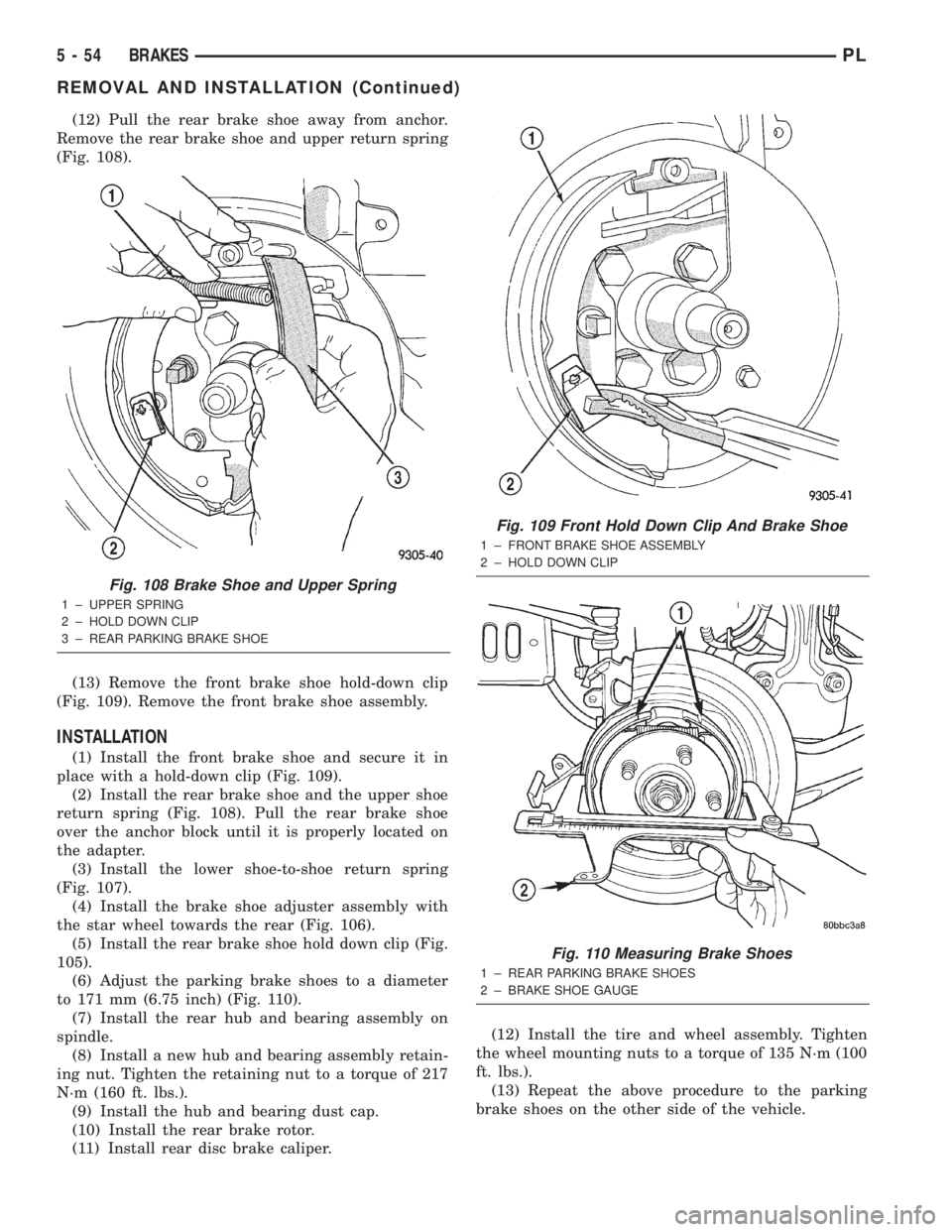
Remove the rear brake shoe and upper return spring
(Fig. 108).
(13) Remove the front brake shoe hold-down clip
(Fig. 109). Remove the front brake shoe assembly.
INSTALLATION
(1) Install the front brake shoe and secure it in
place with a hold-down clip (Fig. 109).
(2) Install the rear brake shoe and the upper shoe
return spring (Fig. 108). Pull the rear brake shoe
over the anchor block until it is properly located on
the adapter.
(3) Install the lower shoe-to-shoe return spring
(Fig. 107).
(4) Install the brake shoe adjuster assembly with
the star wheel towards the rear (Fig. 106).
(5) Install the rear brake shoe hold down clip (Fig.
105).
(6) Adjust the parking brake shoes to a diameter
to 171 mm (6.75 inch) (Fig. 110).
(7) Install the rear hub and bearing assembly on
spindle.
(8) Install a new hub and bearing assembly retain-
ing nut. Tighten the retaining nut to a torque of 217
N´m (160 ft. lbs.).
(9) Install the hub and bearing dust cap.
(10) Install the rear brake rotor.
(11) Install rear disc brake caliper.(12) Install the tire and wheel assembly. Tighten
the wheel mounting nuts to a torque of 135 N´m (100
ft. lbs.).
(13) Repeat the above procedure to the parking
brake shoes on the other side of the vehicle.
Fig. 108 Brake Shoe and Upper Spring
1 ± UPPER SPRING
2 ± HOLD DOWN CLIP
3 ± REAR PARKING BRAKE SHOE
Fig. 109 Front Hold Down Clip And Brake Shoe
1 ± FRONT BRAKE SHOE ASSEMBLY
2 ± HOLD DOWN CLIP
Fig. 110 Measuring Brake Shoes
1 ± REAR PARKING BRAKE SHOES
2 ± BRAKE SHOE GAUGE
5 - 54 BRAKESPL
REMOVAL AND INSTALLATION (Continued)
Page 134 of 1285
(14) Adjust the parking brake shoes as necessary.
Refer to ADJUSTMENTS in this section of this ser-
vice manual group.
(15) Lower the vehicle.
DISASSEMBLY AND ASSEMBLY
DISC BRAKE CALIPER (FRONT AND REAR)
Before disassembling the brake caliper, clean and
inspect it. Refer to CLEANING AND INSPECTION
in this section of this service manual group.
CALIPER GUIDE PIN BUSHING
REMOVAL
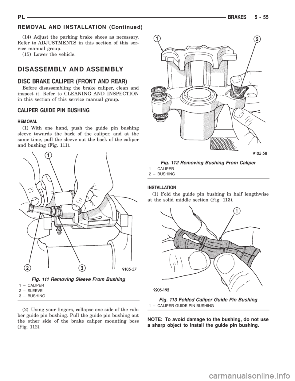
(1) With one hand, push the guide pin bushing
sleeve towards the back of the caliper, and at the
same time, pull the sleeve out the back of the caliper
and bushing (Fig. 111).
(2) Using your fingers, collapse one side of the rub-
ber guide pin bushing. Pull the guide pin bushing out
the other side of the brake caliper mounting boss
(Fig. 112).INSTALLATION
(1) Fold the guide pin bushing in half lengthwise
at the solid middle section (Fig. 113).
NOTE: To avoid damage to the bushing, do not use
a sharp object to install the guide pin bushing.
Fig. 111 Removing Sleeve From Bushing
1 ± CALIPER
2 ± SLEEVE
3 ± BUSHING
Fig. 112 Removing Bushing From Caliper
1 ± CALIPER
2 ± BUSHING
Fig. 113 Folded Caliper Guide Pin Bushing
1 ± CALIPER GUIDE PIN BUSHING
PLBRAKES 5 - 55
REMOVAL AND INSTALLATION (Continued)
Page 135 of 1285
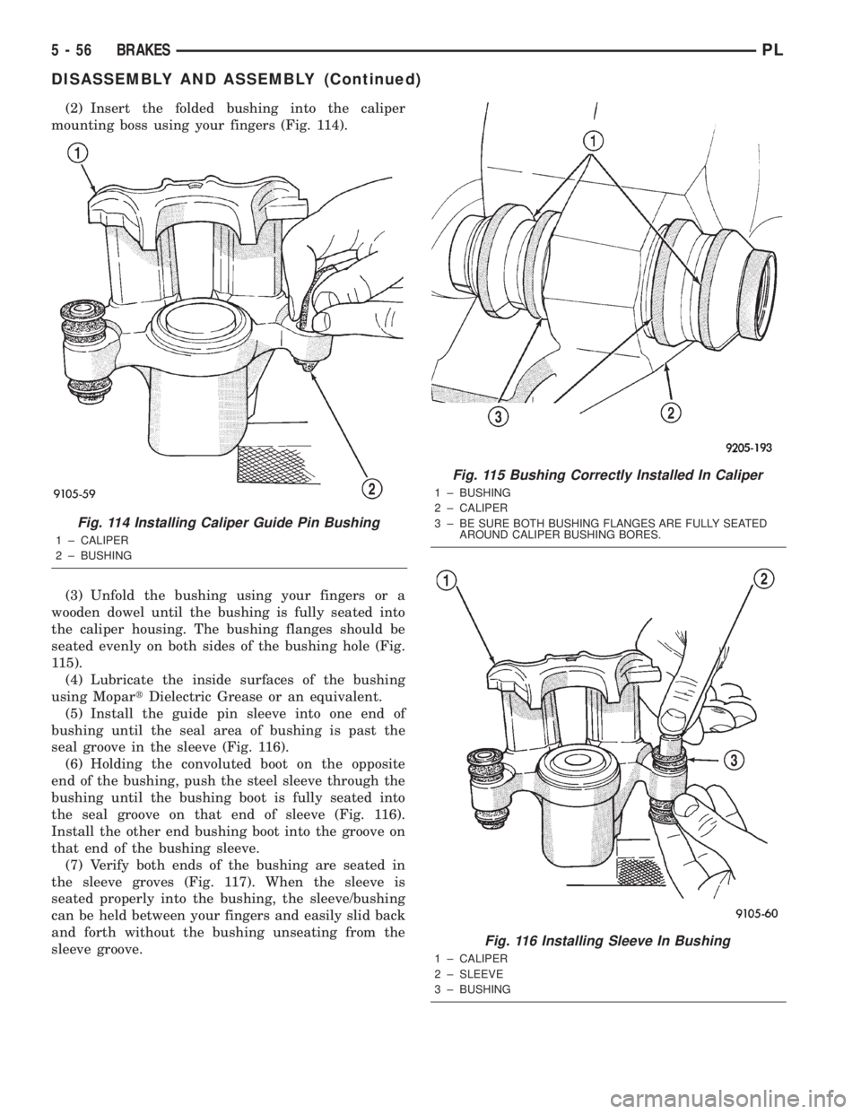
(2) Insert the folded bushing into the caliper
mounting boss using your fingers (Fig. 114).
(3) Unfold the bushing using your fingers or a
wooden dowel until the bushing is fully seated into
the caliper housing. The bushing flanges should be
seated evenly on both sides of the bushing hole (Fig.
115).
(4) Lubricate the inside surfaces of the bushing
using MopartDielectric Grease or an equivalent.
(5) Install the guide pin sleeve into one end of
bushing until the seal area of bushing is past the
seal groove in the sleeve (Fig. 116).
(6) Holding the convoluted boot on the opposite
end of the bushing, push the steel sleeve through the
bushing until the bushing boot is fully seated into
the seal groove on that end of sleeve (Fig. 116).
Install the other end bushing boot into the groove on
that end of the bushing sleeve.
(7) Verify both ends of the bushing are seated in
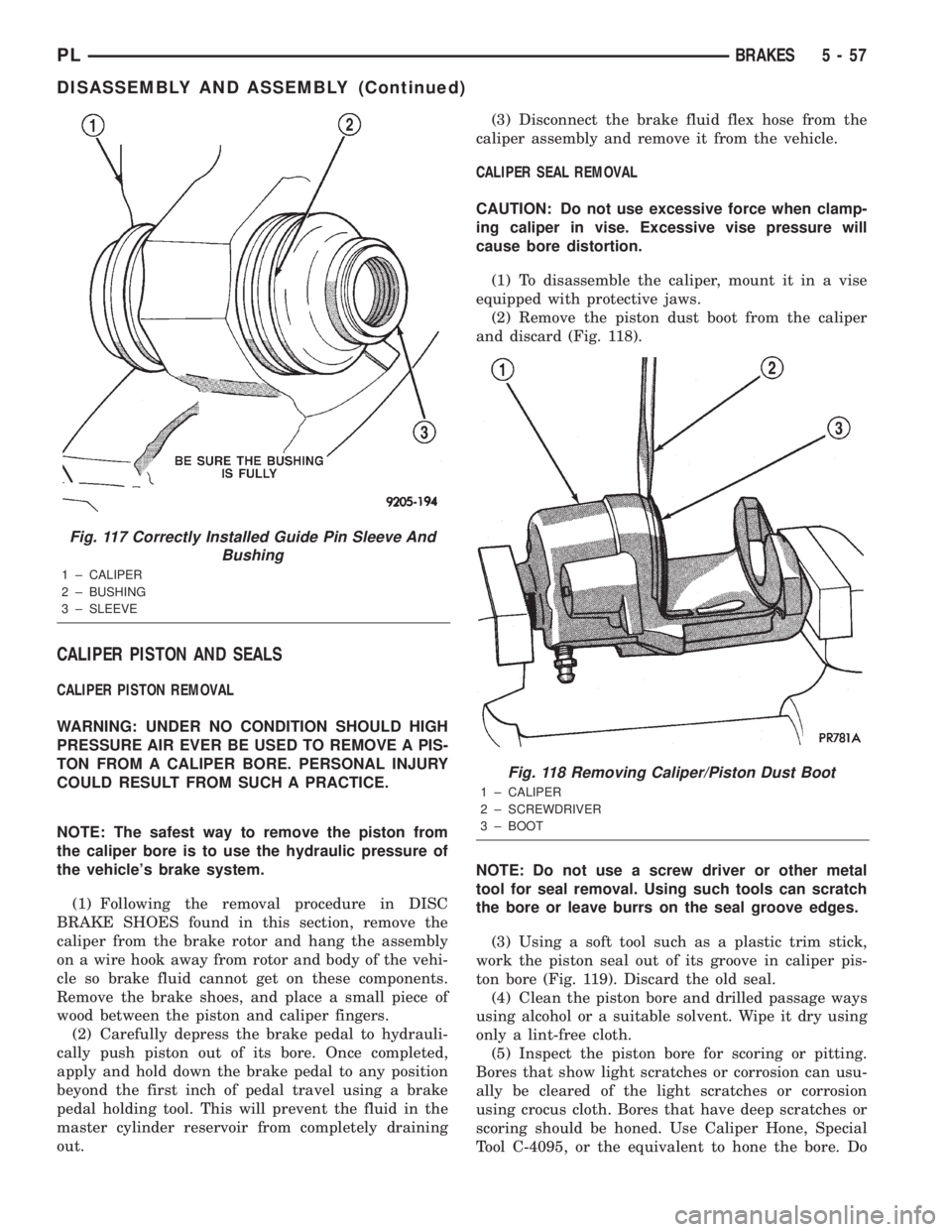
the sleeve groves (Fig. 117). When the sleeve is
seated properly into the bushing, the sleeve/bushing
can be held between your fingers and easily slid back
and forth without the bushing unseating from the
sleeve groove.
Fig. 114 Installing Caliper Guide Pin Bushing
1 ± CALIPER
2 ± BUSHING
Fig. 115 Bushing Correctly Installed In Caliper
1 ± BUSHING
2 ± CALIPER
3 ± BE SURE BOTH BUSHING FLANGES ARE FULLY SEATED
AROUND CALIPER BUSHING BORES.
Fig. 116 Installing Sleeve In Bushing
1 ± CALIPER
2 ± SLEEVE
3 ± BUSHING
5 - 56 BRAKESPL
DISASSEMBLY AND ASSEMBLY (Continued)
Page 136 of 1285
CALIPER PISTON AND SEALS
CALIPER PISTON REMOVAL
WARNING: UNDER NO CONDITION SHOULD HIGH
PRESSURE AIR EVER BE USED TO REMOVE A PIS-
TON FROM A CALIPER BORE. PERSONAL INJURY
COULD RESULT FROM SUCH A PRACTICE.
NOTE: The safest way to remove the piston from
the caliper bore is to use the hydraulic pressure of
the vehicle's brake system.
(1) Following the removal procedure in DISC
BRAKE SHOES found in this section, remove the
caliper from the brake rotor and hang the assembly
on a wire hook away from rotor and body of the vehi-
cle so brake fluid cannot get on these components.
Remove the brake shoes, and place a small piece of
wood between the piston and caliper fingers.
(2) Carefully depress the brake pedal to hydrauli-
cally push piston out of its bore. Once completed,
apply and hold down the brake pedal to any position
beyond the first inch of pedal travel using a brake
pedal holding tool. This will prevent the fluid in the
master cylinder reservoir from completely draining
out.(3) Disconnect the brake fluid flex hose from the
caliper assembly and remove it from the vehicle.
CALIPER SEAL REMOVAL
CAUTION: Do not use excessive force when clamp-
ing caliper in vise. Excessive vise pressure will
cause bore distortion.
(1) To disassemble the caliper, mount it in a vise
equipped with protective jaws.
(2) Remove the piston dust boot from the caliper
and discard (Fig. 118).
NOTE: Do not use a screw driver or other metal
tool for seal removal. Using such tools can scratch
the bore or leave burrs on the seal groove edges.
(3) Using a soft tool such as a plastic trim stick,
work the piston seal out of its groove in caliper pis-
ton bore (Fig. 119). Discard the old seal.
(4) Clean the piston bore and drilled passage ways
using alcohol or a suitable solvent. Wipe it dry using
only a lint-free cloth.
(5) Inspect the piston bore for scoring or pitting.
Bores that show light scratches or corrosion can usu-
ally be cleared of the light scratches or corrosion
using crocus cloth. Bores that have deep scratches or
scoring should be honed. Use Caliper Hone, Special
Tool C-4095, or the equivalent to hone the bore. Do
Fig. 117 Correctly Installed Guide Pin Sleeve And
Bushing
1 ± CALIPER
2 ± BUSHING
3 ± SLEEVE
Fig. 118 Removing Caliper/Piston Dust Boot
1 ± CALIPER
2 ± SCREWDRIVER
3 ± BOOT
PLBRAKES 5 - 57
DISASSEMBLY AND ASSEMBLY (Continued)
Page 137 of 1285
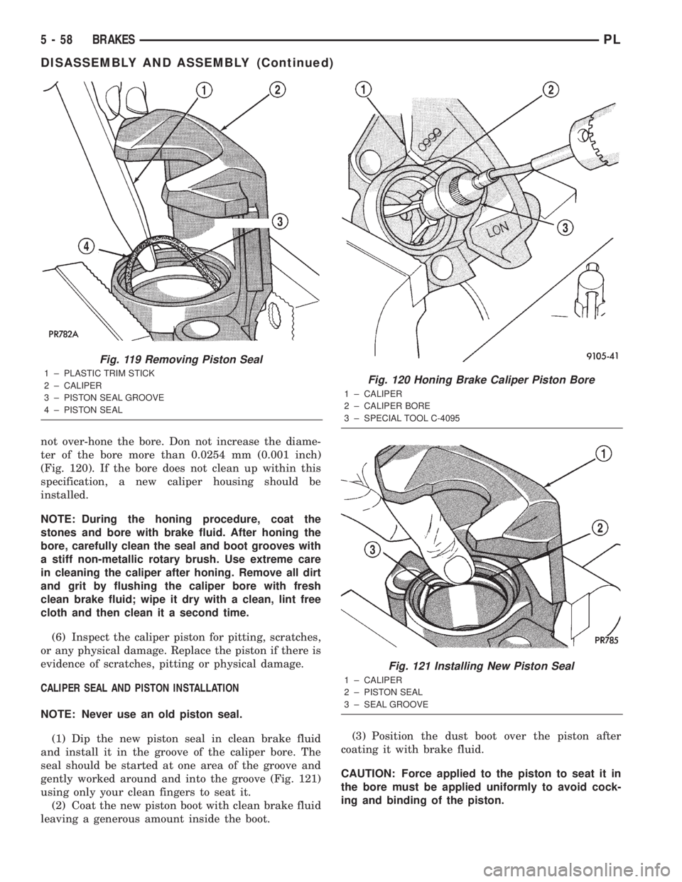
not over-hone the bore. Don not increase the diame-
ter of the bore more than 0.0254 mm (0.001 inch)
(Fig. 120). If the bore does not clean up within this
specification, a new caliper housing should be
installed.
NOTE: During the honing procedure, coat the
stones and bore with brake fluid. After honing the
bore, carefully clean the seal and boot grooves with
a stiff non-metallic rotary brush. Use extreme care
in cleaning the caliper after honing. Remove all dirt
and grit by flushing the caliper bore with fresh
clean brake fluid; wipe it dry with a clean, lint free
cloth and then clean it a second time.
(6) Inspect the caliper piston for pitting, scratches,
or any physical damage. Replace the piston if there is
evidence of scratches, pitting or physical damage.
CALIPER SEAL AND PISTON INSTALLATION
NOTE: Never use an old piston seal.
(1) Dip the new piston seal in clean brake fluid
and install it in the groove of the caliper bore. The
seal should be started at one area of the groove and
gently worked around and into the groove (Fig. 121)
using only your clean fingers to seat it.
(2) Coat the new piston boot with clean brake fluid
leaving a generous amount inside the boot.(3) Position the dust boot over the piston after
coating it with brake fluid.
CAUTION: Force applied to the piston to seat it in
the bore must be applied uniformly to avoid cock-
ing and binding of the piston.
Fig. 119 Removing Piston Seal
1 ± PLASTIC TRIM STICK
2 ± CALIPER
3 ± PISTON SEAL GROOVE
4 ± PISTON SEALFig. 120 Honing Brake Caliper Piston Bore
1 ± CALIPER
2 ± CALIPER BORE
3 ± SPECIAL TOOL C-4095
Fig. 121 Installing New Piston Seal
1 ± CALIPER
2 ± PISTON SEAL
3 ± SEAL GROOVE
5 - 58 BRAKESPL
DISASSEMBLY AND ASSEMBLY (Continued)
Page 138 of 1285
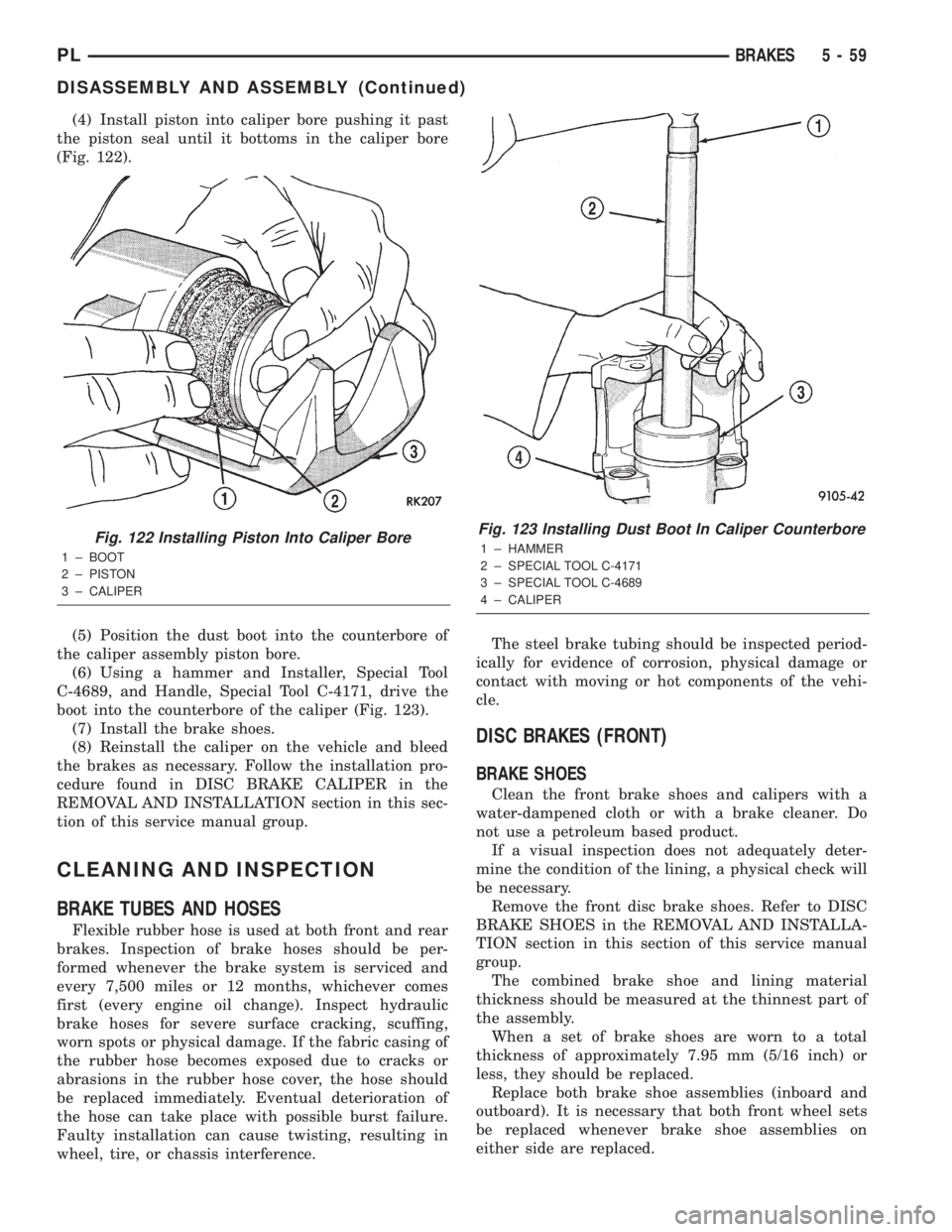
(4) Install piston into caliper bore pushing it past
the piston seal until it bottoms in the caliper bore
(Fig. 122).
(5) Position the dust boot into the counterbore of
the caliper assembly piston bore.
(6) Using a hammer and Installer, Special Tool
C-4689, and Handle, Special Tool C-4171, drive the
boot into the counterbore of the caliper (Fig. 123).
(7) Install the brake shoes.
(8) Reinstall the caliper on the vehicle and bleed
the brakes as necessary. Follow the installation pro-
cedure found in DISC BRAKE CALIPER in the
REMOVAL AND INSTALLATION section in this sec-
tion of this service manual group.
CLEANING AND INSPECTION
BRAKE TUBES AND HOSES
Flexible rubber hose is used at both front and rear
brakes. Inspection of brake hoses should be per-
formed whenever the brake system is serviced and
every 7,500 miles or 12 months, whichever comes
first (every engine oil change). Inspect hydraulic
brake hoses for severe surface cracking, scuffing,
worn spots or physical damage. If the fabric casing of
the rubber hose becomes exposed due to cracks or
abrasions in the rubber hose cover, the hose should
be replaced immediately. Eventual deterioration of
the hose can take place with possible burst failure.
Faulty installation can cause twisting, resulting in
wheel, tire, or chassis interference.The steel brake tubing should be inspected period-
ically for evidence of corrosion, physical damage or
contact with moving or hot components of the vehi-
cle.
DISC BRAKES (FRONT)
BRAKE SHOES
Clean the front brake shoes and calipers with a
water-dampened cloth or with a brake cleaner. Do
not use a petroleum based product.
If a visual inspection does not adequately deter-
mine the condition of the lining, a physical check will
be necessary.
Remove the front disc brake shoes. Refer to DISC
BRAKE SHOES in the REMOVAL AND INSTALLA-
TION section in this section of this service manual
group.
The combined brake shoe and lining material
thickness should be measured at the thinnest part of
the assembly.
When a set of brake shoes are worn to a total
thickness of approximately 7.95 mm (5/16 inch) or
less, they should be replaced.
Replace both brake shoe assemblies (inboard and
outboard). It is necessary that both front wheel sets
be replaced whenever brake shoe assemblies on
either side are replaced.
Fig. 122 Installing Piston Into Caliper Bore
1 ± BOOT
2 ± PISTON
3 ± CALIPER
Fig. 123 Installing Dust Boot In Caliper Counterbore
1 ± HAMMER
2 ± SPECIAL TOOL C-4171
3 ± SPECIAL TOOL C-4689
4 ± CALIPER
PLBRAKES 5 - 59
DISASSEMBLY AND ASSEMBLY (Continued)
Page 139 of 1285
If the brake shoe assemblies do not require
replacement, reinstall the assemblies making sure
each brake shoe is returned to the original position.
Refer to DISC BRAKE SHOES in the REMOVAL
AND INSTALLATION section in this section of this
service manual group.
CALIPER INSPECTION
Check for brake fluid leaks in and around the boot
area. Check for any ruptures, brittleness or damage
to the piston dust boot. If the boot is damaged, or a
fluid leak is visible, disassemble the caliper assembly
and install a new seal and boot, and a piston if it is
scored. Refer to DISC BRAKE CALIPER in the DIS-
ASSEMBLY AND ASSEMBLY section in this section
of this service manual group.
Check the guide pin dust boots to determine if they
are in good condition. Replace if they are damaged,
dry, or found to be brittle. Refer to DISC BRAKE
CALIPER in the DISASSEMBLY AND ASSEMBLY
section in this section of this service manual group.
DISC BRAKES (REAR)
BRAKE SHOES
Clean the rear brake shoes and calipers with a
water-dampened cloth or with a brake cleaner. Do
not use a petroleum based product.
If a visual inspection does not adequately deter-
mine the condition of the lining, a physical check will
be necessary.
Remove the rear disc brake shoes. Refer to DISC
BRAKE SHOES in the REMOVAL AND INSTALLA-
TION section in this section of this service manual
group.
The combined brake shoe and lining material
thickness should be measured at the thinnest part of
the assembly.
When a set of brake shoes are worn to a total
thickness of approximately 7.0 mm (9/32 inch) or
less, they should be replaced.
Replace both brake shoe assemblies (inboard and
outboard). It is necessary that both front wheel sets
be replaced whenever brake shoe assemblies on
either side are replaced.
If the brake shoe assemblies do not require
replacement, reinstall the assemblies making sure
each brake shoe is returned to the original position.
Refer to DISC BRAKE SHOES in the REMOVAL
AND INSTALLATION section in this section of this
service manual group.
CALIPER INSPECTION
Check for brake fluid leaks in and around the boot
area. Check for any ruptures, brittleness or damage
to the piston dust boot. If the boot is damaged, or afluid leak is visible, disassemble the caliper assembly
and install a new seal and boot, and a piston if it is
scored. Refer to DISC BRAKE CALIPER in the DIS-
ASSEMBLY AND ASSEMBLY section in this section
of this service manual group.
Check the guide pin dust boots to determine if they
are in good condition. Replace if they are damaged,
dry, or found to be brittle. Refer to DISC BRAKE
CALIPER in the DISASSEMBLY AND ASSEMBLY
section in this section of this service manual group.
DRUM BRAKES (REAR)
BRAKE SHOES
Clean the rear brake shoes and springs with a
water-dampened cloth or with a brake cleaner. Do
not use a petroleum based product.
Rear brake shoe lining should show contact across
the entire width of the lining and also from the heel
to the toe of the lining. Replace the shoes if noted
otherwise.
Brake shoes with lack of contact at the toe or heel
of the brake shoe lining may be improperly ground.
Clean and inspect the brake support plate and
shoe adjuster screw. Apply a thin coat of Mopart
Multi-Purpose Lubricant or equivalent to the threads
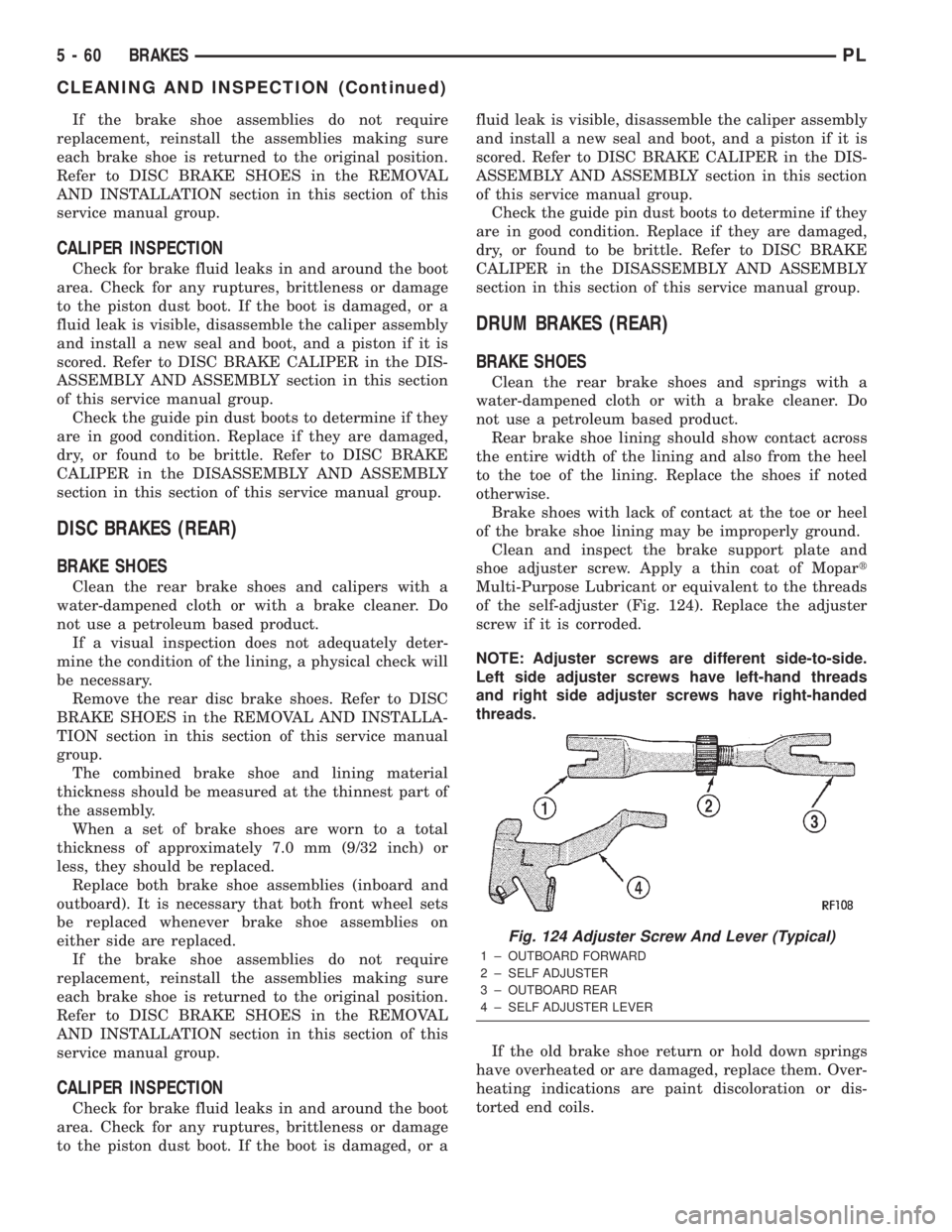
of the self-adjuster (Fig. 124). Replace the adjuster
screw if it is corroded.
NOTE: Adjuster screws are different side-to-side.
Left side adjuster screws have left-hand threads
and right side adjuster screws have right-handed
threads.
If the old brake shoe return or hold down springs
have overheated or are damaged, replace them. Over-
heating indications are paint discoloration or dis-
torted end coils.
Fig. 124 Adjuster Screw And Lever (Typical)
1 ± OUTBOARD FORWARD
2 ± SELF ADJUSTER
3 ± OUTBOARD REAR
4 ± SELF ADJUSTER LEVER
5 - 60 BRAKESPL
CLEANING AND INSPECTION (Continued)