2000 DODGE NEON low oil pressure
[x] Cancel search: low oil pressurePage 847 of 1285
²Coolant temperature
²Engine speed (crankshaft position sensor)
²Engine run time
²Manifold absolute pressure
²Power steering pressure switch
²Throttle position
²Transmission gear selection (park/neutral
switch)
²Vehicle distance (speed)
The Auto Shutdown (ASD) and fuel pump relays
are mounted externally, but turned on and off by the
PCM.
The crankshaft position sensor signal is sent to the
PCM. If the PCM does not receive the signal within
approximately one second of engine cranking, it deac-
tivates the ASD relay and fuel pump relay. When
these relays deactivate, power is shut off from the
fuel injectors, ignition coils, heating element in the
oxygen sensors and the fuel pump.
The PCM contains a voltage converter that
changes battery voltage to a regulated 8 volts direct
current to power the camshaft position sensor, crank-
shaft position sensor and vehicle speed sensor. The
PCM also provides a 5 volt direct current supply for
the manifold absolute pressure sensor and throttle
position sensor.
PCM GROUND
OPERATION
Ground is provided through multiple pins of the
PCM connector. Depending on the vehicle there may
be as many as three different ground pins. There are
power grounds and sensor grounds.
The power grounds are used to control the ground
side of any relay, solenoid, ignition coil or injector.
The signal ground is used for any input that uses
sensor return for ground, and the ground side of any
internal processing component.
The SBEC III case is shielded to prevent RFI and
EMI. The PCM case is grounded and must be firmly
attached to a good, clean body ground.
Internally all grounds are connected together, how-
ever there is noise suppression on the sensor ground.
For EMI and RFI protection the case is also
grounded separately from the ground pins.
5 VOLT SUPPLYÐPCM OUTPUT
OPERATION
The PCM supplies 5 volts to the following sensors:
²A/C pressure transducer
²Engine coolant temperature sensor
²Manifold absolute pressure sensor
²Throttle position sensor
²Linear EGR solenoid
8-VOLT SUPPLYÐPCM OUTPUT
OPERATION
The PCM supplies 8 volts to the crankshaft posi-
tion sensor, camshaft position sensor.
FUEL CORRECTION or ADAPTIVE MEMORIES
DESCRIPTION
In Open Loop, the PCM changes pulse width with-
out feedback from the O2 Sensors. Once the engine
warms up to approximately 30 to 35É F, the PCM
goes into closed loopShort Term Correctionand
utilitzes feedback from the O2 Sensors. Closed loop
Long Term Adaptive Memoryis maintained above
170É to 190É F unless the PCM senses wide open
throttle. At that time the PCM returns to Open Loop
operation.
OPERATION
Short Term
The first fuel correction program that begins func-
tioning is the short term fuel correction. This system
corrects fuel delivery in direct proportion to the read-
ings from the Upstream O2 Sensor.
The PCM monitors the air/fuel ratio by using the
input voltage from the O2 Sensor. When the voltage
reaches its preset high or low limit, the PCM begins
to add or remove fuel until the sensor reaches its
switch point. The short term corrections then begin.
The PCM makes a series of quick changes in the
injector pulse-width until the O2 Sensor reaches its
opposite preset limit or switch point. The process
then repeats itself in the opposite direction.
Short term fuel correction will keep increasing or
decreasing injector pulse-width based upon the
upstream O2 Sensor input. The maximum range of
authority for short term memory is 25% (+/-) of base
pulse-width.
Long Term
The second fuel correction program is the long
term adaptive memory. In order to maintain correct
emission throughout all operating ranges of the
engine, a cell structure based on engine rpm and load
(MAP) is used.
There are up to 16 cells. Two cells are used only
during idle, based upon TPS and Park/Neutral
switch inputs. There may be two other cells used for
deceleration, based on TPS, engine rpm, and vehicle
speed. The other twelve cells represent a manifold
pressure and an rpm range. Six of the cells are high
rpm and the other six are low rpm. Each of these
cells is a specific MAP voltage range.
14 - 26 FUEL SYSTEMPL
DESCRIPTION AND OPERATION (Continued)
Page 848 of 1285
As the engine enters one of these cells the PCM
looks at the amount of short term correction being
used. Because the goal is to keep short term at 0 (O2
Sensor switching at 0.5 volt), long term will update
in the same direction as short term correction was
moving to bring the short term back to 0. Once short
term is back at 0, this long term correction factor is
stored in memory.
The values stored in long term adaptive memory
are used for all operating conditions, including open
loop. However, the updating of the long term memoryoccurs after the engine has exceeded approximately
17É F, with fuel control in closed loop and two min-
utes of engine run time. This is done to prevent any
transitional temperature or start-up compensations
from corrupting long term fuel correction.
Long term adaptive memory can change the pulse-
width by as much as 25%, which means it can correct
for all of short term. It is possible to have a problem
that would drive long term to 25% and short term to
another 25% for a total change of 50% away from
base pulse-width calculation.
TYPICAL ADAPTIVE MEMORY FUEL CELLS
Open
ThrottleOpen
ThrottleOpen
ThrottleOpen
ThrottleOpen
ThrottleOpen
Throttle Idle Decel
Vacuum 20 17 13 9 5 0
Above 1,984
rpm1 3 5 7 9 11 13 Drive 15
Below 1,984
rpm02 4 6 8 1012
Neutral14
MAP volt =0 1.4 2.0 2.6 3.3 3.9
Fuel Correction Diagnostics
There are two fuel correction diagnostic routines:
²Fuel System Rich
²Fuel System Lean
A DTC is set and the MIL is illuminated if the
PCM detects either of these conditions.
PROGRAMMABLE COMMUNICATIONS
INTERFACE (PCI) BUS
OPERATION
Various modules exchange information through a
communications port called the PCI Bus. The Power-
train Control Module (PCM) transmits the Malfunc-
tion Indicator Lamp (Check Engine) On/Off signal
and engine RPM on the PCI Bus. The PCM receives
the Air Conditioning select input, transaxle gear
position inputs over the PCI Bus. The PCM also
receives the air conditioning evaporator temperature
signal from the PCI Bus.
The following components access or send informa-
tion on the PCI Bus.
²Instrument Panel
²Body Control Module
²Air Bag System Diagnostic Module
²Full ATC Display Head
²ABS Module
²Transmission Control Module
²Powertrain Control Module
²Overhead Travel Module
AIR CONDITIONING PRESSURE
TRANSDUCERÐPCM INPUT
OPERATION
The Powertrain Control Module (PCM) monitors
the A/C compressor discharge (high side) pressure
through the air conditioning pressure transducer.
The transducer supplies an input to the PCM. The
PCM engages the A/C compressor clutch if pressure
is sufficient for A/C system operation.
AUTOMATIC SHUTDOWN (ASD) SENSEÐPCM
INPUT
OPERATION
The ASD sense circuit informs the PCM when the
ASD relay energizes. A 12 volt signal at this input
indicates to the PCM that the ASD has been acti-
vated. This input is used only to sense that the ASD
relay is energized.
When energized, the ASD relay supplies battery
voltage to the fuel injectors, ignition coils and the
heating element in each oxygen sensor. If the PCM
does not receive 12 volts from this input after
grounding the ASD relay, it sets a Diagnostic Trouble
Code (DTC).
PLFUEL SYSTEM 14 - 27
DESCRIPTION AND OPERATION (Continued)
Page 873 of 1285
POWER STEERING FLUID HOSES
The power steering fluid hoses connect the compo-
nents of the power steering system. They transfer
fluid from one component to the next.
The power steering fluid pressure hose is a high
pressure hose that connects the power steering pump
to the gear. At both ends of the flexible hose portion
are steel fittings that are pressure crimped to the
flexible hose. A standard tube nut fitting with an
O-ring is used at each end to connect it to either the
power steering pump or the gear.
The power steering fluid return hose is a special
rubber hose that connects the power steering gear or
the power steering fluid cooler on some models, back
to the fluid reservoir mounted on the power steering
pump. The power steering gear has a steel fitting
attached to its outlet port that the return hose is
pushed onto. On vehicles equipped with a power
steering fluid cooler, the return hose attaches to the
cooler outlet tube instead of the steering gear steel
fitting. The hose is secured to either component using
a standard adjustable clamp. The other end of the
power steering fluid return hose attaches to the
power steering fluid reservoir on the power steering
pump using a standard adjustable clamp.
POWER STEERING FLUID COOLER
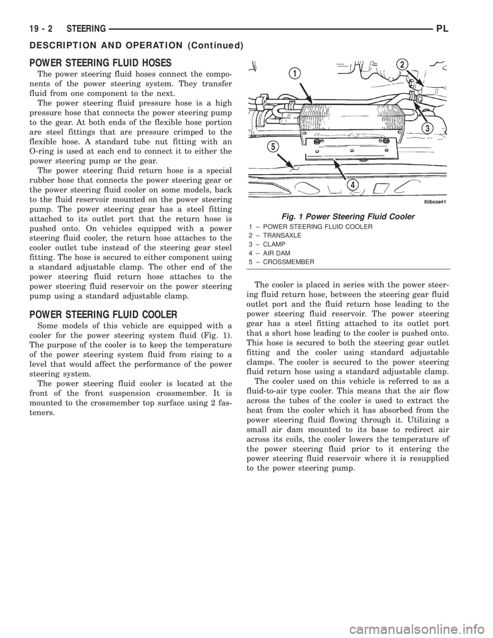
Some models of this vehicle are equipped with a
cooler for the power steering system fluid (Fig. 1).
The purpose of the cooler is to keep the temperature
of the power steering system fluid from rising to a
level that would affect the performance of the power
steering system.
The power steering fluid cooler is located at the
front of the front suspension crossmember. It is
mounted to the crossmember top surface using 2 fas-
teners.The cooler is placed in series with the power steer-
ing fluid return hose, between the steering gear fluid
outlet port and the fluid return hose leading to the
power steering fluid reservoir. The power steering
gear has a steel fitting attached to its outlet port
that a short hose leading to the cooler is pushed onto.
This hose is secured to both the steering gear outlet
fitting and the cooler using standard adjustable
clamps. The cooler is secured to the power steering
fluid return hose using a standard adjustable clamp.
The cooler used on this vehicle is referred to as a
fluid-to-air type cooler. This means that the air flow
across the tubes of the cooler is used to extract the
heat from the cooler which it has absorbed from the
power steering fluid flowing through it. Utilizing a
small air dam mounted to its base to redirect air
across its coils, the cooler lowers the temperature of
the power steering fluid prior to it entering the
power steering fluid reservoir where it is resupplied
to the power steering pump.
Fig. 1 Power Steering Fluid Cooler
1 ± POWER STEERING FLUID COOLER
2 ± TRANSAXLE
3 ± CLAMP
4 ± AIR DAM
5 ± CROSSMEMBER
19 - 2 STEERINGPL
DESCRIPTION AND OPERATION (Continued)
Page 887 of 1285
POWER STEERING PUMP
TABLE OF CONTENTS
page page
DESCRIPTION AND OPERATION
POWER STEERING PUMP.................16
POWER STEERING FLUID RESERVOIR.......17
SERVICE PROCEDURES
POWER STEERING PUMP INITIAL
OPERATION...........................17
REMOVAL AND INSTALLATION
SERVICE WARNINGS AND CAUTIONS........17
POWER STEERING PUMP.................17DISASSEMBLY AND ASSEMBLY
POWER STEERING PUMP (PULLEY).........19
SPECIFICATIONS
POWER STEERING PUMP FLOW
SPECIFICATIONS.......................20
POWER STEERING FASTENER TORQUE
SPECIFICATIONS.......................20
SPECIAL TOOLS
POWER STEERING PUMP.................20
DESCRIPTION AND OPERATION
POWER STEERING PUMP
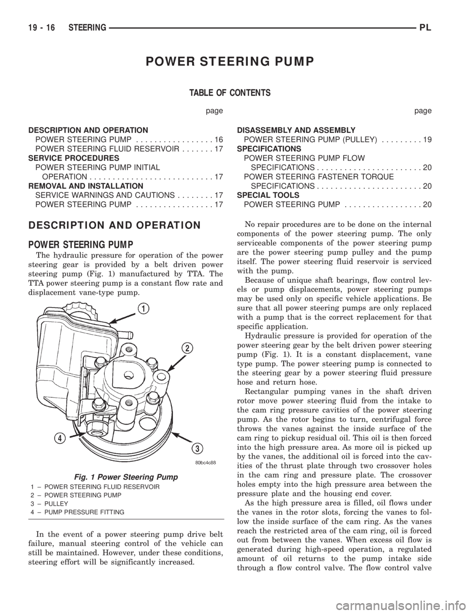
The hydraulic pressure for operation of the power
steering gear is provided by a belt driven power
steering pump (Fig. 1) manufactured by TTA. The
TTA power steering pump is a constant flow rate and
displacement vane-type pump.
In the event of a power steering pump drive belt
failure, manual steering control of the vehicle can
still be maintained. However, under these conditions,
steering effort will be significantly increased.No repair procedures are to be done on the internal
components of the power steering pump. The only
serviceable components of the power steering pump
are the power steering pump pulley and the pump
itself. The power steering fluid reservoir is serviced
with the pump.
Because of unique shaft bearings, flow control lev-
els or pump displacements, power steering pumps
may be used only on specific vehicle applications. Be
sure that all power steering pumps are only replaced
with a pump that is the correct replacement for that
specific application.
Hydraulic pressure is provided for operation of the
power steering gear by the belt driven power steering
pump (Fig. 1). It is a constant displacement, vane
type pump. The power steering pump is connected to
the steering gear by a power steering fluid pressure
hose and return hose.
Rectangular pumping vanes in the shaft driven
rotor move power steering fluid from the intake to
the cam ring pressure cavities of the power steering
pump. As the rotor begins to turn, centrifugal force
throws the vanes against the inside surface of the
cam ring to pickup residual oil. This oil is then forced
into the high pressure area. As more oil is picked up
by the vanes, the additional oil is forced into the cav-
ities of the thrust plate through two crossover holes
in the cam ring and pressure plate. The crossover
holes empty into the high pressure area between the
pressure plate and the housing end cover.
As the high pressure area is filled, oil flows under
the vanes in the rotor slots, forcing the vanes to fol-
low the inside surface of the cam ring. As the vanes
reach the restricted area of the cam ring, oil is forced
out from between the vanes. When excess oil flow is
generated during high-speed operation, a regulated
amount of oil returns to the pump intake side
through a flow control valve. The flow control valve
Fig. 1 Power Steering Pump
1 ± POWER STEERING FLUID RESERVOIR
2 ± POWER STEERING PUMP
3 ± PULLEY
4 ± PUMP PRESSURE FITTING
19 - 16 STEERINGPL
Page 888 of 1285
reduces the power required to drive the pump and
holds down temperature build-up.
When steering conditions exceed maximum pres-
sure requirements, such as when the wheels are
turned against the stops, the pressure built up in the
steering gear exerts pressure on the spring end of the
flow control valve. The high pressure lifts the relief
valve ball from its seat and allows oil to flow through
a trigger orifice located in the outlet fitting. This
reduces pressure on the spring end of the flow con-
trol valve which then opens and allows the oil to
return to the intake side of the pump. This action
limits maximum pressure output of the pump to a
safe level.
Under normal power steering pump operating con-
ditions, pressure requirements of the pump are below
maximum, causing the pressure relief valve to
remain closed.
POWER STEERING FLUID RESERVOIR
The power steering fluid reservoir is mounted on
the power steering pump using 3 bolts (Fig. 1). It
stores fluid for the power steering system.
The power steering fluid reservoir is considered an
integral part of the power steering pump and is not
serviced separately.
SERVICE PROCEDURES
POWER STEERING PUMP INITIAL OPERATION
CAUTION: The fluid level should be checked with
engine off to prevent injury from moving compo-
nents. Use only MoparTPower Steering Fluid. Do
not use automatic transmission fluid. Do not over-
fill.
Wipe the filler cap clean, then check the fluid level.
The dipstick should indicateCOLDwhen the fluid is
at normal temperature, approximately 21ÉC to 27ÉC
(70ÉF to 80ÉF).
(1) Fill the power steering fluid reservoir to the
proper level and let the fluid settle for at least two
minutes.
(2) Start the engine and let run for a few seconds,
then turn the engine off.
(3) Add fluid if necessary. Repeat the above proce-
dure until the fluid level remains constant after run-
ning the engine.
(4) Raise the front wheels off the ground.
(5) Start the engine. Slowly turn the steering
wheel right and left, lightly contacting the wheel
stops.
(6) Add power steering fluid if necessary.
(7) Lower the vehicle and turn the steering wheel
slowly from lock to lock.(8) Stop the engine. Check the fluid level and refill
as required.
(9) If the fluid is extremely foamy, allow the vehi-
cle to stand a few minutes and repeat the above pro-
cedure.
REMOVAL AND INSTALLATION
SERVICE WARNINGS AND CAUTIONS
WARNING: POWER STEERING FLUID, ENGINE
PARTS AND EXHAUST SYSTEM MAY BE
EXTREMELY HOT IF ENGINE HAS BEEN RUNNING.
DO NOT START ENGINE WITH ANY LOOSE OR DIS-
CONNECTED HOSES. DO NOT ALLOW HOSES TO
TOUCH HOT EXHAUST MANIFOLD OR CATALYST.
WARNING: FLUID LEVEL SHOULD BE CHECKED
WITH THE ENGINE OFF TO PREVENT PERSONAL
INJURY FROM MOVING PARTS.
CAUTION: When the system is open, cap all open
ends of the hoses, power steering pump fittings or
power steering gear ports to prevent entry of for-
eign material into the components.
NOTE: Do not use any type of automatic transmis-
sion fluid in the power steering system.
POWER STEERING PUMP
NOTE: Before proceeding with this removal and
installation procedure, review SERVICE WARNINGS
AND CAUTIONS at the beginning of REMOVAL AND
INSTALLATION in this section.
REMOVAL
(1) Remove battery cable from the negative post on
the battery.
(2) Siphon as much fluid as possible from the
power steering fluid reservoir.
(3) Remove the power steering pump drive belt
from the power steering pump pulley. Refer to
ACCESSORY DRIVE BELTS in the COOLING SYS-
TEM service manual group for the required removal
and installation procedure.
(4) Remove the hose clamp securing the return
hose to the power steering fluid reservoir. Slide the
hose off the end of the reservoir fitting. (Fig. 2).
(5) Back out the tube nut securing the power
steering fluid pressure hose to the power steering
pump and remove the hose from the pump (Fig. 2).
PLSTEERING 19 - 17
DESCRIPTION AND OPERATION (Continued)
Page 892 of 1285
STEERING GEAR
TABLE OF CONTENTS
page page
DESCRIPTION AND OPERATION
POWER STEERING GEAR..................21
REMOVAL AND INSTALLATION
SERVICE WARNINGS AND CAUTIONS........22
POWER STEERING GEAR..................22
OUTER TIE ROD.........................26SPECIFICATIONS
POWER STEERING GEAR FASTENER
TORQUE SPECIFICATIONS...............28
SPECIAL TOOLS
POWER STEERING GEAR..................28
DESCRIPTION AND OPERATION
POWER STEERING GEAR
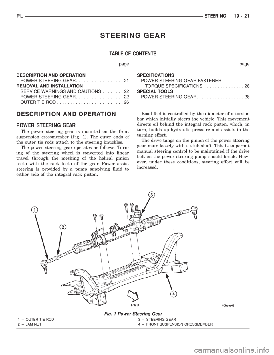
The power steering gear is mounted on the front
suspension crossmember (Fig. 1). The outer ends of
the outer tie rods attach to the steering knuckles.
The power steering gear operates as follows: Turn-
ing of the steering wheel is converted into linear
travel through the meshing of the helical pinion
teeth with the rack teeth of the gear. Power assist
steering is provided by a pump supplying fluid to
either side of the integral rack piston.Road feel is controlled by the diameter of a torsion
bar which initially steers the vehicle. This movement
directs oil behind the integral rack piston, which, in
turn, builds up hydraulic pressure and assists in the
turning effort.
The drive tangs on the pinion of the power steering
gear mate loosely with a stub shaft. This is to permit
manual steering control to be maintained if the drive
belt on the power steering pump should break. How-
ever, under these conditions, steering effort will be
increased.
Fig. 1 Power Steering Gear
1 ± OUTER TIE ROD
2 ± JAM NUT3 ± STEERING GEAR
4 ± FRONT SUSPENSION CROSSMEMBER
PLSTEERING 19 - 21
Page 917 of 1285
LOW LUBRICANT LEVEL
Insufficient transaxle lubricant is usually the
result of leaks, or inaccurate fluid level check or refill
method. Leakage is evident by the presence of oil
around the leak point. If leakage is not evident, the
condition is probably the result of an underfill.
If air±powered lubrication equipment is used to fill
a transaxle, be sure the equipment is properly cali-
brated. Equipment out of calibration can lead to an
underfill condition.
FLUID LEAKS
Fluid leaks can occur around the input shaft seal,
axleshaft seals, case split lines, and the end cover. Be
careful not to misdiagnose an input shaft seal leak
for an engine rear main seal leak. Also, the transaxle
case sealer (split line) will accumulate dirt and look
like an oil leak.
CLUTCH PROBLEMS
Worn, damaged, or misaligned clutch components
can cause difficult shifting, gear clash, and noise.
A worn or damaged clutch disc, pressure plate, or
release bearing can cause hard shifting and gear
clash.
SERVICE PROCEDURES
FLUID DRAIN AND FILL
All NV T350 (A-578) transaxles are equipped with
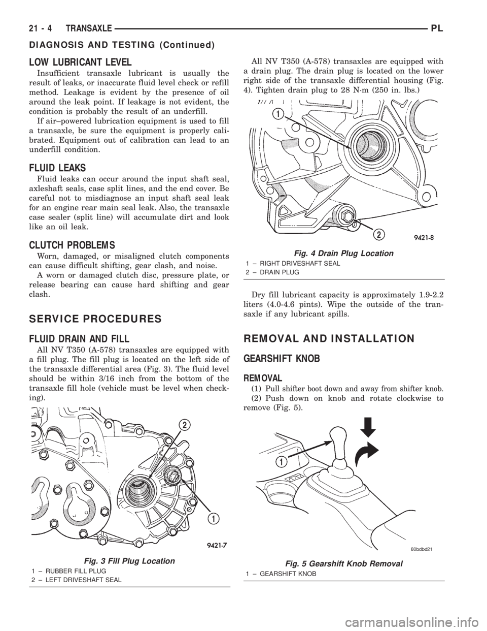
a fill plug. The fill plug is located on the left side of
the transaxle differential area (Fig. 3). The fluid level
should be within 3/16 inch from the bottom of the
transaxle fill hole (vehicle must be level when check-
ing).All NV T350 (A-578) transaxles are equipped with
a drain plug. The drain plug is located on the lower
right side of the transaxle differential housing (Fig.
4). Tighten drain plug to 28 N´m (250 in. lbs.)
Dry fill lubricant capacity is approximately 1.9-2.2
liters (4.0-4.6 pints). Wipe the outside of the tran-
saxle if any lubricant spills.
REMOVAL AND INSTALLATION
GEARSHIFT KNOB
REMOVAL
(1)Pull shifter boot down and away from shifter knob.
(2) Push down on knob and rotate clockwise to
remove (Fig. 5).
Fig. 3 Fill Plug Location
1 ± RUBBER FILL PLUG
2 ± LEFT DRIVESHAFT SEAL
Fig. 4 Drain Plug Location
1 ± RIGHT DRIVESHAFT SEAL
2 ± DRAIN PLUG
Fig. 5 Gearshift Knob Removal
1 ± GEARSHIFT KNOB
21 - 4 TRANSAXLEPL
DIAGNOSIS AND TESTING (Continued)
Page 961 of 1285
SHIFT CROSSOVER SHAFT BUSHING
REMOVAL
(1) Install slide hammer #3752 through the cross-
over bushing.
(2) Thread nut and washer onto slide hammer.
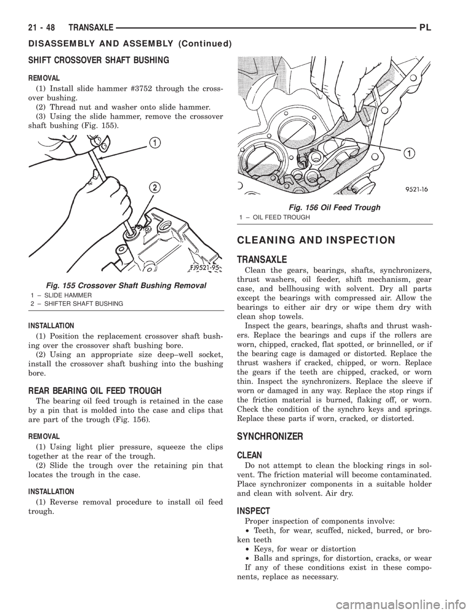
(3) Using the slide hammer, remove the crossover
shaft bushing (Fig. 155).
INSTALLATION
(1) Position the replacement crossover shaft bush-
ing over the crossover shaft bushing bore.
(2) Using an appropriate size deep±well socket,
install the crossover shaft bushing into the bushing
bore.
REAR BEARING OIL FEED TROUGH
The bearing oil feed trough is retained in the case
by a pin that is molded into the case and clips that
are part of the trough (Fig. 156).
REMOVAL
(1) Using light plier pressure, squeeze the clips
together at the rear of the trough.
(2) Slide the trough over the retaining pin that
locates the trough in the case.
INSTALLATION
(1) Reverse removal procedure to install oil feed
trough.
CLEANING AND INSPECTION
TRANSAXLE
Clean the gears, bearings, shafts, synchronizers,
thrust washers, oil feeder, shift mechanism, gear
case, and bellhousing with solvent. Dry all parts
except the bearings with compressed air. Allow the
bearings to either air dry or wipe them dry with
clean shop towels.
Inspect the gears, bearings, shafts and thrust wash-
ers. Replace the bearings and cups if the rollers are
worn, chipped, cracked, flat spotted, or brinnelled, or if
the bearing cage is damaged or distorted. Replace the
thrust washers if cracked, chipped, or worn. Replace
the gears if the teeth are chipped, cracked, or worn
thin. Inspect the synchronizers. Replace the sleeve if
worn or damaged in any way. Replace the stop rings if
the friction material is burned, flaking off, or worn.
Check the condition of the synchro keys and springs.
Replace these parts if worn, cracked, or distorted.
SYNCHRONIZER
CLEAN
Do not attempt to clean the blocking rings in sol-
vent. The friction material will become contaminated.
Place synchronizer components in a suitable holder
and clean with solvent. Air dry.
INSPECT
Proper inspection of components involve:
²Teeth, for wear, scuffed, nicked, burred, or bro-
ken teeth
²Keys, for wear or distortion
²Balls and springs, for distortion, cracks, or wear
If any of these conditions exist in these compo-
nents, replace as necessary.
Fig. 155 Crossover Shaft Bushing Removal
1 ± SLIDE HAMMER
2 ± SHIFTER SHAFT BUSHING
Fig. 156 Oil Feed Trough
1 ± OIL FEED TROUGH
21 - 48 TRANSAXLEPL
DISASSEMBLY AND ASSEMBLY (Continued)