2000 DODGE NEON low oil pressure
[x] Cancel search: low oil pressurePage 679 of 1285
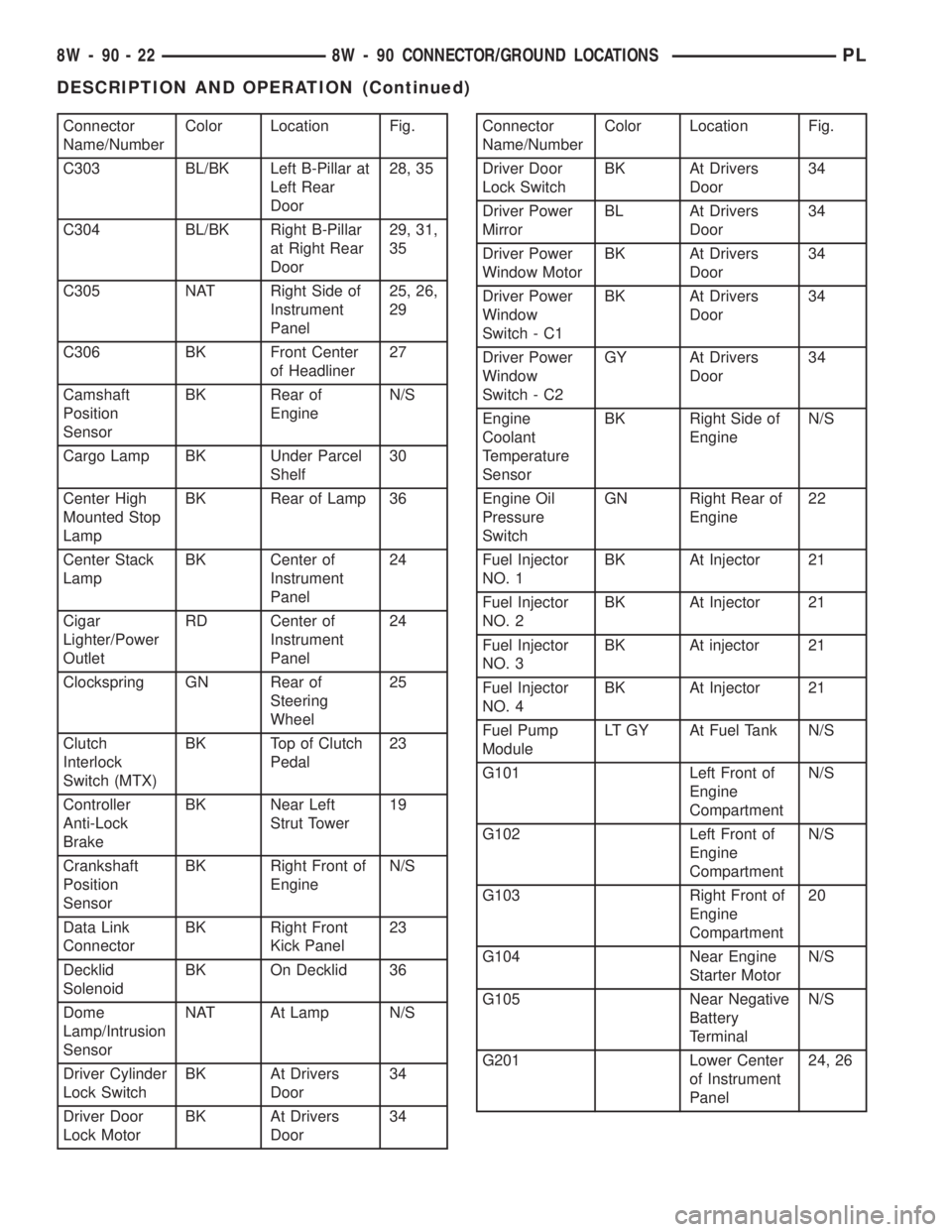
Connector
Name/NumberColor Location Fig.
C303 BL/BK Left B-Pillar at
Left Rear
Door28, 35
C304 BL/BK Right B-Pillar
at Right Rear
Door29, 31,
35
C305 NAT Right Side of
Instrument
Panel25, 26,
29
C306 BK Front Center
of Headliner27
Camshaft
Position
SensorBK Rear of
EngineN/S
Cargo Lamp BK Under Parcel
Shelf30
Center High
Mounted Stop
LampBK Rear of Lamp 36
Center Stack
LampBK Center of
Instrument
Panel24
Cigar
Lighter/Power
OutletRD Center of
Instrument
Panel24
Clockspring GN Rear of
Steering
Wheel25
Clutch
Interlock
Switch (MTX)BK Top of Clutch
Pedal23
Controller
Anti-Lock
BrakeBK Near Left
Strut Tower19
Crankshaft
Position
SensorBK Right Front of
EngineN/S
Data Link
ConnectorBK Right Front
Kick Panel23
Decklid
SolenoidBK On Decklid 36
Dome
Lamp/Intrusion
SensorNAT At Lamp N/S
Driver Cylinder
Lock SwitchBK At Drivers
Door34
Driver Door
Lock MotorBK At Drivers
Door34Connector
Name/NumberColor Location Fig.
Driver Door
Lock SwitchBK At Drivers
Door34
Driver Power
MirrorBL At Drivers
Door34
Driver Power
Window MotorBK At Drivers
Door34
Driver Power
Window
Switch - C1BK At Drivers
Door34
Driver Power
Window
Switch - C2GY At Drivers
Door34
Engine
Coolant
Temperature
SensorBK Right Side of
EngineN/S
Engine Oil
Pressure
SwitchGN Right Rear of
Engine22
Fuel Injector
NO. 1BK At Injector 21
Fuel Injector
NO. 2BK At Injector 21
Fuel Injector
NO. 3BK At injector 21
Fuel Injector
NO. 4BK At Injector 21
Fuel Pump
ModuleLT GY At Fuel Tank N/S
G101 Left Front of
Engine
CompartmentN/S
G102 Left Front of
Engine
CompartmentN/S
G103 Right Front of
Engine
Compartment20
G104 Near Engine
Starter MotorN/S
G105 Near Negative
Battery
TerminalN/S
G201 Lower Center
of Instrument
Panel24, 26
8W - 90 - 22 8W - 90 CONNECTOR/GROUND LOCATIONSPL
DESCRIPTION AND OPERATION (Continued)
Page 680 of 1285
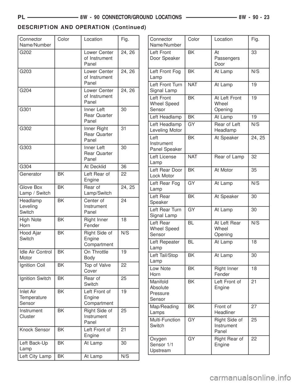
Connector
Name/NumberColor Location Fig.
G202 Lower Center
of Instrument
Panel24, 26
G203 Lower Center
of Instrument
Panel24, 26
G204 Lower Center
of Instrument
Panel24, 26
G301 Inner Left
Rear Quarter
Panel30
G302 Inner Right
Rear Quarter
Panel31
G303 Inner Left
Rear Quarter
Panel30
G304 At Decklid 36
Generator BK Left Rear of
Engine22
Glove Box
Lamp / SwitchBK Rear of
Lamp/Switch24, 25
Headlamp
Leveling
SwitchBK Center of
Instrument
Panel24
High Note
HornBK Right Inner
Fender18
Hood Ajar
SwitchBK Right Side of
Engine
CompartmentN/S
Idle Air Control
MotorBK On Throttle
Body19
Ignition Coil BK Top of Valve
Cover22
Ignition Switch BK Rear of
Switch25
Inlet Air
Temperature
SensorBK Left Front of
Engine
Compartment19
Instrument
ClusterBK Right Side of
Instrument
Panel25
Knock Sensor BK Left Front of
Engine21
Left Back-Up
LampBK At Lamp 30
Left City Lamp BK At Lamp N/SConnector
Name/NumberColor Location Fig.
Left Front
Door SpeakerBK At
Passengers
Door33
Left Front Fog
LampBK At Lamp N/S
Left Front Turn
Signal LampNAT At Lamp 19
Left Front
Wheel Speed
SensorBK At Left Front
Wheel
Opening19
Left Headlamp BK At Lamp 19
Left Headlamp
Leveling MotorGY Rear of Left
HeadlampN/S
Left
Instrument
Panel SpeakerBK At Speaker 24, 25
Left License
LampNAT Rear of Lamp 32
Left Rear Door
Lock MotorBK At Motor 35
Left Rear Fog
LampGY At Lamp N/S
Left Rear
SpeakerBK At Speaker 30
Left Rear Turn
Signal LampGY At Lamp 30
Left Rear
Wheel Speed
SensorBL At Left Rear
Wheel
OpeningN/S
Left Repeater
LampBL At Lamp 18
Left Tail/Stop
LampBK At Lamp 30
Low Note
HornBK Right Inner
Fender18
Manifold
Absolute
Pressure
SensorBK Left Front of
Engine21
Map/Reading
LampsBK Front of
Headliner27
Multi-Function
SwitchGY Right Side of
Instrument
Panel25
Oxygen
Sensor 1/1
UpstreamGY Right Rear of
Engine22
PL8W - 90 CONNECTOR/GROUND LOCATIONS 8W - 90 - 23
DESCRIPTION AND OPERATION (Continued)
Page 698 of 1285
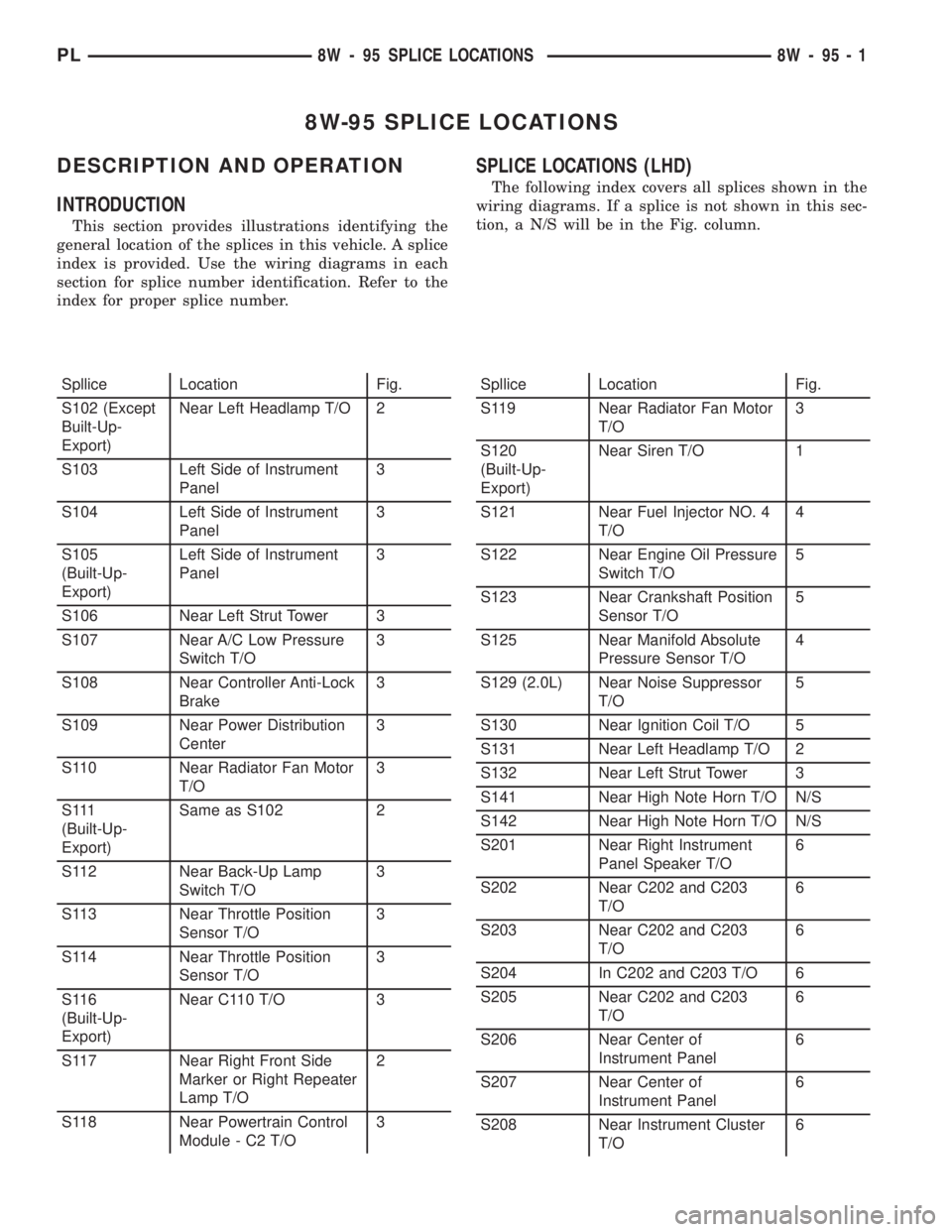
8W-95 SPLICE LOCATIONS
DESCRIPTION AND OPERATION
INTRODUCTION
This section provides illustrations identifying the
general location of the splices in this vehicle. A splice
index is provided. Use the wiring diagrams in each
section for splice number identification. Refer to the
index for proper splice number.
SPLICE LOCATIONS (LHD)
The following index covers all splices shown in the
wiring diagrams. If a splice is not shown in this sec-
tion, a N/S will be in the Fig. column.
Spllice Location Fig.
S102 (Except
Built-Up-
Export)Near Left Headlamp T/O 2
S103 Left Side of Instrument
Panel3
S104 Left Side of Instrument
Panel3
S105
(Built-Up-
Export)Left Side of Instrument
Panel3
S106 Near Left Strut Tower 3
S107 Near A/C Low Pressure
Switch T/O3
S108 Near Controller Anti-Lock
Brake3
S109 Near Power Distribution
Center3
S110 Near Radiator Fan Motor
T/O3
S 111
(Built-Up-
Export)Same as S102 2
S112 Near Back-Up Lamp
Switch T/O3
S113 Near Throttle Position
Sensor T/O3
S114 Near Throttle Position
Sensor T/O3
S116
(Built-Up-
Export)Near C110 T/O 3
S117 Near Right Front Side
Marker or Right Repeater
Lamp T/O2
S118 Near Powertrain Control
Module - C2 T/O3Spllice Location Fig.
S119 Near Radiator Fan Motor
T/O3
S120
(Built-Up-
Export)Near Siren T/O 1
S121 Near Fuel Injector NO. 4
T/O4
S122 Near Engine Oil Pressure
Switch T/O5
S123 Near Crankshaft Position
Sensor T/O5
S125 Near Manifold Absolute
Pressure Sensor T/O4
S129 (2.0L) Near Noise Suppressor
T/O5
S130 Near Ignition Coil T/O 5
S131 Near Left Headlamp T/O 2
S132 Near Left Strut Tower 3
S141 Near High Note Horn T/O N/S
S142 Near High Note Horn T/O N/S
S201 Near Right Instrument
Panel Speaker T/O6
S202 Near C202 and C203
T/O6
S203 Near C202 and C203
T/O6
S204 In C202 and C203 T/O 6
S205 Near C202 and C203
T/O6
S206 Near Center of
Instrument Panel6
S207 Near Center of
Instrument Panel6
S208 Near Instrument Cluster
T/O6
PL8W - 95 SPLICE LOCATIONS 8W - 95 - 1
Page 710 of 1285
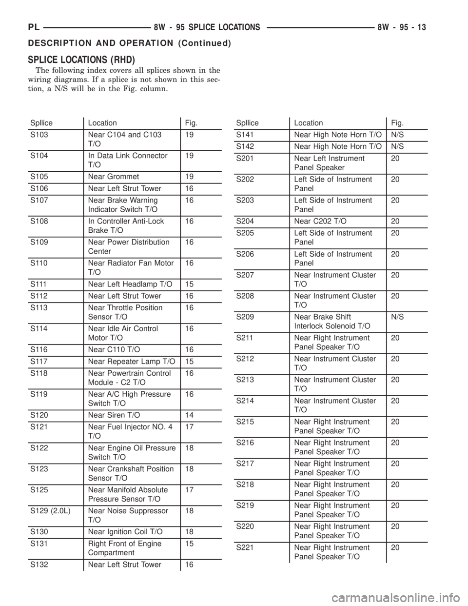
SPLICE LOCATIONS (RHD)
The following index covers all splices shown in the
wiring diagrams. If a splice is not shown in this sec-
tion, a N/S will be in the Fig. column.
Spllice Location Fig.
S103 Near C104 and C103
T/O19
S104 In Data Link Connector
T/O19
S105 Near Grommet 19
S106 Near Left Strut Tower 16
S107 Near Brake Warning
Indicator Switch T/O16
S108 In Controller Anti-Lock
Brake T/O16
S109 Near Power Distribution
Center16
S110 Near Radiator Fan Motor
T/O16
S111 Near Left Headlamp T/O 15
S112 Near Left Strut Tower 16
S113 Near Throttle Position
Sensor T/O16
S114 Near Idle Air Control
Motor T/O16
S116 Near C110 T/O 16
S117 Near Repeater Lamp T/O 15
S118 Near Powertrain Control
Module - C2 T/O16
S119 Near A/C High Pressure
Switch T/O16
S120 Near Siren T/O 14
S121 Near Fuel Injector NO. 4
T/O17
S122 Near Engine Oil Pressure
Switch T/O18
S123 Near Crankshaft Position
Sensor T/O18
S125 Near Manifold Absolute
Pressure Sensor T/O17
S129 (2.0L) Near Noise Suppressor
T/O18
S130 Near Ignition Coil T/O 18
S131 Right Front of Engine
Compartment15
S132 Near Left Strut Tower 16Spllice Location Fig.
S141 Near High Note Horn T/O N/S
S142 Near High Note Horn T/O N/S
S201 Near Left Instrument
Panel Speaker20
S202 Left Side of Instrument
Panel20
S203 Left Side of Instrument
Panel20
S204 Near C202 T/O 20
S205 Left Side of Instrument
Panel20
S206 Left Side of Instrument
Panel20
S207 Near Instrument Cluster
T/O20
S208 Near Instrument Cluster
T/O20
S209 Near Brake Shift
Interlock Solenoid T/ON/S
S211 Near Right Instrument
Panel Speaker T/O20
S212 Near Instrument Cluster
T/O20
S213 Near Instrument Cluster
T/O20
S214 Near Instrument Cluster
T/O20
S215 Near Right Instrument
Panel Speaker T/O20
S216 Near Right Instrument
Panel Speaker T/O20
S217 Near Right Instrument
Panel Speaker T/O20
S218 Near Right Instrument
Panel Speaker T/O20
S219 Near Right Instrument
Panel Speaker T/O20
S220 Near Right Instrument
Panel Speaker T/O20
S221 Near Right Instrument
Panel Speaker T/O20
PL8W - 95 SPLICE LOCATIONS 8W - 95 - 13
DESCRIPTION AND OPERATION (Continued)
Page 725 of 1285
MOPARtGASKET SEALANT
MopartGasket Sealant is a slow drying, perma-
nently soft sealer. This material is recommended for
sealing threaded fittings and gaskets against leakage
of oil and coolant. Can be used on threaded and
machined parts under all temperatures. This mate-
rial is used on engines with multi-layer steel (MLS)
cylinder head gaskets. This material also will pre-
vent corrosion. MopartGasket Sealant is available in
a 13 oz. aerosol can or 4 oz./16 oz. can w/applicator.
FORM-IN-PLACE GASKET AND SEALER
APPLICATION
Assembling parts using a form-in-place gasket
requires care but it's easier then using precut gas-
kets.
MopartGasket Maker material should be applied
sparingly 1 mm (0.040 in.) diameter or less of sealant
to one gasket surface. Be certain the material sur-
rounds each mounting hole. Excess material can eas-
ily be wiped off. Components should be torqued in
place within 15 minutes. The use of a locating dowel
is recommended during assembly to prevent smear-
ing material off the location.
MopartEngine RTV GEN II or ATF RTV gasket
material should be applied in a continuous bead
approximately 3 mm (0.120 in.) in diameter. All
mounting holes must be circled. For corner sealing, a
3.17 or 6.35 mm (1/8 or 1/4 in.) drop is placed in the
center of the gasket contact area. Uncured sealant
may be removed with a shop towel. Components
should be torqued in place while the sealant is still
wet to the touch (within 10 minutes). The usage of a
locating dowel is recommended during assembly to
prevent smearing material off the location.
MopartGasket Sealant in an aerosol can should be
applied using a thin, even coat sprayed completely
over both surfaces to be joined, and both sides of a
gasket. Then proceed with assembly. Material in a
can w/applicator can be brushed on evenly over the
sealing surfaces. Material in an aerosol can should be
used on engines with multi-layer steel gaskets.
ENGINE GASKET SURFACE PREPARATION
To ensure engine gasket sealing, proper surface
preparation must be performed, especially with the
use of aluminum engine components and multi-layer
steel cylinder head gaskets.
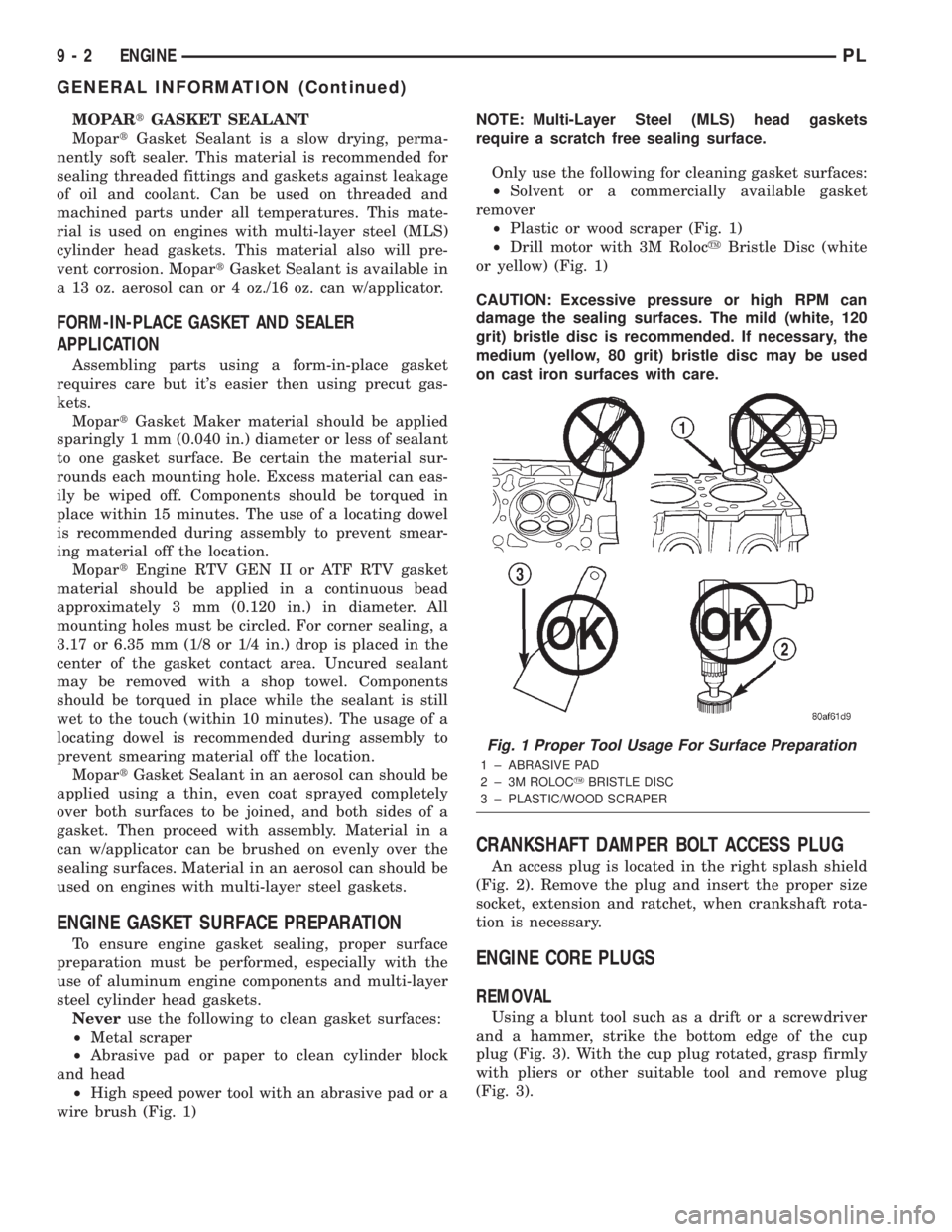
Neveruse the following to clean gasket surfaces:
²Metal scraper
²Abrasive pad or paper to clean cylinder block
and head
²High speed power tool with an abrasive pad or a
wire brush (Fig. 1)NOTE: Multi-Layer Steel (MLS) head gaskets
require a scratch free sealing surface.
Only use the following for cleaning gasket surfaces:
²Solvent or a commercially available gasket
remover
²Plastic or wood scraper (Fig. 1)
²Drill motor with 3M RolocyBristle Disc (white
or yellow) (Fig. 1)
CAUTION: Excessive pressure or high RPM can
damage the sealing surfaces. The mild (white, 120
grit) bristle disc is recommended. If necessary, the
medium (yellow, 80 grit) bristle disc may be used
on cast iron surfaces with care.
CRANKSHAFT DAMPER BOLT ACCESS PLUG
An access plug is located in the right splash shield
(Fig. 2). Remove the plug and insert the proper size
socket, extension and ratchet, when crankshaft rota-
tion is necessary.
ENGINE CORE PLUGS
REMOVAL
Using a blunt tool such as a drift or a screwdriver
and a hammer, strike the bottom edge of the cup
plug (Fig. 3). With the cup plug rotated, grasp firmly
with pliers or other suitable tool and remove plug
(Fig. 3).
Fig. 1 Proper Tool Usage For Surface Preparation
1 ± ABRASIVE PAD
2 ± 3M ROLOCYBRISTLE DISC
3 ± PLASTIC/WOOD SCRAPER
9 - 2 ENGINEPL
GENERAL INFORMATION (Continued)
Page 726 of 1285

CAUTION: Do not drive cup plug into the casting
as restricted cooling can result and cause serious
engine problems.
INSTALLATION
Thoroughly clean all debris/rust from inside of cup
plug hole in cylinder block or head. Be sure to
remove old sealer. Lightly coat inside of cup plug hole
with MopartStud and Bearing Mount Adhesive.
Make certain the new plug is cleaned of all oil or
grease. Using a proper driver, drive plug into hole so
that the sharp edge of the plug is at least 0.5 mm
(0.020 inch.) inside the lead in chamfer (Fig. 3).
It is not necessary to wait for curing of the sealant.
The cooling system can be refilled and the vehicle
placed in service immediately.
ENGINE PERFORMANCE
If a loss of performance is noticed, timing belt or
chain may have skipped one or two teeth. Camshaft
and crankshaft timing should be checked. Refer to
Group 9, Engine Timing belt or chain installation.
It is important that the vehicle is operating to it's
optimum performance level to maintain fuel economy
and lowest vehicle emissions. If vehicle is not operat-ing to these standards, refer to Engine Diagnosis in
this section. The following procedures can assist in
achieving the proper engine diagnosis.
(1) Test cranking amperage draw. Refer to Group
8B, Starting.
(2) Check intake manifold for vacuum leaks.
(3) Perform cylinder compression pressure test.
Refer to Engine Diagnosis in this section.
(4) Clean or replace spark plugs as necessary and
adjust gap as specified in Group 8D, Ignition System.
Tighten to specifications.
(5) Test resistance of spark plug cables. Refer to
Group 8D, Ignition System.
(6) Test ignition coils primary and secondary resis-
tance. Replace parts as necessary. Refer to Group 8D,
Ignition System.
(7) Check fuel pump pressure at idle and different
RPM ranges. Refer to Group 14, Fuel System for
specifications.
(8) The air filter elements should be replaced as
specified in Group 0, Lubrication and Maintenance.
(9) Inspect crankcase ventilation system. Refer to
Group 25, Emission Control Systems.
(10) Road test vehicle as a final test.HONING CYLINDER BORES
(1) Used carefully, the cylinder bore resizing hone,
recommended tool C-823 or equivalent, equipped
with 220 grit stones, is the best tool for this honing
procedure. In addition to deglazing, it will reduce
taper and out-of-round as well as removing light
scuffing, scoring or scratches. Usually a few strokes
Fig. 2 Access Plug
1 ± CRANKSHAFT BOLT ACCESS PLUG
2 ± RIGHT MOUNT BOLT ACCESS PLUG
3 ± FASCIA
4 ± SPLASH SHIELD
Fig. 3 Core Hole Plug Removal
1 ± CYLINDER BLOCK
2 ± REMOVE PLUG WITH PLIERS
3 ± STRIKE HERE WITH HAMMER
4 ± DRIFT PUNCH
5 ± CUP PLUG
PLENGINE 9 - 3
GENERAL INFORMATION (Continued)
Page 729 of 1285
any fluid that may possibly be in the cylinder under
pressure.
(4) With all spark plugs removed, rotate engine
crankshaft using a breaker bar and socket.
(5) Identify the fluid in the cylinder(s) (i.e., cool-
ant, fuel, oil or other).
(6) Make sure all fluid has been removed from the
cylinders. Inspect engine for damage (i.e., connecting
rods, pistons, valves, etc.).
(7) Repair engine or components as necessary to
prevent this problem from re-occurring.
CAUTION: Squirt approximately one teaspoon of oil
into the cylinders, rotate engine to lubricate the cyl-
inder walls to prevent damage on restart.
(8) Install new spark plugs.
(9) Drain engine oil and remove oil filter.
(10) Fill engine with specified amount of approved
oil and install new oil filter.
(11) Connect negative battery cable.
(12) Start engine and check for any leaks.
CHECKING ENGINE OIL LEVEL
The best time to check engine oil level is after it
has sat overnight, or if the engine has been running,allow the engine to be shut off for at least 5 minutes
before checking oil level.
Checking the oil while the vehicle is on level
ground will improve the accuracy of the oil level
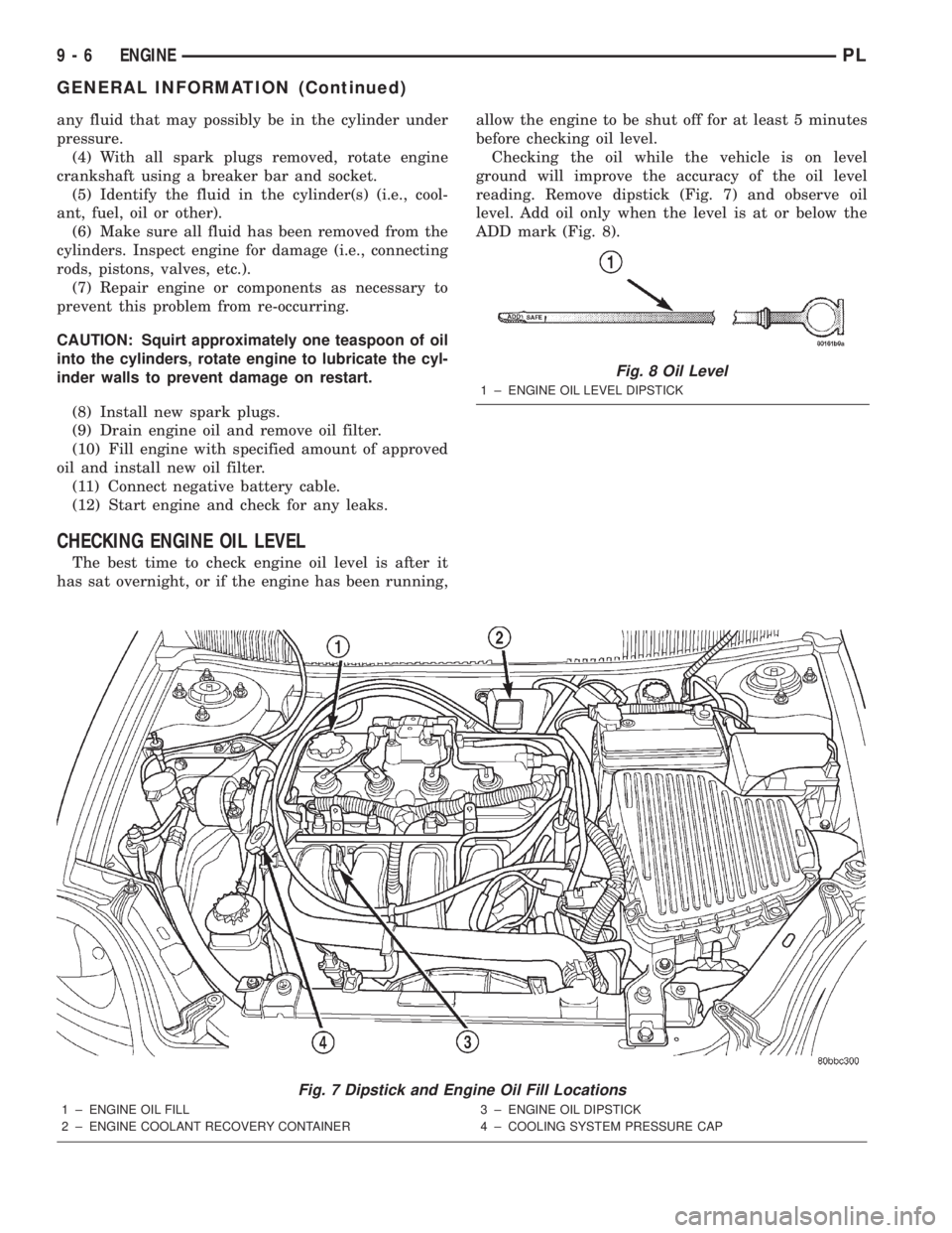
reading. Remove dipstick (Fig. 7) and observe oil
level. Add oil only when the level is at or below the
ADD mark (Fig. 8).
Fig. 7 Dipstick and Engine Oil Fill Locations
1 ± ENGINE OIL FILL
2 ± ENGINE COOLANT RECOVERY CONTAINER3 ± ENGINE OIL DIPSTICK
4 ± COOLING SYSTEM PRESSURE CAP
Fig. 8 Oil Level
1 ± ENGINE OIL LEVEL DIPSTICK
9 - 6 ENGINEPL
GENERAL INFORMATION (Continued)
Page 731 of 1285
ENGINE DIAGNOSIS
TABLE OF CONTENTS
page page
DIAGNOSIS AND TESTING
GENERAL INFORMATION...................8
INTAKE MANIFOLD LEAKAGE DIAGNOSIS......8
CYLINDER COMPRESSION PRESSURE TEST . . . 8
CYLINDER COMBUSTION PRESSURE
LEAKAGE TEST.........................9LASH ADJUSTER (TAPPET) NOISE
DIAGNOSIS............................9
ENGINE OIL LEAK INSPECTION..............9
ENGINE DIAGNOSISÐPERFORMANCE........11
ENGINE DIAGNOSISÐMECHANICAL.........12
DIAGNOSIS AND TESTING
GENERAL INFORMATION
Engine diagnosis is helpful in determining the
causes of malfunctions not detected and remedied by
routine maintenance.
These malfunctions may be classified as either
mechanical (e.g., a strange noise), or performance
(e.g., engine idles rough and stalls).
Refer to the Service DiagnosisÐMechanical Chart
and the Service DiagnosisÐPerformance Chart, for
possible causes and corrections of malfunctions. Refer
to Group 14, Fuel System, for the fuel system diag-
nosis.
Additional tests and diagnostic procedures may be
necessary for specific engine malfunctions that can-
not be isolated with the Service Diagnosis charts.
Information concerning additional tests and diagno-
sis is provided within the following:
²Cylinder Compression Pressure Test
²Cylinder Combustion Pressure Leakage Test
²Engine Cylinder Head Gasket Failure Diagnosis
²Intake Manifold Leakage Diagnosis
INTAKE MANIFOLD LEAKAGE DIAGNOSIS
An intake manifold air leak is characterized by
lower than normal manifold vacuum. Also, one or
more cylinders may not be functioning.
WARNING: USE EXTREME CAUTION WHEN THE
ENGINE IS OPERATING. DO NOT STAND IN A
DIRECT LINE WITH THE FAN. DO NOT PUT YOUR
HANDS NEAR THE PULLEYS, BELTS OR THE FAN.
DO NOT WEAR LOOSE CLOTHING.
(1) Start the engine.
(2) Spray a small stream of water (Spray Bottle) at
the suspected leak area.
(3) If engine RPM'S change, the area of the sus-
pected leak has been found.
(4) Repair as required.
CYLINDER COMPRESSION PRESSURE TEST
The results of a cylinder compression pressure test
can be utilized to diagnose several engine malfunc-
tions.
Ensure the battery is completely charged and the
engine starter motor is in good operating condition.
Otherwise the indicated compression pressures may
not be valid for diagnosis purposes.
(1) Check engine oil level and add oil if necessary.
(2) Drive the vehicle until engine reaches normal
operating temperature. Select a route free from traf-
fic and other forms of congestion, observe all traffic
laws, and accelerate through the gears several times
briskly.
(3) Remove all spark plugs from engine. As spark
plugs are being removed, check electrodes for abnor-
mal firing indicators fouled, hot, oily, etc. Record cyl-
inder number of spark plug for future reference.
(4) Disconnect coil wire from distributor and
secure to good ground to prevent a spark from start-
ing a fire (Conventional Ignition System). For Direct
Ignition System DIS disconnect the coil connector.
(5) Be sure throttle blade is fully open during the
compression check.
(6) Insert compression gage adaptor into the #1
spark plug hole in cylinder head. Crank engine until
maximum pressure is reached on gage. Record this
pressure as #1 cylinder pressure.
(7) Repeat the previous step for all remaining cyl-
inders.
(8) Compression should not be less than (689 kPa)
100 psi and not vary more than 25 percent from cyl-
inder to cylinder.
(9) If one or more cylinders have abnormally low
compression pressures, repeat the compression test.
(10) If the same cylinder or cylinders repeat an
abnormally low reading on the second compression
test, it could indicate the existence of a problem in
the cylinder in question.The recommended com-
pression pressures are to be used only as a
guide to diagnosing engine problems. An engine
9 - 8 ENGINEPL