2000 DODGE NEON low oil pressure
[x] Cancel search: low oil pressurePage 783 of 1285
(10) Install connecting rod lower bearing half and
cap. InstallNewbolts and tighten to 27 N´m (20 ft.
lbs.) plus 1/4 turn.
(11) Install cylinder head and oil pan. Refer to pro-
cedures in this section.
DISASSEMBLY AND ASSEMBLY
OIL PUMP
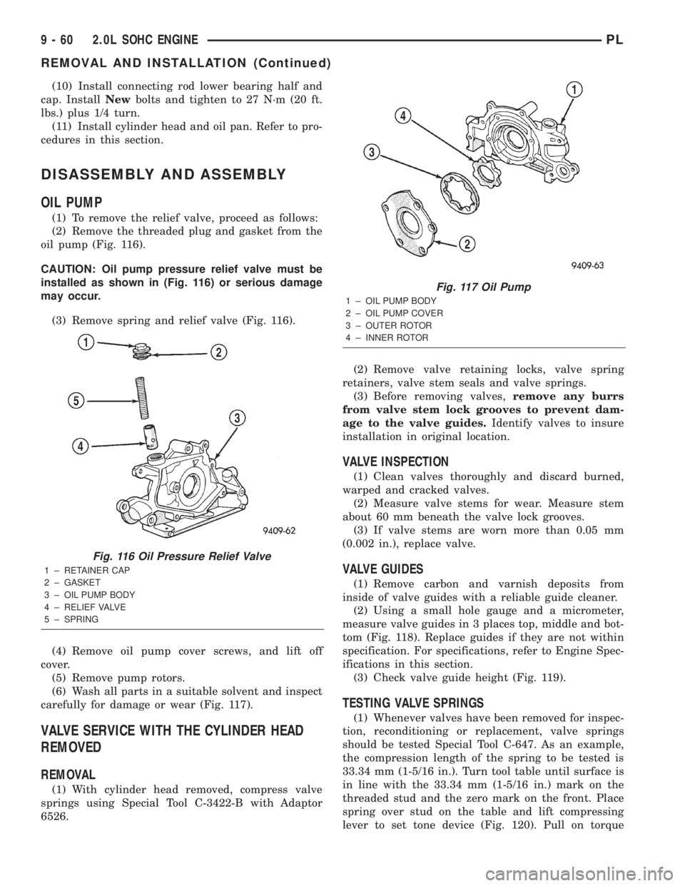
(1) To remove the relief valve, proceed as follows:
(2) Remove the threaded plug and gasket from the
oil pump (Fig. 116).
CAUTION: Oil pump pressure relief valve must be
installed as shown in (Fig. 116) or serious damage
may occur.
(3) Remove spring and relief valve (Fig. 116).
(4) Remove oil pump cover screws, and lift off
cover.
(5) Remove pump rotors.
(6) Wash all parts in a suitable solvent and inspect
carefully for damage or wear (Fig. 117).
VALVE SERVICE WITH THE CYLINDER HEAD
REMOVED
REMOVAL
(1) With cylinder head removed, compress valve
springs using Special Tool C-3422-B with Adaptor
6526.(2) Remove valve retaining locks, valve spring
retainers, valve stem seals and valve springs.
(3) Before removing valves,remove any burrs
from valve stem lock grooves to prevent dam-
age to the valve guides.Identify valves to insure
installation in original location.
VALVE INSPECTION
(1) Clean valves thoroughly and discard burned,
warped and cracked valves.
(2) Measure valve stems for wear. Measure stem
about 60 mm beneath the valve lock grooves.
(3) If valve stems are worn more than 0.05 mm
(0.002 in.), replace valve.
VALVE GUIDES
(1) Remove carbon and varnish deposits from
inside of valve guides with a reliable guide cleaner.
(2) Using a small hole gauge and a micrometer,
measure valve guides in 3 places top, middle and bot-
tom (Fig. 118). Replace guides if they are not within
specification. For specifications, refer to Engine Spec-
ifications in this section.
(3) Check valve guide height (Fig. 119).
TESTING VALVE SPRINGS
(1) Whenever valves have been removed for inspec-
tion, reconditioning or replacement, valve springs
should be tested Special Tool C-647. As an example,
the compression length of the spring to be tested is
33.34 mm (1-5/16 in.). Turn tool table until surface is
in line with the 33.34 mm (1-5/16 in.) mark on the
threaded stud and the zero mark on the front. Place
spring over stud on the table and lift compressing
lever to set tone device (Fig. 120). Pull on torque
Fig. 116 Oil Pressure Relief Valve
1 ± RETAINER CAP
2 ± GASKET
3 ± OIL PUMP BODY
4 ± RELIEF VALVE
5 ± SPRING
Fig. 117 Oil Pump
1 ± OIL PUMP BODY
2 ± OIL PUMP COVER
3 ± OUTER ROTOR
4 ± INNER ROTOR
9 - 60 2.0L SOHC ENGINEPL
REMOVAL AND INSTALLATION (Continued)
Page 785 of 1285
then set valve in place. Rotate the valve with light
pressure. If the blue is transferred to the center of
valve face, contact is satisfactory. If the blue is trans-
ferred to top edge of the valve face, lower valve seat
with a 15 degrees stone. If the blue is transferred to
the bottom edge of valve face raise valve seat with a
65 degrees stone.
(6) Valve seats which are worn or burned can be
reworked, provided that correct angle and seat width
are maintained. The intake valve seat must be ser-
viced when the valve seat width is 2.0 mm (0.079 in.)
or greater. The exhaust valve seat must be serviced
when the valve seat width is 2.5 mm (0.098 in.) or
greater. Otherwise the cylinder head must be
replaced.
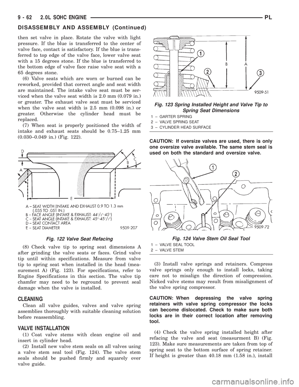
(7) When seat is properly positioned the width of
intake and exhaust seats should be 0.75±1.25 mm
(0.030±0.049 in.) (Fig. 122).
(8) Check valve tip to spring seat dimensions A
after grinding the valve seats or faces. Grind valve
tip until within specifications. Measure from valve
tip to spring seat when installed in the head (mea-
surement A) (Fig. 123). For specifications, refer to
Engine Specifications in this section. The valve tip
chamfer may need to be reground to prevent seal
damage when the valve is installed.
CLEANING
Clean all valve guides, valves and valve spring
assemblies thoroughly with suitable cleaning solution
before reassembling.
VALVE INSTALLATION
(1) Coat valve stems with clean engine oil and
insert in cylinder head.
(2) Install new valve stem seals on all valves using
a valve stem seal tool (Fig. 124). The valve stem
seals should be pushed firmly and squarely over
valve guide.CAUTION: If oversize valves are used, there is only
one oversize valve available. The same stem seal is
used on both the standard and oversize valve.
(3) Install valve springs and retainers. Compress
valve springs only enough to install locks, taking
care not to misalign the direction of compression.
Nicked valve stems may result from misalignment of
the valve spring compressor.
CAUTION: When depressing the valve spring
retainers with valve spring compressor the locks
can become dislocated. Check to make sure both
locks are in their correct location after removing
tool.
(4) Check the valve spring installed height after
refacing the valve and seat (measurment B) (Fig.
123). Make sure measurements are taken from top of
spring seat to the bottom surface of spring retainer.
If height is greater than 40.18 mm (1.58 in.), install
Fig. 122 Valve Seat Refacing
Fig. 123 Spring Installed Height and Valve Tip to
Spring Seat Dimensions
1 ± GARTER SPRING
2 ± VALVE SPRING SEAT
3 ± CYLINDER HEAD SURFACE
Fig. 124 Valve Stem Oil Seal Tool
1 ± VALVE SEAL TOOL
2 ± VALVE STEM
9 - 62 2.0L SOHC ENGINEPL
DISASSEMBLY AND ASSEMBLY (Continued)
Page 786 of 1285
a 0.762 mm (0.030 in.) spacer under the valve spring
seat to bring spring height back within specification.
(5) Install rocker arm shafts as previously
described in this section.
(6) Checking dry lash. Dry lash is the amount of
clearance that exists between the base circle of an
installed cam and the rocker arm roller when the
adjuster is drained of oil and completely collapsed.
Specified dry lash is 1.17 mm (0.046 in.) for intake
and 1.28 mm (0.050 in.) for exhaust. After performing
dry lash check, refill adjuster with oil and allow 10
minutes for adjuster(s) to bleed down before rotating
cam.
CLEANING AND INSPECTION
INTAKE MANIFOLD
CLEAN AND INSPECT
Check for:
²Inspect manifold for cracks or distortions.
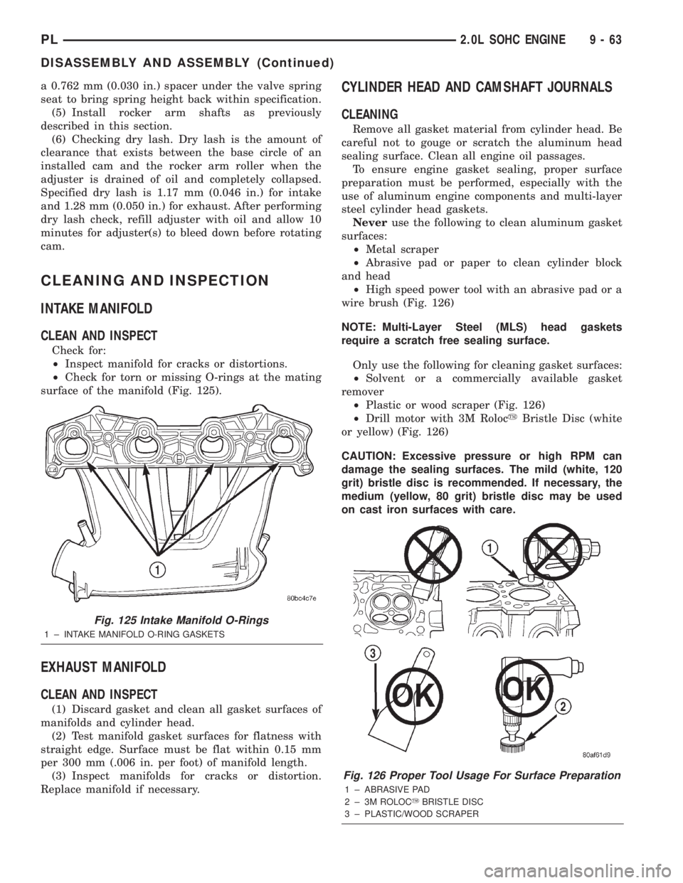
²Check for torn or missing O-rings at the mating
surface of the manifold (Fig. 125).
EXHAUST MANIFOLD
CLEAN AND INSPECT
(1) Discard gasket and clean all gasket surfaces of
manifolds and cylinder head.
(2) Test manifold gasket surfaces for flatness with
straight edge. Surface must be flat within 0.15 mm
per 300 mm (.006 in. per foot) of manifold length.
(3) Inspect manifolds for cracks or distortion.
Replace manifold if necessary.
CYLINDER HEAD AND CAMSHAFT JOURNALS
CLEANING
Remove all gasket material from cylinder head. Be
careful not to gouge or scratch the aluminum head
sealing surface. Clean all engine oil passages.
To ensure engine gasket sealing, proper surface
preparation must be performed, especially with the
use of aluminum engine components and multi-layer
steel cylinder head gaskets.
Neveruse the following to clean aluminum gasket
surfaces:
²Metal scraper
²Abrasive pad or paper to clean cylinder block
and head
²High speed power tool with an abrasive pad or a
wire brush (Fig. 126)
NOTE: Multi-Layer Steel (MLS) head gaskets
require a scratch free sealing surface.
Only use the following for cleaning gasket surfaces:
²Solvent or a commercially available gasket
remover
²Plastic or wood scraper (Fig. 126)
²Drill motor with 3M RolocyBristle Disc (white
or yellow) (Fig. 126)
CAUTION: Excessive pressure or high RPM can
damage the sealing surfaces. The mild (white, 120
grit) bristle disc is recommended. If necessary, the
medium (yellow, 80 grit) bristle disc may be used
on cast iron surfaces with care.
Fig. 125 Intake Manifold O-Rings
1 ± INTAKE MANIFOLD O-RING GASKETS
Fig. 126 Proper Tool Usage For Surface Preparation
1 ± ABRASIVE PAD
2 ± 3M ROLOCYBRISTLE DISC
3 ± PLASTIC/WOOD SCRAPER
PL2.0L SOHC ENGINE 9 - 63
DISASSEMBLY AND ASSEMBLY (Continued)
Page 788 of 1285
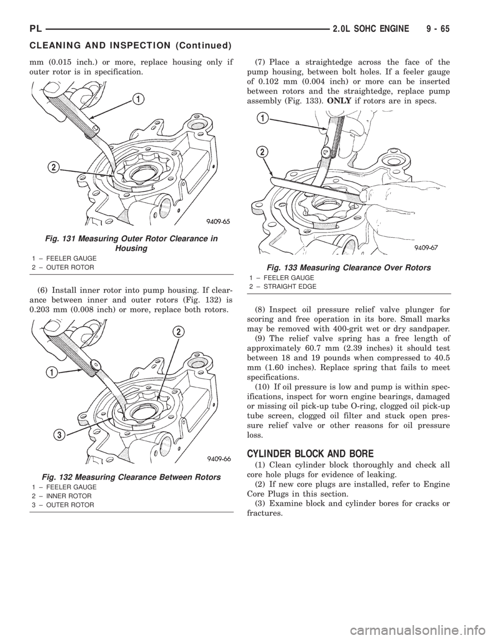
mm (0.015 inch.) or more, replace housing only if
outer rotor is in specification.
(6) Install inner rotor into pump housing. If clear-
ance between inner and outer rotors (Fig. 132) is
0.203 mm (0.008 inch) or more, replace both rotors.(7) Place a straightedge across the face of the
pump housing, between bolt holes. If a feeler gauge
of 0.102 mm (0.004 inch) or more can be inserted
between rotors and the straightedge, replace pump
assembly (Fig. 133).ONLYif rotors are in specs.
(8) Inspect oil pressure relief valve plunger for
scoring and free operation in its bore. Small marks
may be removed with 400-grit wet or dry sandpaper.
(9) The relief valve spring has a free length of
approximately 60.7 mm (2.39 inches) it should test
between 18 and 19 pounds when compressed to 40.5
mm (1.60 inches). Replace spring that fails to meet
specifications.
(10) If oil pressure is low and pump is within spec-
ifications, inspect for worn engine bearings, damaged
or missing oil pick-up tube O-ring, clogged oil pick-up
tube screen, clogged oil filter and stuck open pres-
sure relief valve or other reasons for oil pressure
loss.
CYLINDER BLOCK AND BORE
(1) Clean cylinder block thoroughly and check all
core hole plugs for evidence of leaking.
(2) If new core plugs are installed, refer to Engine
Core Plugs in this section.
(3) Examine block and cylinder bores for cracks or
fractures.
Fig. 131 Measuring Outer Rotor Clearance in
Housing
1 ± FEELER GAUGE
2 ± OUTER ROTOR
Fig. 132 Measuring Clearance Between Rotors
1 ± FEELER GAUGE
2 ± INNER ROTOR
3 ± OUTER ROTOR
Fig. 133 Measuring Clearance Over Rotors
1 ± FEELER GAUGE
2 ± STRAIGHT EDGE
PL2.0L SOHC ENGINE 9 - 65
CLEANING AND INSPECTION (Continued)
Page 791 of 1285
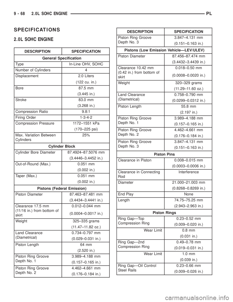
SPECIFICATIONS
2.0L SOHC ENGINE
DESCRIPTION SPECIFICATION
General Specification
Type In-Line OHV, SOHC
Number of Cylinders 4
Displacement 2.0 Liters
(122 cu. in.)
Bore 87.5 mm
(3.445 in.)
Stroke 83.0 mm
(3.268 in.)
Compression Ratio 9.8:1
Firing Order 1-3-4-2
Compression Pressure 1172±1551 kPa
(170±225 psi)
Max. Variation Between
Cylinders25%
Cylinder Block
Cylinder Bore Diameter 87.4924±87.5076 mm
(3.4446±3.4452 in.)
Out-of-Round (Max.) 0.051 mm
(0.002 in.)
Taper (Max.) 0.051 mm
(0.002 in.)
Pistons (Federal Emission)
Piston Diameter 87.463±87.481 mm
(3.4434±3.4441 in.)
Clearance 17.5 mm
(11/16 in.) from bottom of
skirt0.012±0.044 mm
(0.0004±0.0017 in.)
Weight 325±335 grams
(11.47±11.82 oz.)
Land Clearance
(Diametrical)0.734±0.797 mm
(0.029±0.031 in.)
Piston Length 64 mm
(2.520 in.)
Piston Ring Groove
Depth No. 13.989±4.188 mm
(0.157±0.165 in.)
Piston Ring Groove
Depth No. 24.462±4.661 mm
(0.176±0.184 in.)
DESCRIPTION SPECIFICATION
Piston Ring Groove
Depth No. 33.847±4.131 mm
(0.151±0.163 in.)
Pistons (Low Emission VehicleÐLEV/ULEV)
Piston Diameter 87.456±87.474 mm
(3.4432±3.4439 in.)
Clearance 10.42 mm
(0.42 in.) from bottom of
skirt0.018±0.50 mm
(0.0008±0.0020 in.)
Weight 320±329 grams
(11.29±11.60 oz.)
Land Clearance
(Diametrical)0.758±0.790 mm
(0.0299±0.0312 in.)
Piston Length 55.8 mm
(2.197 in.)
Piston Ring Groove
Depth No. 13.989±4.188 mm
(0.157±0.165 in.)
Piston Ring Groove
Depth No. 24.462±4.661 mm
(0.176±0.184 in.)
Piston Ring Groove
Depth No. 33.847±4.131 mm
(0.151±0.163 in.)
Piston Pins
Clearance in Piston 0.008±0.015 mm
(0.0003±0.0006 in.)
Clearance in Connecting
RodInterference
Diameter 21.000±21.003 mm
(0.8268±0.8269 in.)
End Play None
Length 74.75±75.25 mm
(2.943±2.963 in.)
Piston Rings
Ring GapÐTop
Compression Ring0.23±0.52 mm
(0.009±0.020 in.)
Wear Limit 0.8 mm
(0.031 in.)
Ring GapÐ2nd
Compression Ring0.49±0.78 mm
(0.019±0.031 in.)
Wear Limit 1.0 mm
(0.039 in.)
Ring GapÐOil Control
Steel Rails0.23±0.66 mm
(0.009±0.026 in.)
9 - 68 2.0L SOHC ENGINEPL
Page 834 of 1285
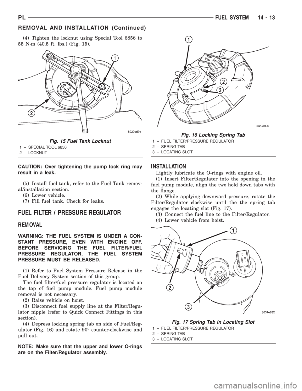
(4) Tighten the locknut using Special Tool 6856 to
55 N´m (40.5 ft. lbs.) (Fig. 15).
CAUTION: Over tightening the pump lock ring may
result in a leak.
(5) Install fuel tank, refer to the Fuel Tank remov-
al/installation section.
(6) Lower vehicle.
(7) Fill fuel tank. Check for leaks.
FUEL FILTER / PRESSURE REGULATOR
REMOVAL
WARNING: THE FUEL SYSTEM IS UNDER A CON-
STANT PRESSURE, EVEN WITH ENGINE OFF.
BEFORE SERVICING THE FUEL FILTER/FUEL
PRESSURE REGULATOR, THE FUEL SYSTEM
PRESSURE MUST BE RELEASED.
(1) Refer to Fuel System Pressure Release in the
Fuel Delivery System section of this group.
The fuel filter/fuel pressure regulator is located on
the top of fuel pump module. Fuel pump module
removal is not necessary.
(2) Raise vehicle on hoist.
(3) Disconnect fuel supply line at the Filter/Regu-
lator nipple (refer to Quick Connect Fittings in this
section).
(4) Depress locking spring tab on side of Fuel/Reg-
ulator (Fig. 16) and rotate 90É counter-clockwise and
pull out.
NOTE: Make sure that the upper and lower O-rings
are on the Filter/Regulator assembly.
INSTALLATION
Lightly lubricate the O-rings with engine oil.
(1) Insert Filter/Regulator into the opening in the
fuel pump module, align the two hold down tabs with
the flange.
(2) While applying downward pressure, rotate the
Filter/Regulator clockwise until the the spring tab
engages the locating slot (Fig. 17).
(3) Connect the fuel line to the Filter/Regulator.
(4) Lower vehicle from hoist.
Fig. 15 Fuel Tank Locknut
1 ± SPECIAL TOOL 6856
2 ± LOCKNUT
Fig. 16 Locking Spring Tab
1 ± FUEL FILTER/PRESSURE REGULATOR
2 ± SPRING TAB
3 ± LOCATING SLOT
Fig. 17 Spring Tab In Locating Slot
1 ± FUEL FILTER/PRESSURE REGULATOR
2 ± SPRING TAB
3 ± LOCATING SLOT
PLFUEL SYSTEM 14 - 13
REMOVAL AND INSTALLATION (Continued)
Page 844 of 1285
1 second. Therefore, battery voltage is not supplied to
the fuel pump, ignition coil, fuel injectors and heated
oxygen sensors.
ENGINE START-UP MODE
This is an OPEN LOOP mode. If the vehicle is in
park or neutral (automatic transaxles) or the clutch
pedal is depressed (manual transaxles) the ignition
switch energizes the starter relay. The following
actions occur when the starter motor is engaged.
²If the PCM receives the camshaft position sensor
and crankshaft position sensor signals, it energizes
the Auto Shutdown (ASD) relay and fuel pump relay.
If the PCM does not receive both signals within
approximately one second, it will not energize the
ASD relay and fuel pump relay. The ASD and fuel
pump relays supply battery voltage to the fuel pump,
fuel injectors, ignition coil and heated oxygen sen-
sors.
²The PCM energizes the injectors (on the 69É
degree falling edge) for a calculated pulse width until
it determines crankshaft position from the camshaft
position sensor and crankshaft position sensor sig-
nals. The PCM determines crankshaft position within
1 engine revolution.
²After determining crankshaft position, the PCM
begins energizing the injectors in sequence. It adjusts
injector pulse width and controls injector synchroni-
zation by turning the individual ground paths to the
injectors On and Off.
²When the engine idles within664 RPM of its
target RPM, the PCM compares current MAP sensor
value with the atmospheric pressure value received
during the Ignition Switch On (zero RPM) mode. If
the PCM does not detect a minimum difference
between the two values, it sets a MAP diagnostic
trouble code into memory.
Once the ASD and fuel pump relays have been
energized, the PCM determines injector pulse width
based on the following:
²Battery voltage
²Engine coolant temperature
²Engine RPM
²Intake air temperature (IAT)
²Throttle position
²The number of engine revolutions since cranking
was initiated.
During Start-up the PCM maintains ignition tim-
ing at 9É BTDC.
ENGINE WARM-UP MODE
This is an OPEN LOOP mode. The following inputs
are received by the PCM:
²Engine coolant temperature
²Manifold Absolute Pressure (MAP)
²Intake air temperature (IAT)²Crankshaft position (engine speed)
²Camshaft position
²Knock sensor
²Throttle position
²A/C switch
²Battery voltage
²Power steering pressure switch
²Vehicle speed
²Speed control
²O2 sensors
²All diagnostics
The PCM adjusts injector pulse width and controls
injector synchronization by turning the individual
ground paths to the injectors On and Off.
The PCM adjusts ignition timing and engine idle
speed. Engine idle speed is adjusted through the idle
air control motor.
CRUISE OR IDLE MODE
When the engine is at operating temperature this
is a CLOSED LOOP mode. During cruising or idle
the following inputs are received by the PCM:
²Intake air temperature
²Engine coolant temperature
²Manifold absolute pressure
²Crankshaft position (engine speed)
²Camshaft position
²Knock sensor
²Throttle position
²Exhaust gas oxygen content
²A/C control positions
²Power steering pressure switch
²Battery voltage
²Vehicle speed
The PCM adjusts injector pulse width and controls
injector synchronization by turning the individual
ground paths to the injectors On and Off.
The PCM adjusts engine idle speed and ignition
timing. The PCM adjusts the air/fuel ratio according
to the oxygen content in the exhaust gas (measured
by the upstream and downstream heated oxygen sen-
sor).
The PCM monitors for engine misfire. During
active misfire and depending on the severity, the
PCM either continuously illuminates or flashes the
malfunction indicator lamp (Check Engine light on
instrument panel). Also, the PCM stores an engine
misfire DTC in memory.
The PCM performs several diagnostic routines.
They include:
²Oxygen sensor monitor
²Downstream heated oxygen sensor diagnostics
during open loop operation (except for shorted)
²Fuel system monitor
²EGR monitor
²Purge system monitor
PLFUEL SYSTEM 14 - 23
DESCRIPTION AND OPERATION (Continued)
Page 846 of 1285
²Air Conditioning Controls
²Battery Voltage
²Inlet Air/Battery Temperature Sensor
²Brake Switch
²Camshaft Position Sensor
²Crankshaft Position Sensor
²Engine Coolant Temperature Sensor
²Fuel Level Sensor
²Ignition Switch
²Inlet Air/Intake Air Temperature Sensor
²Knock Sensor
²Manifold Absolute Pressure (MAP) Sensor
²Oxygen Sensors
²Power Steering Pressure Switch²SCI Receive
²Speed Control Switches
²Throttle Position Sensor
²Transmission Park/Neutral Switch (automatic
transmission)
²Vehicle Speed Sensor
PCM Outputs:
²Air Conditioning WOT Relay
²Auto Shutdown (ASD) Relay
²Charging Indicator Lamp
²Data Link Connector
²Proportional Purge Solenoid
²EGR Solenoid
²Fuel Injectors
²Fuel Pump Relay
²Generator Field
²Idle Air Control Motor
²Ignition Coils
²Malfunction Indicator (Check Engine) Lamp
²Radiator Fan Relay
²Speed Control Solenoids
²Tachometer
²Torque Convertor Clutch Solenoid
Based on inputs it receives, the PCM adjusts fuel
injector pulse width, idle speed, ignition spark
advance, ignition coil dwell and EVAP canister purge
operation. The PCM regulates the cooling fan, air
conditioning and speed control systems. The PCM
changes generator charge rate by adjusting the gen-
erator field. The PCM also performs diagnostics.
The PCM adjusts injector pulse width (air-fuel
ratio) based on the following inputs.
²Battery voltage
²Coolant temperature
²Inlet Air/Intake air temperature
²Exhaust gas content (oxygen sensor)
²Engine speed (crankshaft position sensor)
²Manifold absolute pressure
²Throttle position
The PCM adjusts ignition timing based on the fol-
lowing inputs.
²Coolant temperature
²Inlet Air/Intake air temperature
²Engine speed (crankshaft position sensor)
²Knock sensor
²Manifold absolute pressure
²Throttle position
²Transmission gear selection (park/neutral
switch)
The PCM also adjusts engine idle speed through
the idle air control motor based on the following
inputs.
²Air conditioning sense
²Battery voltage
²Battery temperature
²Brake switch
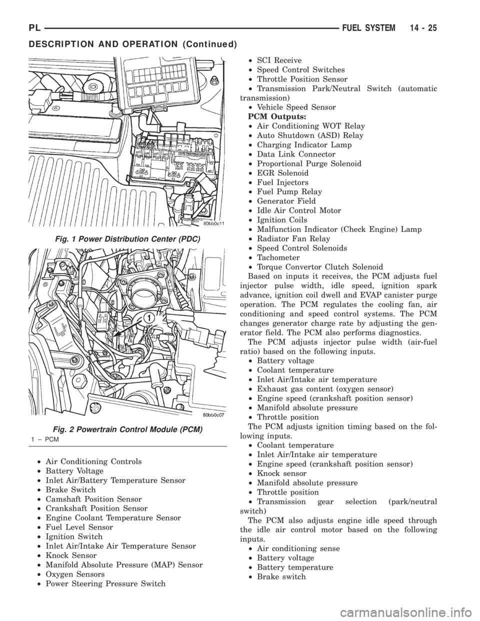
Fig. 1 Power Distribution Center (PDC)
Fig. 2 Powertrain Control Module (PCM)
1 ± PCM
PLFUEL SYSTEM 14 - 25
DESCRIPTION AND OPERATION (Continued)