2000 DODGE NEON warning light
[x] Cancel search: warning lightPage 454 of 1285
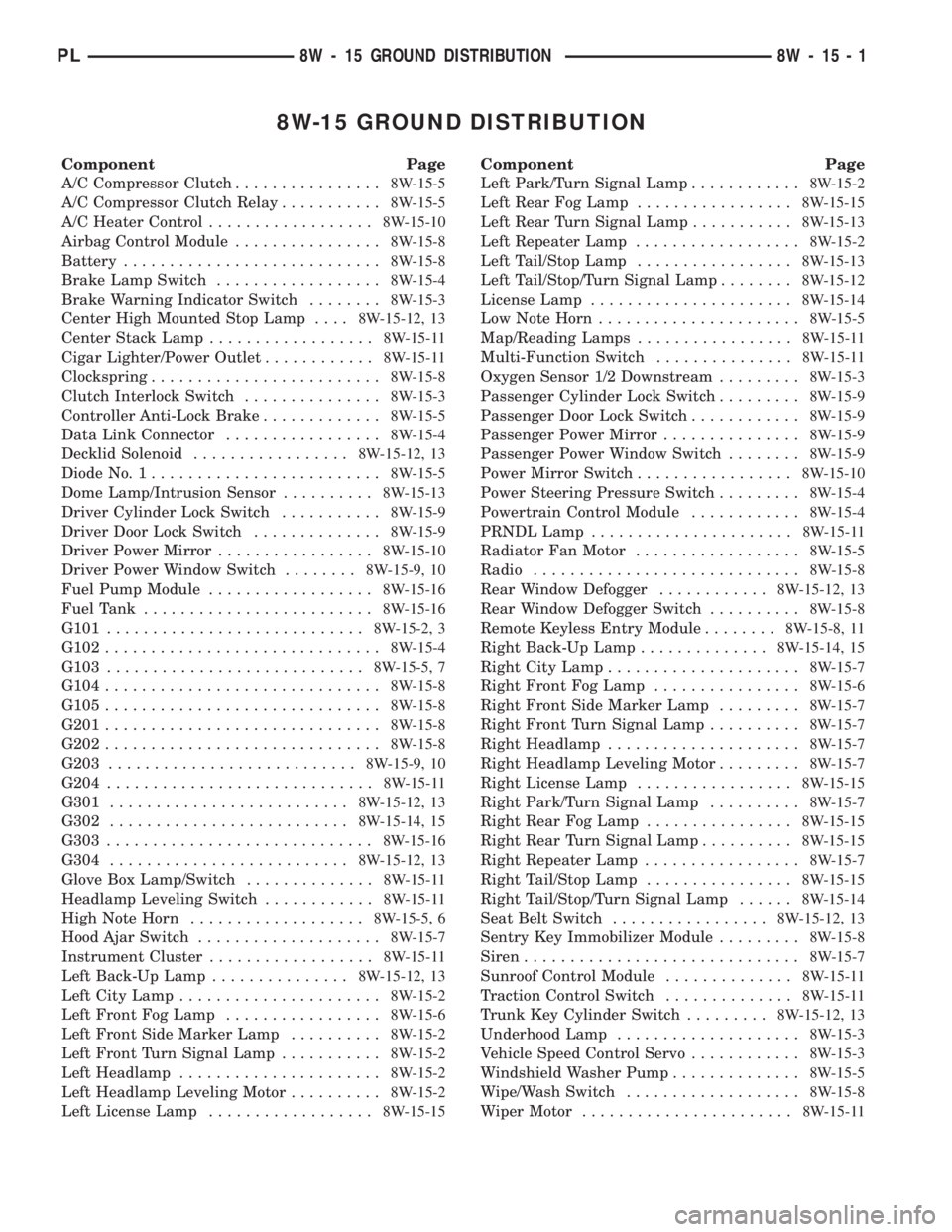
8W-15 GROUND DISTRIBUTION
Component Page
A/C Compressor Clutch................8W-15-5
A/C Compressor Clutch Relay...........8W-15-5
A/C Heater Control..................8W-15-10
Airbag Control Module................8W-15-8
Battery............................8W-15-8
Brake Lamp Switch..................8W-15-4
Brake Warning Indicator Switch........8W-15-3
Center High Mounted Stop Lamp....8W-15-12, 13
Center Stack Lamp..................8W-15-11
Cigar Lighter/Power Outlet............8W-15-11
Clockspring.........................8W-15-8
Clutch Interlock Switch...............8W-15-3
Controller Anti-Lock Brake.............8W-15-5
Data Link Connector.................8W-15-4
Decklid Solenoid.................8W-15-12, 13
Diode No. 1.........................8W-15-5
Dome Lamp/Intrusion Sensor..........8W-15-13
Driver Cylinder Lock Switch...........8W-15-9
Driver Door Lock Switch..............8W-15-9
Driver Power Mirror.................8W-15-10
Driver Power Window Switch........8W-15-9, 10
Fuel Pump Module..................8W-15-16
Fuel Tank.........................8W-15-16
G101............................8W-15-2, 3
G102..............................8W-15-4
G103............................8W-15-5, 7
G104..............................8W-15-8
G105..............................8W-15-8
G201..............................8W-15-8
G202..............................8W-15-8
G203...........................8W-15-9, 10
G204.............................8W-15-11
G301..........................8W-15-12, 13
G302..........................8W-15-14, 15
G303.............................8W-15-16
G304..........................8W-15-12, 13
Glove Box Lamp/Switch..............8W-15-11
Headlamp Leveling Switch............8W-15-11
High Note Horn...................8W-15-5, 6
Hood Ajar Switch....................8W-15-7
Instrument Cluster..................8W-15-11
Left Back-Up Lamp...............8W-15-12, 13
Left City Lamp......................8W-15-2
Left Front Fog Lamp.................8W-15-6
Left Front Side Marker Lamp..........8W-15-2
Left Front Turn Signal Lamp...........8W-15-2
Left Headlamp......................8W-15-2
Left Headlamp Leveling Motor..........8W-15-2
Left License Lamp..................8W-15-15Component Page
Left Park/Turn Signal Lamp............8W-15-2
Left Rear Fog Lamp.................8W-15-15
Left Rear Turn Signal Lamp...........8W-15-13
Left Repeater Lamp..................8W-15-2
Left Tail/Stop Lamp.................8W-15-13
Left Tail/Stop/Turn Signal Lamp........8W-15-12
License Lamp......................8W-15-14
Low Note Horn......................8W-15-5
Map/Reading Lamps.................8W-15-11
Multi-Function Switch...............8W-15-11
Oxygen Sensor 1/2 Downstream.........8W-15-3
Passenger Cylinder Lock Switch.........8W-15-9
Passenger Door Lock Switch............8W-15-9
Passenger Power Mirror...............8W-15-9
Passenger Power Window Switch........8W-15-9
Power Mirror Switch.................8W-15-10
Power Steering Pressure Switch.........8W-15-4
Powertrain Control Module............8W-15-4
PRNDL Lamp......................8W-15-11
Radiator Fan Motor..................8W-15-5
Radio.............................8W-15-8
Rear Window Defogger............8W-15-12, 13
Rear Window Defogger Switch..........8W-15-8
Remote Keyless Entry Module........8W-15-8, 11
Right Back-Up Lamp..............8W-15-14, 15
Right City Lamp.....................8W-15-7
Right Front Fog Lamp................8W-15-6
Right Front Side Marker Lamp.........8W-15-7
Right Front Turn Signal Lamp..........8W-15-7
Right Headlamp.....................8W-15-7
Right Headlamp Leveling Motor.........8W-15-7
Right License Lamp.................8W-15-15
Right Park/Turn Signal Lamp..........8W-15-7
Right Rear Fog Lamp................8W-15-15
Right Rear Turn Signal Lamp..........8W-15-15
Right Repeater Lamp.................8W-15-7
Right Tail/Stop Lamp................8W-15-15
Right Tail/Stop/Turn Signal Lamp......8W-15-14
Seat Belt Switch.................8W-15-12, 13
Sentry Key Immobilizer Module.........8W-15-8
Siren..............................8W-15-7
Sunroof Control Module..............8W-15-11
Traction Control Switch..............8W-15-11
Trunk Key Cylinder Switch.........8W-15-12, 13
Underhood Lamp....................8W-15-3
Vehicle Speed Control Servo............8W-15-3
Windshield Washer Pump..............8W-15-5
Wipe/Wash Switch...................8W-15-8
Wiper Motor.......................8W-15-11
PL8W - 15 GROUND DISTRIBUTION 8W - 15 - 1
Page 610 of 1285
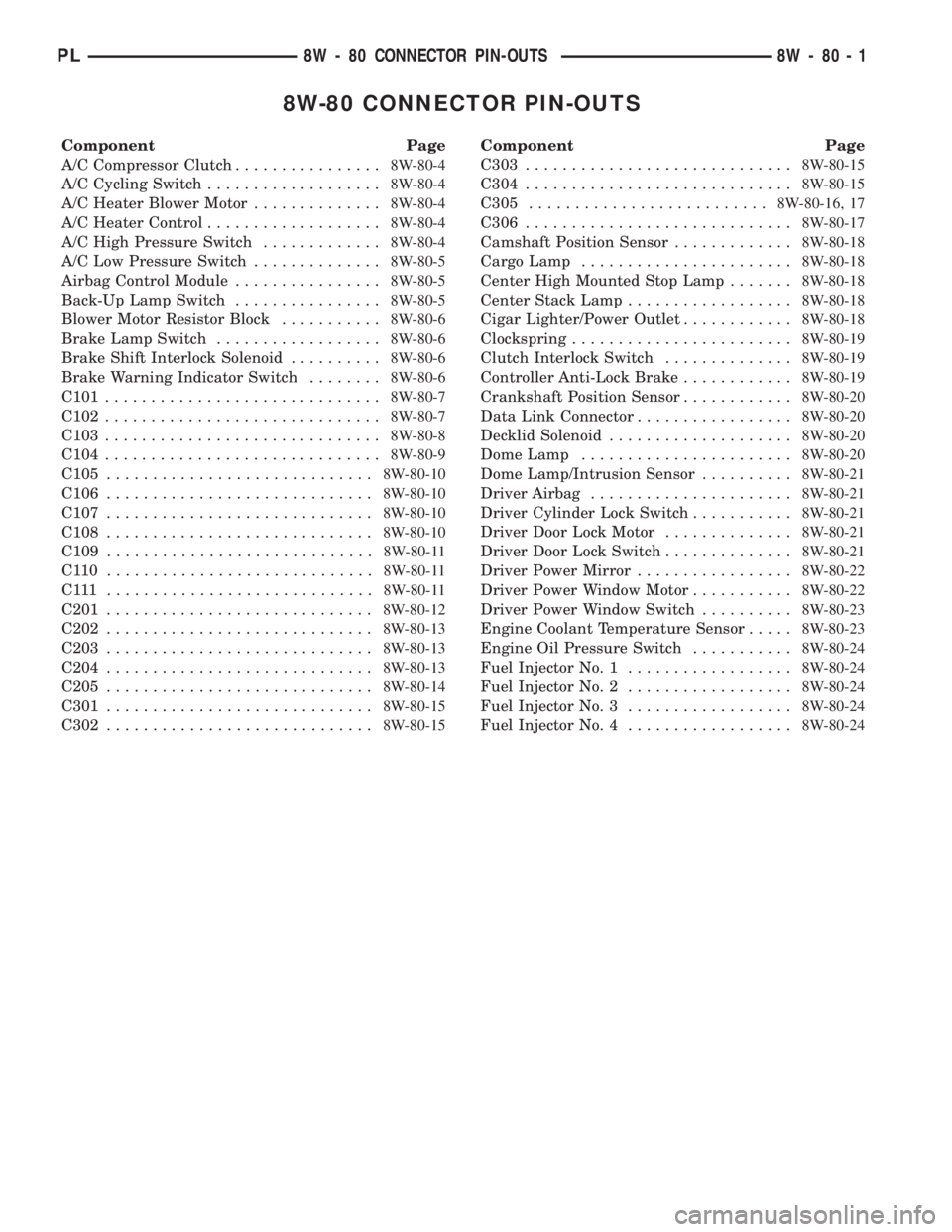
8W-80 CONNECTOR PIN-OUTS
Component Page
A/C Compressor Clutch................8W-80-4
A/C Cycling Switch...................8W-80-4
A/C Heater Blower Motor..............8W-80-4
A/C Heater Control...................8W-80-4
A/C High Pressure Switch.............8W-80-4
A/C Low Pressure Switch..............8W-80-5
Airbag Control Module................8W-80-5
Back-Up Lamp Switch................8W-80-5
Blower Motor Resistor Block...........8W-80-6
Brake Lamp Switch..................8W-80-6
Brake Shift Interlock Solenoid..........8W-80-6
Brake Warning Indicator Switch........8W-80-6
C101..............................8W-80-7
C102..............................8W-80-7
C103..............................8W-80-8
C104..............................8W-80-9
C105.............................8W-80-10
C106.............................8W-80-10
C107.............................8W-80-10
C108.............................8W-80-10
C109.............................8W-80-11
C110 .............................8W-80-11
C111 .............................8W-80-11
C201.............................8W-80-12
C202.............................8W-80-13
C203.............................8W-80-13
C204.............................8W-80-13
C205.............................8W-80-14
C301.............................8W-80-15
C302.............................8W-80-15Component Page
C303.............................8W-80-15
C304.............................8W-80-15
C305..........................8W-80-16, 17
C306.............................8W-80-17
Camshaft Position Sensor.............8W-80-18
Cargo Lamp.......................8W-80-18
Center High Mounted Stop Lamp.......8W-80-18
Center Stack Lamp..................8W-80-18
Cigar Lighter/Power Outlet............8W-80-18
Clockspring........................8W-80-19
Clutch Interlock Switch..............8W-80-19
Controller Anti-Lock Brake............8W-80-19
Crankshaft Position Sensor............8W-80-20
Data Link Connector.................8W-80-20
Decklid Solenoid....................8W-80-20
Dome Lamp.......................8W-80-20
Dome Lamp/Intrusion Sensor..........8W-80-21
Driver Airbag......................8W-80-21
Driver Cylinder Lock Switch...........8W-80-21
Driver Door Lock Motor..............8W-80-21
Driver Door Lock Switch..............8W-80-21
Driver Power Mirror.................8W-80-22
Driver Power Window Motor...........8W-80-22
Driver Power Window Switch..........8W-80-23
Engine Coolant Temperature Sensor.....8W-80-23
Engine Oil Pressure Switch...........8W-80-24
Fuel Injector No. 1..................8W-80-24
Fuel Injector No. 2..................8W-80-24
Fuel Injector No. 3..................8W-80-24
Fuel Injector No. 4..................8W-80-24
PL8W - 80 CONNECTOR PIN-OUTS 8W - 80 - 1
Page 830 of 1285
INSTALLATION
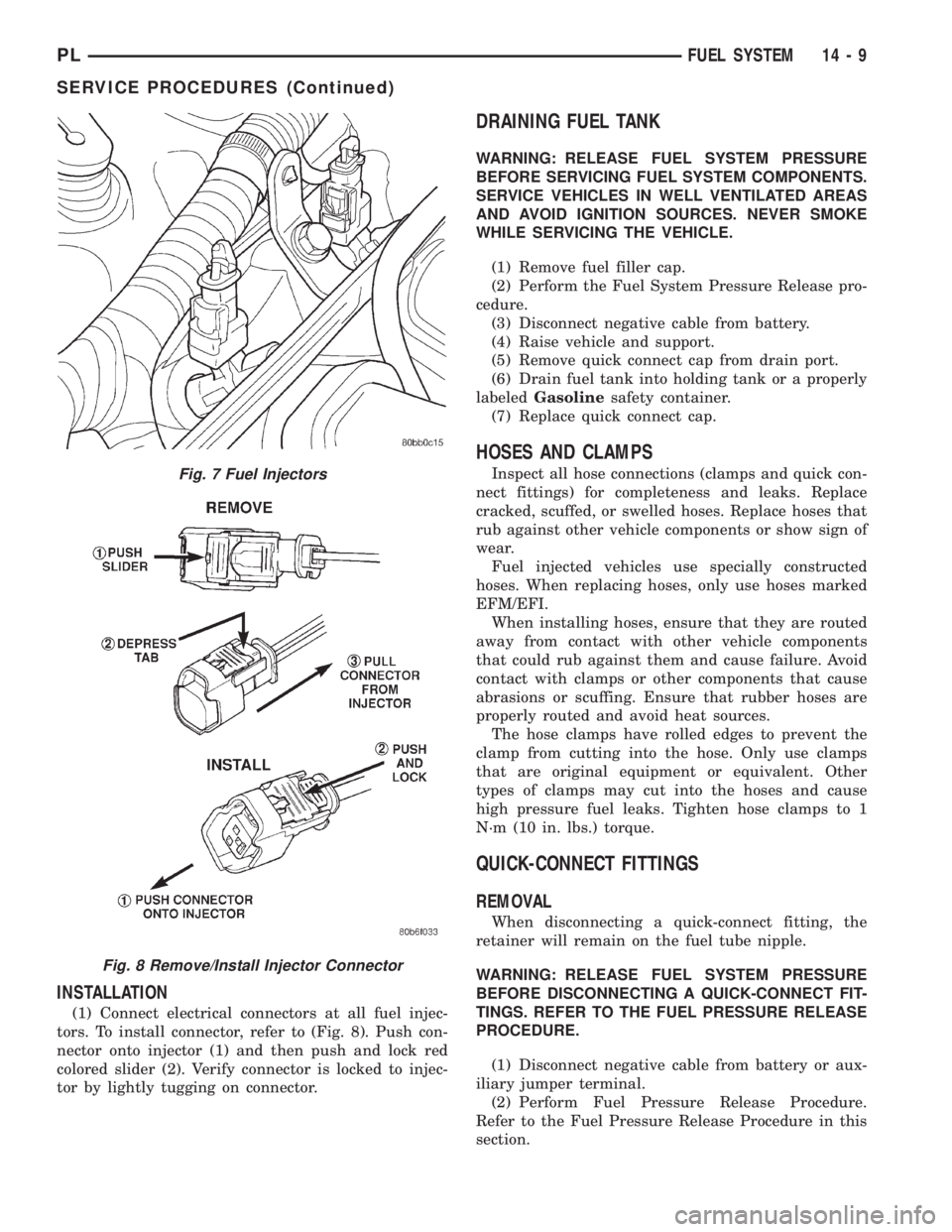
(1) Connect electrical connectors at all fuel injec-
tors. To install connector, refer to (Fig. 8). Push con-
nector onto injector (1) and then push and lock red
colored slider (2). Verify connector is locked to injec-
tor by lightly tugging on connector.
DRAINING FUEL TANK
WARNING: RELEASE FUEL SYSTEM PRESSURE
BEFORE SERVICING FUEL SYSTEM COMPONENTS.
SERVICE VEHICLES IN WELL VENTILATED AREAS
AND AVOID IGNITION SOURCES. NEVER SMOKE
WHILE SERVICING THE VEHICLE.
(1) Remove fuel filler cap.
(2) Perform the Fuel System Pressure Release pro-
cedure.
(3) Disconnect negative cable from battery.
(4) Raise vehicle and support.
(5) Remove quick connect cap from drain port.
(6) Drain fuel tank into holding tank or a properly
labeledGasolinesafety container.
(7) Replace quick connect cap.
HOSES AND CLAMPS
Inspect all hose connections (clamps and quick con-
nect fittings) for completeness and leaks. Replace
cracked, scuffed, or swelled hoses. Replace hoses that
rub against other vehicle components or show sign of
wear.
Fuel injected vehicles use specially constructed
hoses. When replacing hoses, only use hoses marked
EFM/EFI.
When installing hoses, ensure that they are routed
away from contact with other vehicle components
that could rub against them and cause failure. Avoid
contact with clamps or other components that cause
abrasions or scuffing. Ensure that rubber hoses are
properly routed and avoid heat sources.
The hose clamps have rolled edges to prevent the
clamp from cutting into the hose. Only use clamps
that are original equipment or equivalent. Other
types of clamps may cut into the hoses and cause
high pressure fuel leaks. Tighten hose clamps to 1
N´m (10 in. lbs.) torque.
QUICK-CONNECT FITTINGS
REMOVAL
When disconnecting a quick-connect fitting, the
retainer will remain on the fuel tube nipple.
WARNING: RELEASE FUEL SYSTEM PRESSURE
BEFORE DISCONNECTING A QUICK-CONNECT FIT-
TINGS. REFER TO THE FUEL PRESSURE RELEASE
PROCEDURE.
(1) Disconnect negative cable from battery or aux-
iliary jumper terminal.
(2) Perform Fuel Pressure Release Procedure.
Refer to the Fuel Pressure Release Procedure in this
section.
Fig. 7 Fuel Injectors
Fig. 8 Remove/Install Injector Connector
PLFUEL SYSTEM 14 - 9
SERVICE PROCEDURES (Continued)
Page 834 of 1285
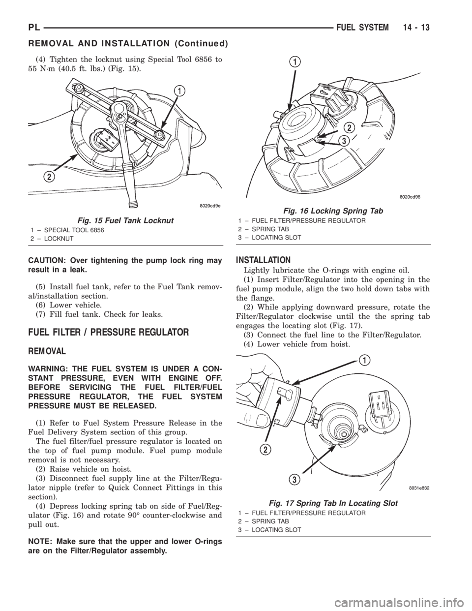
(4) Tighten the locknut using Special Tool 6856 to
55 N´m (40.5 ft. lbs.) (Fig. 15).
CAUTION: Over tightening the pump lock ring may
result in a leak.
(5) Install fuel tank, refer to the Fuel Tank remov-
al/installation section.
(6) Lower vehicle.
(7) Fill fuel tank. Check for leaks.
FUEL FILTER / PRESSURE REGULATOR
REMOVAL
WARNING: THE FUEL SYSTEM IS UNDER A CON-
STANT PRESSURE, EVEN WITH ENGINE OFF.
BEFORE SERVICING THE FUEL FILTER/FUEL
PRESSURE REGULATOR, THE FUEL SYSTEM
PRESSURE MUST BE RELEASED.
(1) Refer to Fuel System Pressure Release in the
Fuel Delivery System section of this group.
The fuel filter/fuel pressure regulator is located on
the top of fuel pump module. Fuel pump module
removal is not necessary.
(2) Raise vehicle on hoist.
(3) Disconnect fuel supply line at the Filter/Regu-
lator nipple (refer to Quick Connect Fittings in this
section).
(4) Depress locking spring tab on side of Fuel/Reg-
ulator (Fig. 16) and rotate 90É counter-clockwise and
pull out.
NOTE: Make sure that the upper and lower O-rings
are on the Filter/Regulator assembly.
INSTALLATION
Lightly lubricate the O-rings with engine oil.
(1) Insert Filter/Regulator into the opening in the
fuel pump module, align the two hold down tabs with
the flange.
(2) While applying downward pressure, rotate the
Filter/Regulator clockwise until the the spring tab
engages the locating slot (Fig. 17).
(3) Connect the fuel line to the Filter/Regulator.
(4) Lower vehicle from hoist.
Fig. 15 Fuel Tank Locknut
1 ± SPECIAL TOOL 6856
2 ± LOCKNUT
Fig. 16 Locking Spring Tab
1 ± FUEL FILTER/PRESSURE REGULATOR
2 ± SPRING TAB
3 ± LOCATING SLOT
Fig. 17 Spring Tab In Locating Slot
1 ± FUEL FILTER/PRESSURE REGULATOR
2 ± SPRING TAB
3 ± LOCATING SLOT
PLFUEL SYSTEM 14 - 13
REMOVAL AND INSTALLATION (Continued)
Page 888 of 1285
reduces the power required to drive the pump and
holds down temperature build-up.
When steering conditions exceed maximum pres-
sure requirements, such as when the wheels are
turned against the stops, the pressure built up in the
steering gear exerts pressure on the spring end of the
flow control valve. The high pressure lifts the relief
valve ball from its seat and allows oil to flow through
a trigger orifice located in the outlet fitting. This
reduces pressure on the spring end of the flow con-
trol valve which then opens and allows the oil to
return to the intake side of the pump. This action
limits maximum pressure output of the pump to a
safe level.
Under normal power steering pump operating con-
ditions, pressure requirements of the pump are below
maximum, causing the pressure relief valve to
remain closed.
POWER STEERING FLUID RESERVOIR
The power steering fluid reservoir is mounted on
the power steering pump using 3 bolts (Fig. 1). It
stores fluid for the power steering system.
The power steering fluid reservoir is considered an
integral part of the power steering pump and is not
serviced separately.
SERVICE PROCEDURES
POWER STEERING PUMP INITIAL OPERATION
CAUTION: The fluid level should be checked with
engine off to prevent injury from moving compo-
nents. Use only MoparTPower Steering Fluid. Do
not use automatic transmission fluid. Do not over-
fill.
Wipe the filler cap clean, then check the fluid level.
The dipstick should indicateCOLDwhen the fluid is
at normal temperature, approximately 21ÉC to 27ÉC
(70ÉF to 80ÉF).
(1) Fill the power steering fluid reservoir to the
proper level and let the fluid settle for at least two
minutes.
(2) Start the engine and let run for a few seconds,
then turn the engine off.
(3) Add fluid if necessary. Repeat the above proce-
dure until the fluid level remains constant after run-
ning the engine.
(4) Raise the front wheels off the ground.
(5) Start the engine. Slowly turn the steering
wheel right and left, lightly contacting the wheel
stops.
(6) Add power steering fluid if necessary.
(7) Lower the vehicle and turn the steering wheel
slowly from lock to lock.(8) Stop the engine. Check the fluid level and refill
as required.
(9) If the fluid is extremely foamy, allow the vehi-
cle to stand a few minutes and repeat the above pro-
cedure.
REMOVAL AND INSTALLATION
SERVICE WARNINGS AND CAUTIONS
WARNING: POWER STEERING FLUID, ENGINE
PARTS AND EXHAUST SYSTEM MAY BE
EXTREMELY HOT IF ENGINE HAS BEEN RUNNING.
DO NOT START ENGINE WITH ANY LOOSE OR DIS-
CONNECTED HOSES. DO NOT ALLOW HOSES TO
TOUCH HOT EXHAUST MANIFOLD OR CATALYST.
WARNING: FLUID LEVEL SHOULD BE CHECKED
WITH THE ENGINE OFF TO PREVENT PERSONAL
INJURY FROM MOVING PARTS.
CAUTION: When the system is open, cap all open
ends of the hoses, power steering pump fittings or
power steering gear ports to prevent entry of for-
eign material into the components.
NOTE: Do not use any type of automatic transmis-
sion fluid in the power steering system.
POWER STEERING PUMP
NOTE: Before proceeding with this removal and
installation procedure, review SERVICE WARNINGS
AND CAUTIONS at the beginning of REMOVAL AND
INSTALLATION in this section.
REMOVAL
(1) Remove battery cable from the negative post on
the battery.
(2) Siphon as much fluid as possible from the
power steering fluid reservoir.
(3) Remove the power steering pump drive belt
from the power steering pump pulley. Refer to
ACCESSORY DRIVE BELTS in the COOLING SYS-
TEM service manual group for the required removal
and installation procedure.
(4) Remove the hose clamp securing the return
hose to the power steering fluid reservoir. Slide the
hose off the end of the reservoir fitting. (Fig. 2).
(5) Back out the tube nut securing the power
steering fluid pressure hose to the power steering
pump and remove the hose from the pump (Fig. 2).
PLSTEERING 19 - 17
DESCRIPTION AND OPERATION (Continued)
Page 908 of 1285
bolt nut to a torque of 28 N´m (250 in. lbs.). Install
the pinch bolt retainer pin.
(11) Install the upper and lower steering column
shrouds onto the steering column (Fig. 9). Snap the
two shrouds together and then install and tighten
the two screws securing the shrouds to the column.
(12) Install the steering column cover that mounts
below the steering column on the instrument panel
by first aligning the retainer clips and snapping the
cover into place. Install the two screws along the bot-
tom of the steering column cover.
(13) Align the clips along the outer edge of the
instrument cluster bezel with the mounting holes in
the instrument panel and install the bezel.
(14) Align the clips on the bottom of the instru-
ment panel top cover with the mounting holes in the
instrument panel and install the top cover by push-
ing it down into place.
(15) Install the screw securing the left end of the
top cover to the instrument panel.
CAUTION: If there is any question as to whether
the clockspring is in the centered position, the
clock spring needs to be recentered before install-
ing the steering wheel. If the clockspring is not cen-
tered, it may be overextended, causing the
clockspring to become inoperative.
(16) Center the clockspring using the following
procedure:
²Using your fingers, rotate the clockspring rotor
in the CLOCKWISE DIRECTION to the end of the
travel. Do not apply excessive torque.
²From the end of travel, rotate the rotor two full
turns and an additional half turn in the counter-
clockwise direction. (The wires should end up at the
bottom of the clockspring).
CAUTION: Do not install the steering wheel onto
the shaft of the steering column by driving it onto
the shaft.
(17) Feed the clockspring wiring leads through the
hole in the steering wheel (Fig. 6). Align the steering
wheel's wide mounting spline with the steering col-
umn shaft missing spline area and push the wheel
onto the shaft. Make sure the clockspring squares up
with the back of the wheel and does not bind.
(18) Install the steering wheel retaining nut and
tighten it until the steering wheel is fully installed
on shaft. Tighten the steering wheel retaining nut to
a torque of 61 N´m (45 ft. lbs.).
(19) Connect the clockspring electrical leads to the
speed control switches and reinstall the switches on
the steering wheel (Fig. 6).
(20) Install the airbag electrical lead from the
clockspring into the connector on the back of the air-bag module (Fig. 6). Be sure electrical connector from
clockspring is securely latched into airbag module
connector.
(21) Connect the horn switch electrical lead to the
connector on the back of the airbag module (Fig. 6).
CAUTION: The fasteners originally used for the air-
bag components are specifically designed for the
airbag system. They must never be replaced with
any substitutes. Anytime a new fastener is needed,
replace it with only the correct fastener listed in the
parts book.
(22) Install the airbag module into the center of
the steering wheel. Align the airbag module mount-
ing holes with the bolt holes in steering wheel (Fig.
6). Install only the two original or identical replace-
ment airbag module mounting screws. Tighten the
two air bag module attaching bolts to a torque of 10
N´m (90 in. lbs.).
(23) Install the airbag mounting screw trim caps
on the steering wheel rear cover (Fig. 7). One belongs
on each side of the steering wheel.
NOTE: When reconnecting the battery on a vehicle
that has had the airbag module removed, the fol-
lowing procedure should be used.
(24) Reconnect the ground cable to the negative
post of the battery in the following manor:
²Connect a scan tool (DRBIIIt) to the data link
diagnostic connector located below the steering col-
umn.
²Turn the ignition key to the ON position. Exit
the vehicle with the scan tool leaving the scan tool
harness plugged in.
²Ensuring that there are no occupants in the
vehicle, connect the ground (-) cable to the negative
post of the battery.
²Using the scan tool, read and record any fault
codes. Refer to the DRIVER AND PASSENGER AIR-
BAG SYSTEM diagnostic manual if any faults are
found.
²Erase any stored faults if there are no active
fault codes. If a problem exists, the fault code will
not erase.
²Reach around the back of the steering wheel (in
front of the instrument cluster) and turn the ignition
key to OFF, then back ON while observing the
instrument cluster airbag lamp. It should go on for
six to eight seconds, then go out. This will indicate
that the airbag system is functioning normally. If air-
bag warning lamp fails to light, blinks on and off, or
goes on and stays on, there is an airbag system mal-
function. Refer to the BODY DIAGNOSTIC PROCE-
DURES manual to diagnose the system malfunction.
PLSTEERING 19 - 37
REMOVAL AND INSTALLATION (Continued)
Page 1135 of 1285
DIAGNOSIS AND TESTING
WATER LEAKS
Water leaks can be caused by poor sealing,
improper body component alignment, body seam
porosity, missing plugs, or blocked drain holes. Cen-
trifugal and gravitational force can cause water to
drip from a location away from the actual leak point,
making leak detection difficult. All body sealing
points should be water tight in normal wet-driving
conditions. Water flowing downward from the front of
the vehicle should not enter the passenger or luggage
compartment. Moving sealing surfaces will not
always seal water tight under all conditions. At
times, side glass or door seals will allow water to
enter the passenger compartment during high pres-
sure washing or hard driving rain (severe) condi-
tions. Overcompensating on door or glass
adjustments to stop a water leak that occurs under
severe conditions can cause premature seal wear and
excessive closing or latching effort. After completing
a repair, water-test vehicle to verify leak has stopped
before returning vehicle to use.
VISUAL INSPECTION BEFORE WATER LEAK TESTS
Verify that floor and body plugs are in place, body
drains are clear, and body components are properly
aligned and sealed. If component alignment or seal-
ing is necessary, refer to the appropriate section of
this group for proper procedures.
WATER LEAK TESTS
WARNING: DO NOT USE ELECTRIC SHOP LIGHTS
OR TOOLS IN WATER TEST AREA. PERSONAL
INJURY CAN RESULT.
When the conditions causing a water leak have
been determined, simulate the conditions as closely
as possible.
²If a leak occurs with the vehicle parked in a
steady light rain, flood the leak area with an open-
ended garden hose.
²If a leak occurs while driving at highway speeds
in a steady rain, test the leak area with a reasonable
velocity stream or fan spray of water. Direct the
spray in a direction comparable to actual conditions.
²If a leak occurs when the vehicle is parked on an
incline, hoist the end or side of the vehicle to simu-
late this condition. This method can be used when
the leak occurs when the vehicle accelerates, stops or
turns. If the leak occurs on acceleration, hoist the
front of the vehicle. If the leak occurs when braking,
hoist the back of the vehicle. If the leak occurs on left
turns, hoist the left side of the vehicle. If the leak
occurs on right turns, hoist the right side of the vehi-cle. For hoisting recommendations refer to Group 0,
Lubrication and Maintenance, General Information
section.
WATER LEAK DETECTION
To detect a water leak point-of-entry, do a water
test and watch for water tracks or droplets forming
on the inside of the vehicle. If necessary, remove inte-
rior trim covers or panels to gain visual access to the
leak area. If the hose cannot be positioned without
being held, have someone help do the water test.
Some water leaks must be tested for a considerable
length of time to become apparent. When a leak
appears, find the lowest point of the water track or
drop. After leak point has been found, repair the leak
and water test to verify that the leak has stopped.
Locating the entry point of water that is leaking
into a cavity between panels can be difficult. The
trapped water may splash or run from the cavity,
often at a distance from the entry point. Most water
leaks of this type become apparent after accelerating,
stopping, turning, or when on an incline.
MIRROR INSPECTION METHOD
When a leak point area is visually obstructed, use
a suitable mirror to gain visual access. A mirror can
also be used to deflect light to a limited-access area
to assist in locating a leak point.
BRIGHT LIGHT LEAK TEST METHOD
Some water leaks in the luggage compartment can
be detected without water testing. Position the vehi-
cle in a brightly lit area. From inside the darkened
luggage compartment inspect around seals and body
seams. If necessary, have a helper direct a drop light
over the suspected leak areas around the luggage
compartment. If light is visible through a normally
sealed location, water could enter through the open-
ing.
PRESSURIZED LEAK TEST METHOD
When a water leak into the passenger compart-
ment cannot be detected by water testing, pressurize
the passenger compartment and soap test exterior of
the vehicle. To pressurize the passenger compart-
ment, close all doors and windows, start engine, and
set heater control to high blower in HEAT position. If
engine can not be started, connect a charger to the
battery to ensure adequate voltage to the blower.
With interior pressurized, apply dish detergent solu-
tion to suspected leak area on the exterior of the
vehicle. Apply detergent solution with spray device or
soft bristle brush. If soap bubbles occur at a body
seam, joint, seal or gasket, the leak entry point could
be at that location.
23 - 18 BODYPL
Page 1137 of 1285
SAFETY PRECAUTION AND WARNINGS
WARNING: EYE PROTECTION SHOULD BE USED
WHEN SERVICING RTM AND SMC COMPONENTS.
PERSONAL INJURE CAN RESULT.
USE AN OSHA APPROVED BREATHING DEVICE
WHEN MIXING EPOXY, GRINDING RTM AND SMC,
AND SPRAYING PAINT OR SOLVENTS IN A CON-
FINED AREA. PERSONAL INJURY CAN RESULT.
AVOID PROLONGED SKIN CONTACT WITH
EPOXY RESIN, PETROLEUM, OR ALCOHOL BASED
SOLVENTS. PERSONAL INJURY CAN RESULT.
DO NOT VENTURE UNDER A HOISTED VEHICLE
THAT IS NOT PROPERLY SUPPORTED ON SAFETY
STANDS. PERSONAL INJURY CAN RESULT.
²When holes must be drilled or cut in body pan-
els, verify locations of internal body components and
electrical wiring. Damage to vehicle can result.
²Do not use abrasive chemicals or compounds on
undamaged painted surfaces around repair areas.
Damage to finish can result.
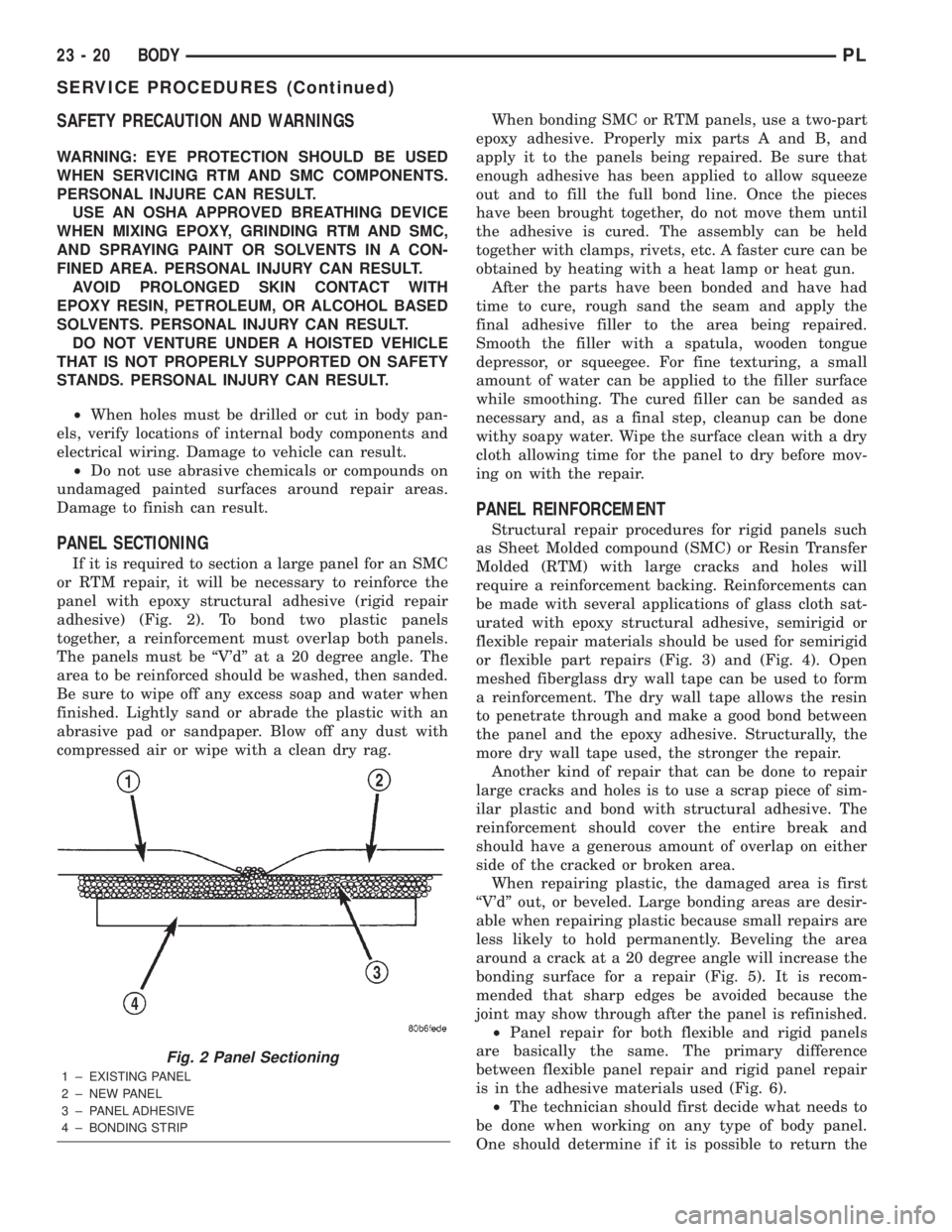
PANEL SECTIONING
If it is required to section a large panel for an SMC
or RTM repair, it will be necessary to reinforce the
panel with epoxy structural adhesive (rigid repair
adhesive) (Fig. 2). To bond two plastic panels
together, a reinforcement must overlap both panels.
The panels must be ªV'dº at a 20 degree angle. The
area to be reinforced should be washed, then sanded.
Be sure to wipe off any excess soap and water when
finished. Lightly sand or abrade the plastic with an
abrasive pad or sandpaper. Blow off any dust with
compressed air or wipe with a clean dry rag.When bonding SMC or RTM panels, use a two-part
epoxy adhesive. Properly mix parts A and B, and
apply it to the panels being repaired. Be sure that
enough adhesive has been applied to allow squeeze
out and to fill the full bond line. Once the pieces
have been brought together, do not move them until
the adhesive is cured. The assembly can be held
together with clamps, rivets, etc. A faster cure can be
obtained by heating with a heat lamp or heat gun.
After the parts have been bonded and have had
time to cure, rough sand the seam and apply the
final adhesive filler to the area being repaired.
Smooth the filler with a spatula, wooden tongue
depressor, or squeegee. For fine texturing, a small
amount of water can be applied to the filler surface
while smoothing. The cured filler can be sanded as
necessary and, as a final step, cleanup can be done
withy soapy water. Wipe the surface clean with a dry
cloth allowing time for the panel to dry before mov-
ing on with the repair.
PANEL REINFORCEMENT
Structural repair procedures for rigid panels such
as Sheet Molded compound (SMC) or Resin Transfer
Molded (RTM) with large cracks and holes will
require a reinforcement backing. Reinforcements can
be made with several applications of glass cloth sat-
urated with epoxy structural adhesive, semirigid or
flexible repair materials should be used for semirigid
or flexible part repairs (Fig. 3) and (Fig. 4). Open
meshed fiberglass dry wall tape can be used to form
a reinforcement. The dry wall tape allows the resin
to penetrate through and make a good bond between
the panel and the epoxy adhesive. Structurally, the
more dry wall tape used, the stronger the repair.
Another kind of repair that can be done to repair
large cracks and holes is to use a scrap piece of sim-
ilar plastic and bond with structural adhesive. The
reinforcement should cover the entire break and
should have a generous amount of overlap on either
side of the cracked or broken area.
When repairing plastic, the damaged area is first
ªV'dº out, or beveled. Large bonding areas are desir-
able when repairing plastic because small repairs are
less likely to hold permanently. Beveling the area
around a crack at a 20 degree angle will increase the
bonding surface for a repair (Fig. 5). It is recom-
mended that sharp edges be avoided because the
joint may show through after the panel is refinished.
²Panel repair for both flexible and rigid panels
are basically the same. The primary difference
between flexible panel repair and rigid panel repair
is in the adhesive materials used (Fig. 6).
²The technician should first decide what needs to
be done when working on any type of body panel.
One should determine if it is possible to return the
Fig. 2 Panel Sectioning
1 ± EXISTING PANEL
2 ± NEW PANEL
3 ± PANEL ADHESIVE
4 ± BONDING STRIP
23 - 20 BODYPL
SERVICE PROCEDURES (Continued)