2000 DODGE NEON warning light
[x] Cancel search: warning lightPage 344 of 1285
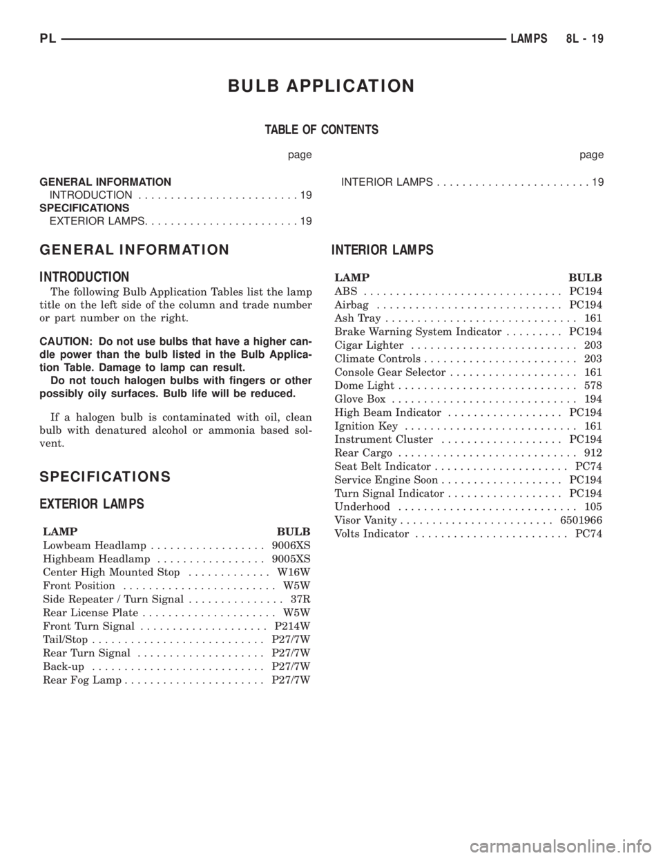
BULB APPLICATION
TABLE OF CONTENTS
page page
GENERAL INFORMATION
INTRODUCTION.........................19
SPECIFICATIONS
EXTERIOR LAMPS........................19INTERIOR LAMPS........................19
GENERAL INFORMATION
INTRODUCTION
The following Bulb Application Tables list the lamp
title on the left side of the column and trade number
or part number on the right.
CAUTION: Do not use bulbs that have a higher can-
dle power than the bulb listed in the Bulb Applica-
tion Table. Damage to lamp can result.
Do not touch halogen bulbs with fingers or other
possibly oily surfaces. Bulb life will be reduced.
If a halogen bulb is contaminated with oil, clean
bulb with denatured alcohol or ammonia based sol-
vent.
SPECIFICATIONS
EXTERIOR LAMPS
LAMP BULB
Lowbeam Headlamp..................9006XS
Highbeam Headlamp.................9005XS
Center High Mounted Stop.............W16W
Front Position........................ W5W
Side Repeater / Turn Signal............... 37R
Rear License Plate..................... W5W
Front Turn Signal....................P214W
Tail/Stop...........................P27/7W
Rear Turn Signal....................P27/7W
Back-up...........................P27/7W
Rear Fog Lamp......................P27/7W
INTERIOR LAMPS
LAMP BULB
ABS ...............................PC194
Airbag.............................PC194
AshTray .............................. 161
Brake Warning System Indicator.........PC194
Cigar Lighter.......................... 203
Climate Controls........................ 203
Console Gear Selector.................... 161
Dome Light............................ 578
Glove Box............................. 194
High Beam Indicator..................PC194
Ignition Key........................... 161
Instrument Cluster...................PC194
Rear Cargo............................ 912
Seat Belt Indicator.....................PC74
Service Engine Soon...................PC194
Turn Signal Indicator..................PC194
Underhood............................ 105
Visor Vanity........................6501966
Volts Indicator........................PC74
PLLAMPS 8L - 19
Page 348 of 1285
DIAGNOSIS AND TESTING
AIRBAG SYSTEM
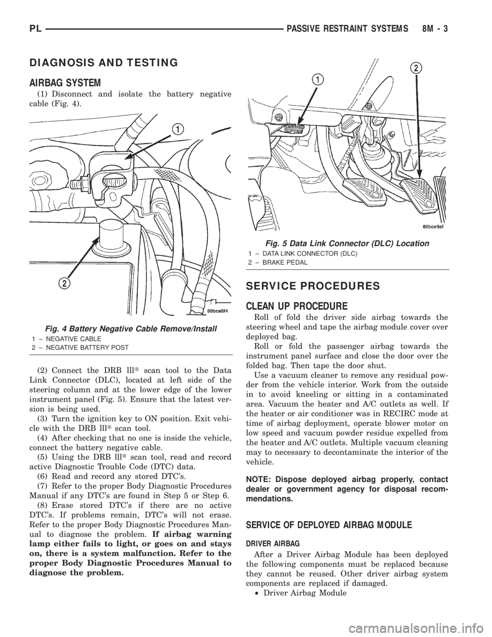
(1) Disconnect and isolate the battery negative
cable (Fig. 4).
(2) Connect the DRB llltscan tool to the Data
Link Connector (DLC), located at left side of the
steering column and at the lower edge of the lower
instrument panel (Fig. 5). Ensure that the latest ver-
sion is being used.
(3) Turn the ignition key to ON position. Exit vehi-
cle with the DRB llltscan tool.
(4) After checking that no one is inside the vehicle,
connect the battery negative cable.
(5) Using the DRB llltscan tool, read and record
active Diagnostic Trouble Code (DTC) data.
(6) Read and record any stored DTC's.
(7) Refer to the proper Body Diagnostic Procedures
Manual if any DTC's are found in Step 5 or Step 6.
(8) Erase stored DTC's if there are no active
DTC's. If problems remain, DTC's will not erase.
Refer to the proper Body Diagnostic Procedures Man-
ual to diagnose the problem.If airbag warning
lamp either fails to light, or goes on and stays
on, there is a system malfunction. Refer to the
proper Body Diagnostic Procedures Manual to
diagnose the problem.
SERVICE PROCEDURES
CLEAN UP PROCEDURE
Roll of fold the driver side airbag towards the
steering wheel and tape the airbag module cover over
deployed bag.
Roll or fold the passenger airbag towards the
instrument panel surface and close the door over the
folded bag. Then tape the door shut.
Use a vacuum cleaner to remove any residual pow-
der from the vehicle interior. Work from the outside
in to avoid kneeling or sitting in a contaminated
area. Vacuum the heater and A/C outlets as well. If
the heater or air conditioner was in RECIRC mode at
time of airbag deployment, operate blower motor on
low speed and vacuum powder residue expelled from
the heater and A/C outlets. Multiple vacuum cleaning
may to necessary to decontaminate the interior of the
vehicle.
NOTE: Dispose deployed airbag properly, contact
dealer or government agency for disposal recom-
mendations.
SERVICE OF DEPLOYED AIRBAG MODULE
DRIVER AIRBAG
After a Driver Airbag Module has been deployed
the following components must be replaced because
they cannot be reused. Other driver airbag system
components are replaced if damaged.
²Driver Airbag Module
Fig. 4 Battery Negative Cable Remove/Install
1 ± NEGATIVE CABLE
2 ± NEGATIVE BATTERY POST
Fig. 5 Data Link Connector (DLC) Location
1 ± DATA LINK CONNECTOR (DLC)
2 ± BRAKE PEDAL
PLPASSIVE RESTRAINT SYSTEMS 8M - 3
Page 349 of 1285
²Clockspring assembly
²Steering Column Assembly w/Lower Steering
Column Coupler
PASSENGER AIRBAG
After a Passenger Airbag Module has been
deployed, replace the following components because
they cannot be reused.
²Passenger Airbag Module
Inspect all the attaching hardware and instrument
panel for damage. If damage is evident, components
should be replaced.
HANDLING AIRBAG MODULES
DEPLOYED AIRBAG MODULE
The vehicle interior may contain a very small
amount of sodium hydroxide powder, a by-product of
airbag deployment. Sodium hydroxide powder can
irritate the skin, eyes, nose and throat. Wear safety
glasses, rubber gloves, and long sleeved clothing
when cleaning any of the powder residue from the
vehicle.
If you find that the cleanup is irritating your skin,
run cool water over the affected area. Also, if you
experience nasal or throat irritation, exit the vehicle
for fresh air until the irritation ceases. If irritation
continues, see a physician.
UNDEPLOYED AIRBAG MODULE
The airbag modules must be stored in its original
special container until used for service. At no time
should a source of electricity be permitted near the
inflator on the back of an airbag module. When car-
rying or handling an undeployed airbag module, the
trim side of the airbag should be pointing away from
the body to minimize possibility of injury if acciden-
tal deployment occurs. Do not place undeployed air-
bag face down on a solid surface, the airbag will
propel into the air if accidentally deployment occurs.
MAINTENANCE INSPECTION
(1) Check the airbag warning lamp for proper
operation as follows:
(a) Turn ignition switch to the ON position, the
airbag warning lamp should light. If not, test the
system using a DRB llltscan tool and the proper
Body Diagnostic Procedures Manual.
(b) The airbag warning lamp lights, but fails to
go out after eight seconds. Test the system using a
DRB llltscan tool and the proper Body Diagnostic
Procedures Manual.
(c) After correcting active malfunction erase
stored Diagnostic Trouble Codes (DTC's).
REMOVAL AND INSTALLATION
AIRBAG CONTROL MODULE (ACM)
WARNING: THE ACM CONTAINS THE SENSING
ELEMENT AND A SAFING SENSOR WHICH
ENABLES THE SYSTEM TO DEPLOY THE AIR-
BAGS. TO AVOID ACCIDENTAL DEPLOYMENT,
NEVER CONNECT ACM ELECTRICALLY TO THE
SYSTEM WHILE VEHICLE BATTERY IS CON-
NECTED.
DISCONNECT AND ISOLATE THE BATTERY NEG-
ATIVE (GROUND) CABLE BEFORE BEGINNING ANY
AIRBAG SYSTEM COMPONENT REMOVAL OR
INSTALLATION PROCEDURE. THIS WILL DISABLE
THE AIRBAG SYSTEM. FAILURE TO DISCONNECT
BATTERY COULD RESULT IN ACCIDENTAL AIRBAG
DEPLOYMENT AND POSSIBLE PERSONAL INJURY.
ALLOW SYSTEM CAPACITOR TO DISCHARGE
FOR 1 MINUTE BEFORE REMOVING ANY AIRBAG
COMPONENTS.
REMOVAL
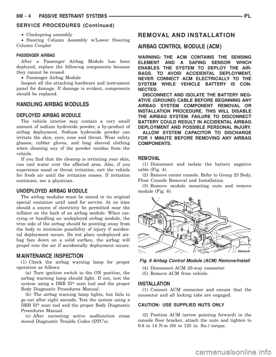
(1) Disconnect and isolate the battery negative
cable (Fig. 4).
(2) Remove center console. Refer to Group 23 Body,
Floor Console Removal and Installation.
(3) Remove module mounting nuts and remove
module (Fig. 6).
(4) Disconnect ACM 23-way connector.
(5) Remove ACM from vehicle.
INSTALLATION
(1) Connect ACM connector and ensure that the
connector and all locking tabs are engaged.
CAUTION: USE SUPPLIED NUTS ONLY
(2) Position ACM (arrow pointing forward) in the
console floor bracket, attach the nuts and tighten to
9.6 to 14 N´m (85 to 125 in. lbs.) torque.
Fig. 6 Airbag Control Module (ACM) Remove/Install
8M - 4 PASSIVE RESTRAINT SYSTEMSPL
SERVICE PROCEDURES (Continued)
Page 350 of 1285
(3) Install center console assembly. Refer to Group
23 Body, Floor Console Removal and Installation.
(4) Do not connect battery negative cable. Refer to
Diagnosis and Testing for Airbag System Test for the
proper procedures.
CLOCKSPRING
WARNING: DISCONNECT AND ISOLATE THE BAT-
TERY NEGATIVE (GROUND) CABLE BEFORE
BEGINNING ANY AIRBAG SYSTEM COMPONENT
REMOVAL OR INSTALLATION PROCEDURE. THIS
WILL DISABLE THE AIRBAG SYSTEM. FAILURE TO
DISCONNECT BATTERY COULD RESULT IN ACCI-
DENTAL AIRBAG DEPLOYMENT AND POSSIBLE
PERSONAL INJURY.
ALLOW SYSTEM CAPACITOR TO DISCHARGE
FOR 1 MINUTE BEFORE REMOVING ANY AIRBAG
COMPONENTS.
REMOVAL
(1) Place the front road wheels in the straight
ahead position then:
²Rotate the steering wheel half turn (180
degrees) to the right (clockwise).
²Lock column with ignition lock cylinder.
(2) Disconnect and isolate the battery negative
cable (Fig. 4).
(3) Wait one minute for the reserve capacitor to
discharge before removing non-deployed module.
(4) Remove steering wheel. Refer to Steering
Wheel Removal and Installation in this section.
(5) Remove upper and lower steering column
shrouds to gain access to clockspring wiring. Refer to
Group 8E Instrument Panel Systems, Steering Col-
umn Shroud Removal and Installation.
(6) Remove multi-function switch. Refer to Group
8J-Turn Signal and Hazard Warning Systems, Multi-
Function Switch Removal and Installation.
(7) Disconnect the 7-way connector between the
clockspring and the instrument panel wiring harness
at the base of the clockspring.
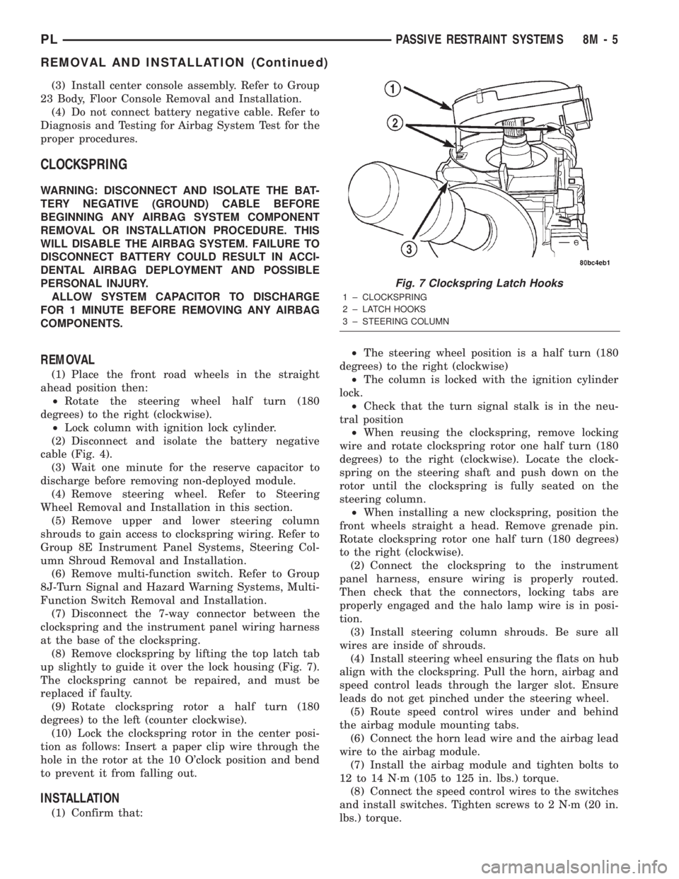
(8) Remove clockspring by lifting the top latch tab
up slightly to guide it over the lock housing (Fig. 7).
The clockspring cannot be repaired, and must be
replaced if faulty.
(9) Rotate clockspring rotor a half turn (180
degrees) to the left (counter clockwise).
(10) Lock the clockspring rotor in the center posi-
tion as follows: Insert a paper clip wire through the
hole in the rotor at the 10 O'clock position and bend
to prevent it from falling out.
INSTALLATION
(1) Confirm that:²The steering wheel position is a half turn (180
degrees) to the right (clockwise)
²The column is locked with the ignition cylinder
lock.
²Check that the turn signal stalk is in the neu-
tral position
²When reusing the clockspring, remove locking
wire and rotate clockspring rotor one half turn (180
degrees) to the right (clockwise). Locate the clock-
spring on the steering shaft and push down on the
rotor until the clockspring is fully seated on the
steering column.
²When installing a new clockspring, position the
front wheels straight a head. Remove grenade pin.
Rotate clockspring rotor one half turn (180 degrees)
to the right (clockwise).
(2) Connect the clockspring to the instrument
panel harness, ensure wiring is properly routed.
Then check that the connectors, locking tabs are
properly engaged and the halo lamp wire is in posi-
tion.
(3) Install steering column shrouds. Be sure all
wires are inside of shrouds.
(4) Install steering wheel ensuring the flats on hub
align with the clockspring. Pull the horn, airbag and
speed control leads through the larger slot. Ensure
leads do not get pinched under the steering wheel.
(5) Route speed control wires under and behind
the airbag module mounting tabs.
(6) Connect the horn lead wire and the airbag lead
wire to the airbag module.
(7) Install the airbag module and tighten bolts to
12 to 14 N´m (105 to 125 in. lbs.) torque.
(8) Connect the speed control wires to the switches
and install switches. Tighten screws to 2 N´m (20 in.
lbs.) torque.
Fig. 7 Clockspring Latch Hooks
1 ± CLOCKSPRING
2 ± LATCH HOOKS
3 ± STEERING COLUMN
PLPASSIVE RESTRAINT SYSTEMS 8M - 5
REMOVAL AND INSTALLATION (Continued)
Page 358 of 1285
(2) Connect an ammeter in series with the battery.
Push the rear window defogger switch to the ON
position (Fig. 2). A distinct increase in amperage
draw should be noted.
(3) The rear window defogger operation can be
checked by feeling the glass. A distinct difference in
temperature between the grid lines and adjacent
clear glass can be detected in three to four minutes
of operation.
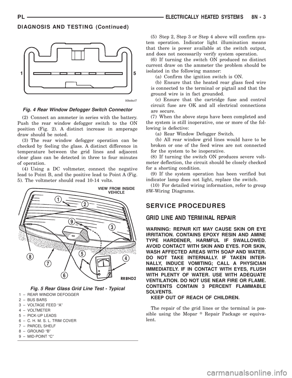
(4) Using a DC voltmeter, connect the negative
lead to Point B, and the positive lead to Point A (Fig.
5). The voltmeter should read 10-14 volts.(5) Step 2, Step 3 or Step 4 above will confirm sys-
tem operation. Indicator light illumination means
that there is power available at the switch output,
and does not necessarily verify system operation.
(6) If turning the switch ON produced no distinct
current draw on the ammeter the problem should be
isolated in the following manner:
(a) Confirm the ignition switch is ON.
(b) Ensure that the heated rear glass feed wire
is connected to the terminal or pigtail and that the
ground wire is in fact grounded.
(c) Ensure that the cartridge fuse and control
circuit fuse are OK and all electrical connections
are secure.
(7) When the above steps have been completed and
the system is still inoperative, one or more of the fol-
lowing is defective:
(a) Rear Window Defogger Switch.
(b) All rear window grid lines would have to be
broken or one of the feed wires are not connected
for the system to be inoperative.
(8) If turning the switch ON produces severe volt-
meter deflection, the circuit should be closely checked
for a shorting condition.
(9) If the system operation has been verified but
indicator lamp does not light, replace the switch.
(10) For detailed wiring information, refer to group
8W-Wiring Diagrams.
SERVICE PROCEDURES
GRID LINE AND TERMINAL REPAIR
WARNING: REPAIR KIT MAY CAUSE SKIN OR EYE
IRRITATION. CONTAINS EPOXY RESIN AND AMINE
TYPE HARDENER, HARMFUL IF SWALLOWED.
AVOID CONTACT WITH SKIN AND EYES. FOR SKIN,
WASH AFFECTED AREAS WITH SOAP AND WATER.
DO NOT TAKE INTERNALLY. IF TAKEN INTER-
NALLY, INDUCE VOMITING; CALL A PHYSICIAN
IMMEDIATELY. IF IN CONTACT WITH EYES, FLUSH
WITH PLENTY OF WATER. USE WITH ADEQUATE
VENTILATION. DO NOT USE NEAR FIRE OR FLAME.
CONTENTS CONTAIN 3 PERCENT FLAMMABLE
SOLVENTS.
KEEP OUT OF REACH OF CHILDREN.
The repair of the grid lines or the terminal is pos-
sible using the MopartRepair Package or equiva-
lent.
Fig. 4 Rear Window Defogger Switch Connector
Fig. 5 Rear Glass Grid Line Test - Typical
1 ± REAR WINDOW DEFOGGER
2 ± BUS BARS
3 ± VOLTAGE FEED ªAº
4 ± VOLTMETER
5 ± PICK-UP LEADS
6 ± C. H. M. S. L. TRIM COVER
7 ± PARCEL SHELF
8 ± GROUND ªBº
9 ± MID-POINT ªCº
PLELECTRICALLY HEATED SYSTEMS 8N - 3
DIAGNOSIS AND TESTING (Continued)
Page 375 of 1285
memory to determine whether a valid key is in the
ignition lock cylinder.
The Sentry Key transponder cannot be repaired
and, if faulty or damaged, it must be replaced.
SENTRY KEY IMMOBILIZER SYSTEM
INDICATOR LAMP
The Sentry Key Immobilizer System (SKIS) uses
the Vehicle Theft Security System (VTSS) indicator
LED to give an indication when the SKIS is faulty or
when the vehicle has been immobilized due to the
use of an invalid ignition key. The LED is controlled
by the instrument cluster circuitry based upon mes-
sages received from the Sentry Key Immobilizer
Module (SKIM) through the Body Control Module
(BCM) on the Programmable Communication Inter-
face (PCI) bus.
The SKIM sends messages to the instrument clus-
ter, via the BCM, to turn the LED on for about three
seconds when the ignition switch is turned to the ON
position as a bulb test. After completion of the bulb
test, the SKIM sends PCI bus messages to keep the
LED off for a duration of about one second. Then the
SKIM sends messages to the instrument cluster cir-
cuitry to turn the LED on or off based upon the
results of the SKIS self-tests. If the VTSS indicator
LED comes on and stays on after the bulb test, it
indicates that the SKIM has detected a system mal-
function and/or that the SKIS has become inopera-
tive. If the SKIM detects an invalid key when the
ignition switch is turned to the ON position, it sends
messages to the instrument cluster to flash the VTSS
indicator LED.
The SKIM can also send messages to the instru-
ment cluster to flash the LED and to generate a sin-
gle audible chime tone. These functions serve as an
indication to the customer that the SKIS has been
placed in its ªCustomer Learnº programming mode.
See Sentry Key Immobilizer System Transponder
Programming in this group for more information on
the ªCustomer Learnº programming mode.
The VTSS indicator LED uses a replaceable Light
Emitting Diode (LED) on the instrument cluster elec-
tronic circuit board. Refer to Group 8E - Instrument
Panel Systems for Cluster Lamp Removal and Instal-
lation. If the VTSS indicator LED comes on and
stays on after the bulb test function, diagnosis of the
SKIS should be performed with a DRB IIItscan tool
and the proper Body Diagnostic Procedures Manual.
TRIGGERING THE VTSS
After the VTSS is armed, any of the following will
trigger the system:
²Opening any door.
²Opening the hood.
²Removing the trunk lock cylinder.²Turning the ignition to the RUN/START position
with an invalid Sentry Key.
NOTE: The ignition switch can be turned to the
accessory position without triggering the alarm sys-
tem.
DIAGNOSIS AND TESTING
SENTRY KEY IMMOBILIZER SYSTEM
WARNING: ON VEHICLES EQUIPPED WITH AIR-
BAGS, REFER TO GROUP 8M - PASSIVE
RESTRAINT SYSTEMS BEFORE ATTEMPTING ANY
STEERING WHEEL, STEERING COLUMN, OR
INSTRUMENT PANEL COMPONENT DIAGNOSIS OR
SERVICE. FAILURE TO TAKE THE PROPER PRE-
CAUTIONS COULD RESULT IN ACCIDENTAL AIR-
BAG DEPLOYMENT AND POSSIBLE PERSONAL
INJURY.
NOTE: The following tests may not prove conclu-
sive in the diagnosis of this system. The most reli-
able, efficient, and accurate means to diagnose the
Sentry Key Immobilizer System (SKIS) involves the
use of a DRB lllTscan tool and the proper Body
Diagnostic Procedures Manual.
The Sentry Key Immobilizer System (SKIS) and
the Programmable Communication Interface (PCI)
bus network should be diagnosed using a DRB lllt
scan tool. The DRB IIItwill allow confirmation that
the PCI bus is functional, that the Sentry Key Immo-
bilizer Module (SKIM) is placing the proper messages
on the PCI bus, and that the Powertrain Control
Module (PCM) and the instrument cluster are receiv-
ing the PCI bus messages. Refer to the proper Body
Diagnostic Procedures Manual. Refer to Group
8W-Wiring Diagrams for complete circuit descriptions
and diagrams.
(1) Check the fuses in the fuse block. If OK, go to
Step 2. If not OK, repair the shorted circuit or com-
ponent as required and replace the faulty fuse.
(2) Disconnect and isolate the battery negative
cable (Fig. 3). Unplug the wire harness connector at
the SKIM. Check for continuity between the ground
circuit cavity of the SKIM wire harness connector
and a good ground. There should be continuity. If
OK, go to Step 3. If not OK, repair the open circuit to
ground as required.
(3) Connect the battery negative cable. Check for
battery voltage at the fused B(+) circuit cavity of the
SKIM wire harness connector. If OK, go to Step 4. If
not OK, repair the open circuit to the fuse in the fuse
block as required.
8Q - 4 VEHICLE THEFT/SECURITY SYSTEMPL
DESCRIPTION AND OPERATION (Continued)
Page 390 of 1285
CHIME WARNING/REMINDER SYSTEM
TABLE OF CONTENTS
page page
DESCRIPTION AND OPERATION
INTRODUCTION..........................1
DIAGNOSIS AND TESTING
FASTEN SEAT BELTS......................1
HEADLAMPS LEFT ON.....................1
KEY LEFT IN IGNITION SWITCH.............1CHIME SYSTEM CONDITIONS...............1
REMOVAL AND INSTALLATION
CHIME..................................2
SEAT BELT BUCKLE.......................2
HEADLAMP SWITCH......................2
KEY-IN SWITCH..........................2
DESCRIPTION AND OPERATION
INTRODUCTION
WARNING: ON VEHICLES EQUIPPED WITH AN AIR-
BAG, REFER TO THE AIRBAG PORTION OF THIS
SECTION FOR STEERING WHEEL OR SWITCH
REMOVAL AND INSTALLATION PROCEDURES.
The seat belt reminder system uses both visual
and audible signals. A combined seat belt and key
reminder chime with a red light on the instrument
panel.
The system will always illuminate the seat belt
reminder lamp for four to eight seconds when the
ignition switch is turned to the ON position. The
CHIME will sound during the same time interval if
the driver's seat belt is not fastened. Passenger belts
are not connected to the system.
The chime will activate if the drivers door is
opened and:
²The key is in the ignition switch, with the igni-
tion switch in either the OFF or accessory (ACC)
position.
²The head lamps are ON.
The chime is integral to the instrument cluster.
DIAGNOSIS AND TESTING
FASTEN SEAT BELTS
To test the fasten seat belts function, turn the igni-
tion switch to the ON position with the driver's seat
belt unbuckled and fully retracted. The seat belt
warning lamp should light for four to eight seconds
and the tone should sound three to five times.
If the lamp does not light, check the connection at
the seat belt retractor and the LED in the instru-
ment cluster. Replace as necessary.
HEADLAMPS LEFT ON
These are the conditions that have to be met for
the headlamps on, chime function to work:
²Headlamps ON.
²Driver's door open.
²Key removed from the ignition switch.
Chime should sound until headlamps are turned
off or driver's door is closed.
If these conditions are met and there is still a
problem with the system, replace the instrument
cluster. Refer to Group 8E-Instrument Panel and
Systems, Instrument Cluster Removal and Installa-
tion.
KEY LEFT IN IGNITION SWITCH
To test the key left in ignition function, insert key
into the ignition and open the driver's door. Chime
should sound until key is removed from ignition or
driver's door is closed.
If these conditions are met and there is still a
problem with the system, replace the instrument
cluster. Refer to Group 8E-Instrument Panel and
Systems, Instrument Cluster Removal and Installa-
tion.
CHIME SYSTEM CONDITIONS
NO TONE WHEN IGNITION SWITCH IS TURNED ON
AND DRIVERS SEAT BELT IS UNBUCKLED
(1) Using an ohmmeter, with the seat belt fully
retracted, check for continuity to ground at Pin 25 of
the cluster harness connector. If OK, go to step 2. If
not OK, repair as necessary.
(2) Using voltmeter, check for battery feed at Pin
21 of the cluster harness connector. Check for igni-
tion feed at Pin 15 of the cluster harness connector.
If not OK, repair as necessary.
PLCHIME WARNING/REMINDER SYSTEM 8U - 1
Page 410 of 1285
8W-02 COMPONENT INDEX
Component Page
A/C Compressor Clutch Relay............8W-42
A/C Compressor Clutch.................8W-42
A/C Cycling Switch....................8W-42
A/C Heater Blower Motor...............8W-42
A/C Heater Control....................8W-42
A/C Pressure Switches..................8W-42
Airbag Control Module.................8W-43
Airbags.............................8W-43
Antenna.............................8W-47
Automatic Shut Down Relay.............8W-30
Back-Up Lamp Switch..................8W-51
Back-Up Lamps.......................8W-51
Battery.............................8W-20
Blower Motor Resistor Block.............8W-42
Brake Lamp Switch....................8W-30
Brake Shift Interlock Solenoid...........8W-30
Brake Warning Indicator Switch..........8W-40
Camshaft Position Sensor...............8W-30
Cargo Lamp..........................8W-44
Center High Mounted Stop Lamp.........8W-51
Center Stack Lamp....................8W-44
Cigar Lighter/Power Outlet..............8W-41
Circuit Breakers (FB)..................8W-11
City Lamps..........................8W-50
Clockspring.....................8W-33, 41, 43
Clutch Interlock Switch.................8W-30
Combination Flasher...................8W-52
Controller Anti-Lock Brake..............8W-35
Crankshaft Position Sensor..............8W-30
Data Link Connector...................8W-30
Decklid Release Switch.................8W-44
Decklid Solenoid......................8W-61
Diode No. 1..........................8W-42
Dome Lamp..........................8W-44
Dome Lamp/Intrusion Sensor............8W-44
Door Ajar Switches....................8W-40
Door Lock Motors.....................8W-61
Engine Coolant Temperature Sensor.......8W-30
Engine Oil Pressure Switch..............8W-30
Engine Starter Motor Relay.............8W-21
Engine Starter Motor..................8W-21
Fog Lamps........................8W-50, 51
Front Fog Lamp Switch.................8W-50
Fuel Injectors........................8W-30
Fuel Pump Module....................8W-30
Fuel Pump Relay......................8W-30
Fuel Tank...........................8W-30
Fuses (FB)...........................8W-11
Fuses (PDC).........................8W-10
Fuse Block...........................8W-11
Fusible Link A11...................8W-20, 21
Grounds.............................8W-15Component Page
Generator...........................8W-20
Glove Box Lamp/Switch.................8W-44
Headlamp Beam Select..............8W-40, 50
Headlamp Leveling Motors..............8W-50
Headlamp Leveling Switch Illumination....8W-50
Headlamp Leveling Switch..............8W-50
Headlamp Switch...................8W-50, 51
Headlamps..........................8W-50
Horns..............................8W-41
Horn Relay..........................8W-41
Horn Switch.........................8W-41
Hood Ajar Switch......................8W-39
Idle Air Control Motor..................8W-30
Ignition Coil.........................8W-30
Ignition Switch.......................8W-10
Indicators...........................8W-40
Indicator Drivers......................8W-40
Inlet Air Temperature Sensor............8W-30
Instrument Cluster....................8W-40
Instrument Panel Drivers...............8W-40
Knock Sensor.........................8W-30
Leak Detection Pump..................8W-30
License Lamps........................8W-51
Manifold Absolute Pressure Sensor........8W-30
Map/Reading Lamps...................8W-44
Multi- Function Switch.........8W-40, 50, 51, 52
Noise Suppressor......................8W-30
Oxygen Sensors.......................8W-30
Park Brake Switch....................8W-40
Park/Neutral Position Switch............8W-51
Park/Turn Signal Lamps................8W-52
Power Distribution Center...............8W-10
Power Mirror Switch...................8W-62
Power Steering Pressure Switch..........8W-30
Powertrain Control Module..............8W-30
PRNDL Lamp........................8W-44
Proportional Evap/Purge Solenoid.........8W-30
Radiator Fan Motor....................8W-42
Radiator Fan Relay....................8W-42
Radio...............................8W-47
Rear Window Defogger Switch...........8W-48
Rear Window Defogger.................8W-48
Remote Keyless Entry Module............8W-39
Repeater Lamps......................8W-52
Seat Belt Switch......................8W-40
Sentry Key Immobilizer Module..........8W-39
Side Marker Lamps....................8W-50
Siren...............................8W-39
Speakers............................8W-47
Splice Information.....................8W-70
Sunroof Control Module................8W-64
Sunroof Motor........................8W-64
PL8W - 02 COMPONENT INDEX 8W - 02 - 1