2000 DODGE NEON vacuum
[x] Cancel search: vacuumPage 189 of 1285
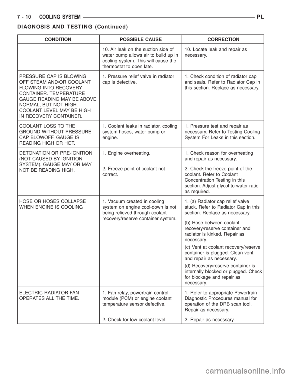
CONDITION POSSIBLE CAUSE CORRECTION
10. Air leak on the suction side of
water pump allows air to build up in
cooling system. This will cause the
thermostat to open late.10. Locate leak and repair as
necessary.
PRESSURE CAP IS BLOWING
OFF STEAM AND/OR COOLANT
FLOWING INTO RECOVERY
CONTAINER. TEMPERATURE
GAUGE READING MAY BE ABOVE
NORMAL, BUT NOT HIGH.
COOLANT LEVEL MAY BE HIGH
IN RECOVERY CONTAINER.1. Pressure relief valve in radiator
cap is defective.1. Check condition of radiator cap
and seals. Refer to Radiator Cap in
this section. Replace as necessary.
COOLANT LOSS TO THE
GROUND WITHOUT PRESSURE
CAP BLOWOFF. GAUGE IS
READING HIGH OR HOT.1. Coolant leaks in radiator, cooling
system hoses, water pump or
engine.1. Pressure test and repair as
necessary. Refer to Testing Cooling
System For Leaks in this section.
DETONATION OR PRE-IGNITION
(NOT CAUSED BY IGNITION
SYSTEM). GAUGE MAY OR MAY
NOT BE READING HIGH.1. Engine overheating. 1. Check reason for overheating
and repair as necessary.
2. Freeze point of coolant not
correct.2. Check the freeze point of the
coolant. Refer to Coolant
Concentration Testing in this
section. Adjust glycol-to-water ratio
as required.
HOSE OR HOSES COLLAPSE
WHEN ENGINE IS COOLING1. Vacuum created in cooling
system on engine cool-down is not
being relieved through coolant
recovery/reserve container system.1. (a) Radiator cap relief valve
stuck. Refer to Radiator Cap in this
section. Replace as necessary.
(b) Hose between coolant
recovery/reserve container and
radiator is kinked. Repair as
necessary.
(c) Vent at coolant recovery/reserve
container is plugged. Clean vent
and repair as necessary.
(d) Recovery/reserve container is
internally blocked or plugged. Check
for blockage and repair as
necessary.
ELECTRIC RADIATOR FAN
OPERATES ALL THE TIME.1. Fan relay, powertrain control
module (PCM) or engine coolant
temperature sensor defective.1. Refer to appropriate Powertrain
Diagnostic Procedures manual for
operation of the DRB scan tool.
Repair as necessary.
2. Check for low coolant level. 2. Repair as necessary.
7 - 10 COOLING SYSTEMPL
DIAGNOSIS AND TESTING (Continued)
Page 195 of 1285
the coolant to expand. Reattach the tester. If the nee-
dle on the dial fluctuates it indicates a combustion
leak, usually a head gasket leak.
WARNING: WITH THE PRESSURE TESTER IN
PLACE PRESSURE BUILDS UP QUICKLY. ANY
EXCESSIVE PRESSURE BUILD-UP DUE TO CON-
TINUOUS ENGINE OPERATION MUST BE
RELEASED TO A SAFE PRESSURE POINT. NEVER
PERMIT PRESSURE TO EXCEED 138 kPa (20 psi).
If the needle on the dial does not fluctuate, race
the engine a few times. If an abnormal amount of
coolant or steam is emitted from the tail pipe, it may
indicate a faulty head gasket, cracked engine block,
or cracked cylinder head.
There may be internal leaks, which can be deter-
mined by removing the oil dipstick. If water globules
appear intermixed with the oil, it indicates an inter-
nal leak in the engine. If there is an internal leak,
the engine must be disassembled for repair.
PRESSURE CAP TO FILLER NECK SEAL
PRESSURE RELIEF CHECK
The pressure cap upper gasket (seal) pressure
relief can be checked by removing the overflow hose
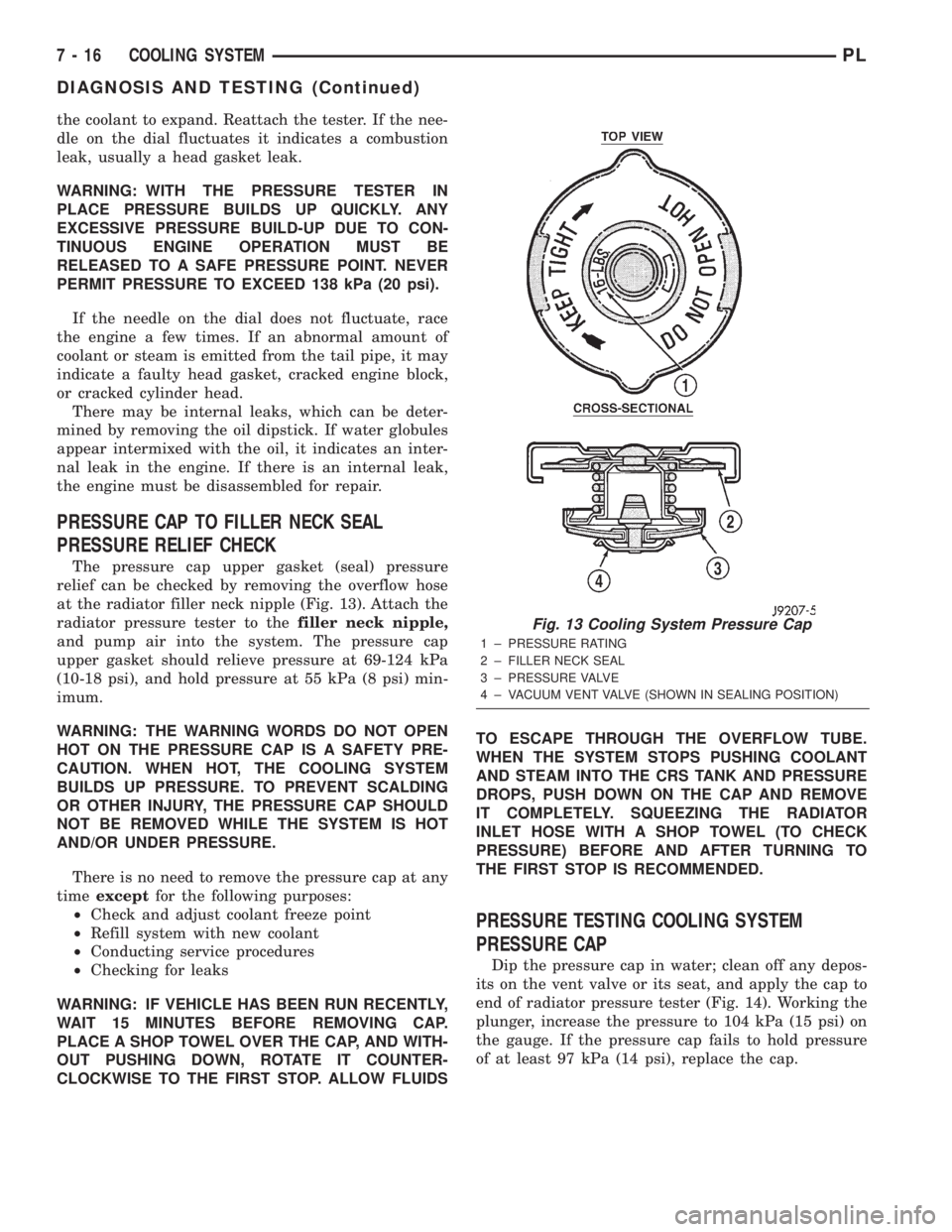
at the radiator filler neck nipple (Fig. 13). Attach the
radiator pressure tester to thefiller neck nipple,
and pump air into the system. The pressure cap
upper gasket should relieve pressure at 69-124 kPa
(10-18 psi), and hold pressure at 55 kPa (8 psi) min-
imum.
WARNING: THE WARNING WORDS DO NOT OPEN
HOT ON THE PRESSURE CAP IS A SAFETY PRE-
CAUTION. WHEN HOT, THE COOLING SYSTEM
BUILDS UP PRESSURE. TO PREVENT SCALDING
OR OTHER INJURY, THE PRESSURE CAP SHOULD
NOT BE REMOVED WHILE THE SYSTEM IS HOT
AND/OR UNDER PRESSURE.
There is no need to remove the pressure cap at any
timeexceptfor the following purposes:
²Check and adjust coolant freeze point
²Refill system with new coolant
²Conducting service procedures
²Checking for leaks
WARNING: IF VEHICLE HAS BEEN RUN RECENTLY,
WAIT 15 MINUTES BEFORE REMOVING CAP.
PLACE A SHOP TOWEL OVER THE CAP, AND WITH-
OUT PUSHING DOWN, ROTATE IT COUNTER-
CLOCKWISE TO THE FIRST STOP. ALLOW FLUIDSTO ESCAPE THROUGH THE OVERFLOW TUBE.
WHEN THE SYSTEM STOPS PUSHING COOLANT
AND STEAM INTO THE CRS TANK AND PRESSURE
DROPS, PUSH DOWN ON THE CAP AND REMOVE
IT COMPLETELY. SQUEEZING THE RADIATOR
INLET HOSE WITH A SHOP TOWEL (TO CHECK
PRESSURE) BEFORE AND AFTER TURNING TO
THE FIRST STOP IS RECOMMENDED.
PRESSURE TESTING COOLING SYSTEM
PRESSURE CAP
Dip the pressure cap in water; clean off any depos-
its on the vent valve or its seat, and apply the cap to
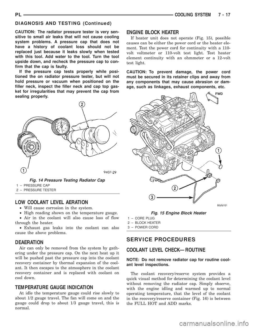
end of radiator pressure tester (Fig. 14). Working the
plunger, increase the pressure to 104 kPa (15 psi) on
the gauge. If the pressure cap fails to hold pressure
of at least 97 kPa (14 psi), replace the cap.
Fig. 13 Cooling System Pressure Cap
1 ± PRESSURE RATING
2 ± FILLER NECK SEAL
3 ± PRESSURE VALVE
4 ± VACUUM VENT VALVE (SHOWN IN SEALING POSITION)
7 - 16 COOLING SYSTEMPL
DIAGNOSIS AND TESTING (Continued)
Page 196 of 1285
CAUTION: The radiator pressure tester is very sen-
sitive to small air leaks that will not cause cooling
system problems. A pressure cap that does not
have a history of coolant loss should not be
replaced just because it leaks slowly when tested
with this tool. Add water to the tool. Turn the tool
upside down, and recheck the pressure cap to con-
firm that the cap is faulty.
If the pressure cap tests properly while posi-
tioned the on radiator pressure tester, but will not
hold pressure or vacuum when positioned on the
filler neck, inspect the filler neck and cap top gas-
ket for irregularities that may prevent the cap from
sealing properly.
LOW COOLANT LEVEL AERATION
²Will cause corrosion in the system.
²High reading shown on the temperature gauge.
²Air in the coolant will also cause loss of flow
through the heater.
²Exhaust gas leaks into the coolant can also
cause the above problems.
DEAERATION
Air can only be removed from the system by gath-
ering under the pressure cap. On the next heat up it
will be pushed past the pressure cap into the coolant
recovery container by thermal expansion of the cool-
ant. It then escapes to the atmosphere in the coolant
recovery container and is replaced with coolant on
cool down.
TEMPERATURE GAUGE INDICATION
At idle the temperature gauge could rise slowly to
about 1/2 gauge travel. The fan will come on and the
gauge could drop to about 1/3 gauge travel, this is
normal.
ENGINE BLOCK HEATER
If heater unit does not operate (Fig. 15), possible
causes can be either the power cord or the heater ele-
ment. Test the power cord for continuity with a 110-
volt voltmeter or 110-volt test light. Test heater
element continuity with an ohmmeter or a 12-volt
test light.
CAUTION: To prevent damage, the power cord
must be secured in its retainer clips and away from
any components that may cause abrasion or dam-
age, such as linkages, exhaust components, etc.
SERVICE PROCEDURES
COOLANT LEVEL CHECKÐROUTINE
NOTE: Do not remove radiator cap for routine cool-
ant level inspections.
The coolant recovery/reserve system provides a
quick visual method for determining the coolant level
without removing the radiator cap. Simply observe,
with the engine idling and warmed up to normal
operating temperature, that the level of the coolant
in the recovery/reserve container (Fig. 16) is between
the FULL HOT and ADD marks.
Fig. 14 Pressure Testing Radiator Cap
1 ± PRESSURE CAP
2 ± PRESSURE TESTER
Fig. 15 Engine Block Heater
1 ± CORE PLUG
2 ± BLOCK HEATER
3 ± POWER CORD
PLCOOLING SYSTEM 7 - 17
DIAGNOSIS AND TESTING (Continued)
Page 208 of 1285
(3) Remove engine thermostat and reinstall ther-
mostat housing. A gasket may be needed to seal thehousing to cylinder head because the seal is part of
thermostat.
(4) Install suitable flushing gun to thermostat
housing hose. Turn on water, and when engine is
filled, turn on air, but no higher than 138 kPa (20
psi) in short blasts. Allow engine to fill between
blasts of air. Continue this procedure until water
runs clean.
(5) Install thermostat and fill cooling system.
Refer to Cooling System Refilling in this section for
procedure.
REVERSE FLUSHING
Reverse flushing of the cooling system is the forc-
ing of water through the cooling system, using air
pressure in a direction opposite to that of the normal
flow of water. This is only necessary with dirty sys-
tems and evidence of partial plugging.
CHEMICAL CLEANING
One type of corrosion encountered with aluminum
cylinder heads is aluminum hydroxide deposits. Cor-
rosion products are carried to the radiator and depos-
ited when cooled off. They appear as dark grey when
wet and white when dry. This corrosion can be
removed with a two part cleaner (oxalic acid and
neutralizer) available in auto parts outlets. Follow
manufacturers directions for use.
ADJUSTMENTS
BELT TENSION
For belt tension adjustment procedure, refer to
Accessory Drive Belt Removal and Installation proce-
dure.
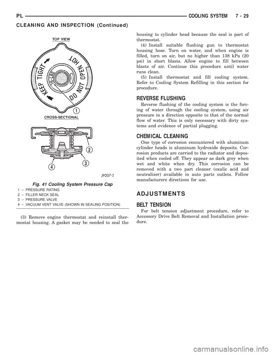
Fig. 41 Cooling System Pressure Cap
1 ± PRESSURE RATING
2 ± FILLER NECK SEAL
3 ± PRESSURE VALVE
4 ± VACUUM VENT VALVE (SHOWN IN SEALING POSITION)
PLCOOLING SYSTEM 7 - 29
CLEANING AND INSPECTION (Continued)
Page 249 of 1285
DESCRIPTION AND OPERATION
HEADLAMP SWITCH
The headlamp switch is part of the Multi-Function
Switch. Refer to Group 8J, Turn Signal and Flasher
for the Multi-Function Switch Test, Removal and
Installation procedures.
INSTRUMENT CLUSTER
There are two conventional instrument cluster
assemblies available. The clusters electronically drive
the speedometer, odometer, gauges, and tachometer
(if equipped). Refer to (Fig. 2) and (Fig. 3).
The instrument cluster controls the courtesy
lamps, it receives and sends messages to other mod-
ules via the PCI bus circuit, it controls all the instru-
ment illumination and the chime is also an integral
part of the cluster. The front turn signals are wired
through the cluster and then go to the front lamps.
The reason being that the DRL module is built into
the cluster (if equipped).
All gauges in the electronic clusters are the analog
type gauges. When the ignition switch is moved to
the OFF position, the cluster drives each gauge to its
lowest position. The individual gauges are not servi-
cable and require complete replacement of the cluster
if one or more gauges are inoperable.
One button is used to switch the display from trip
to total mileage. Holding the button when the display
is in the trip mode will reset the trip mileage. This
button is also used to put the cluster in self-diagnos-
tic mode. Refer to Service Procedures, Cluster Self-
Diagnostics in this section. Most of the indicators will
come on briefly for a bulb heck when the ignition is
turned from OFF to ON. All of the LED's are replace-
able.
In the event that the instrument cluster looses
communication with all other modules on the PCI
bus, the cluster will display ªnobusº in the VF dis-
play. The VF display also displays ªDoorº, ªCruiseº,
ªTracº, and odometer trip or total.
If the cluster does not detect voltage on the cour-
tesy lamp circuit, the message ªFUSEº will alternate
with the odometer/trip odometer for 30 seconds after
the ignition is turned on and for 15 seconds after the
vehicle is first moved. The lack of voltage can be due
to the M1 Fused B(+) (IOD) fuse being open, a bad or
missing courtesy lamp bulb, or a circuit problem.
WARNING AND INDICATOR LAMPS
The instrument cluster has warning lamps and
indicators for the following systems:
²Airbag
²Anti-lock Brakes (ABS) if equipped
²Brake warning
²Charging System²Front fog lamps (if equipped)
²High beam indicator
²Low fuel (premium cluster only)
²Low oil pressure
²Malfunction indicator (service engine soon) lamp
²Right and left turn signals
²Seat belt warning
²Security system
²Trac-Off (ABS equipped vehicles only)
The instrument cluster has a Vacuum Fluorescent
(VF) display for the following systems:
²Cruise
²Door (ajar)
²Odometer
²Set (cruise)
²Trac
²Trip
DIAGNOSIS AND TESTING
AIRBAG WARNING SYSTEM
For testing of this system refer to Group 8M, Pas-
sive Restraint Systems.
BRAKE SYSTEM WARNING LAMP TEST
The brake warning lamp illuminates when the
parking brake is applied with ignition switch turned
to the ON position. The same lamp will also illumi-
nate if one of the two service brake systems fail the
when brake pedal is applied.
To test the system:
²As the ignition switch is turned to the start posi-
tion the lamp should light.
²Turn ignition switch to the ON position and
apply the parking brake. The lamp should light.
If lamp fails to light inspect for:
²A burned out lamp
²Loose, corroded or damaged socket
²A damaged circuit board
²A broken or disconnected wire at the switch
²Defective switch
To test the service brake warning system, refer to
Group 5, Brakes, Hydraulic System Control Valves.
INSTRUMENT CLUSTER LAMPS
Every time the vehicle is switched to the START/
RUN position, the cluster goes through a BULB
CHECK. This tests most of the indicator lamps and
Vacuum Fluorescent (VF) displays. If only one lamp
is out, remove the instrument cluster and replace the
defective bulb or Light Emitting Diode (LED). If
some or all of the lamps fail to light, refer to the
proper Body Diagnostics Procedures Manual.
8E - 2 INSTRUMENT PANEL SYSTEMSPL
Page 255 of 1285
(19) Disconnect one left side harness connector at
top left of instrument panel for vanity and rear view
mirrors.
(20) Pull off the hvac control head knobs.
(21) Remove two screws retaining the top front of
the center bezel.
(22) Using a trim stick, gently pry out on the
instrument panel center bezel and remove.
(23) Remove the two retaining screws to the hvac
control head.
(24) Disconnect the one instrument panel wire
harness connector.
(25) Disconnect the one vacuum harness connector.
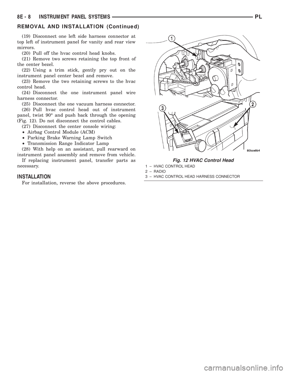
(26) Pull hvac control head out of instrument
panel, twist 90É and push back through the opening
(Fig. 12). Do not disconnect the control cables.
(27) Disconnect the center console wiring:
²Airbag Control Module (ACM)
²Parking Brake Warning Lamp Switch
²Transmission Range Indicator Lamp
(28) With help on an assistant, pull rearward on
instrument panel assembly and remove from vehicle.
If replacing instrument panel, transfer parts as
necessary.
INSTALLATION
For installation, reverse the above procedures.
Fig. 12 HVAC Control Head
1 ± HVAC CONTROL HEAD
2 ± RADIO
3 ± HVAC CONTROL HEAD HARNESS CONNECTOR
8E - 8 INSTRUMENT PANEL SYSTEMSPL
REMOVAL AND INSTALLATION (Continued)
Page 286 of 1285
VEHICLE SPEED CONTROL SYSTEM
TABLE OF CONTENTS
page page
DESCRIPTION AND OPERATION
SPEED CONTROL SYSTEM.................1
SPEED CONTROL SERVO-PCM OUTPUT.......2
SPEED CONTROL SWITCHESÐPCM INPUT....2
STOP LAMP SWITCH......................3
SERVO CABLE...........................3
VACUUM RESERVOIR.....................3VEHICLE SPEED SENSOR..................3
REMOVAL AND INSTALLATION
SPEED CONTROL SERVO...................3
SPEED CONTROL SWITCH..................4
SPEED CONTROL SERVO CABLE.............4
VACUUM RESERVOIR.....................5
DESCRIPTION AND OPERATION
SPEED CONTROL SYSTEM
OPERATION
The speed control system is electronically con-
trolled and vacuum operated. The electronic control
is integrated into the Powertrain Control Module
which is located in the engine compartment. The con-
trols are located on the steering wheel and consist of
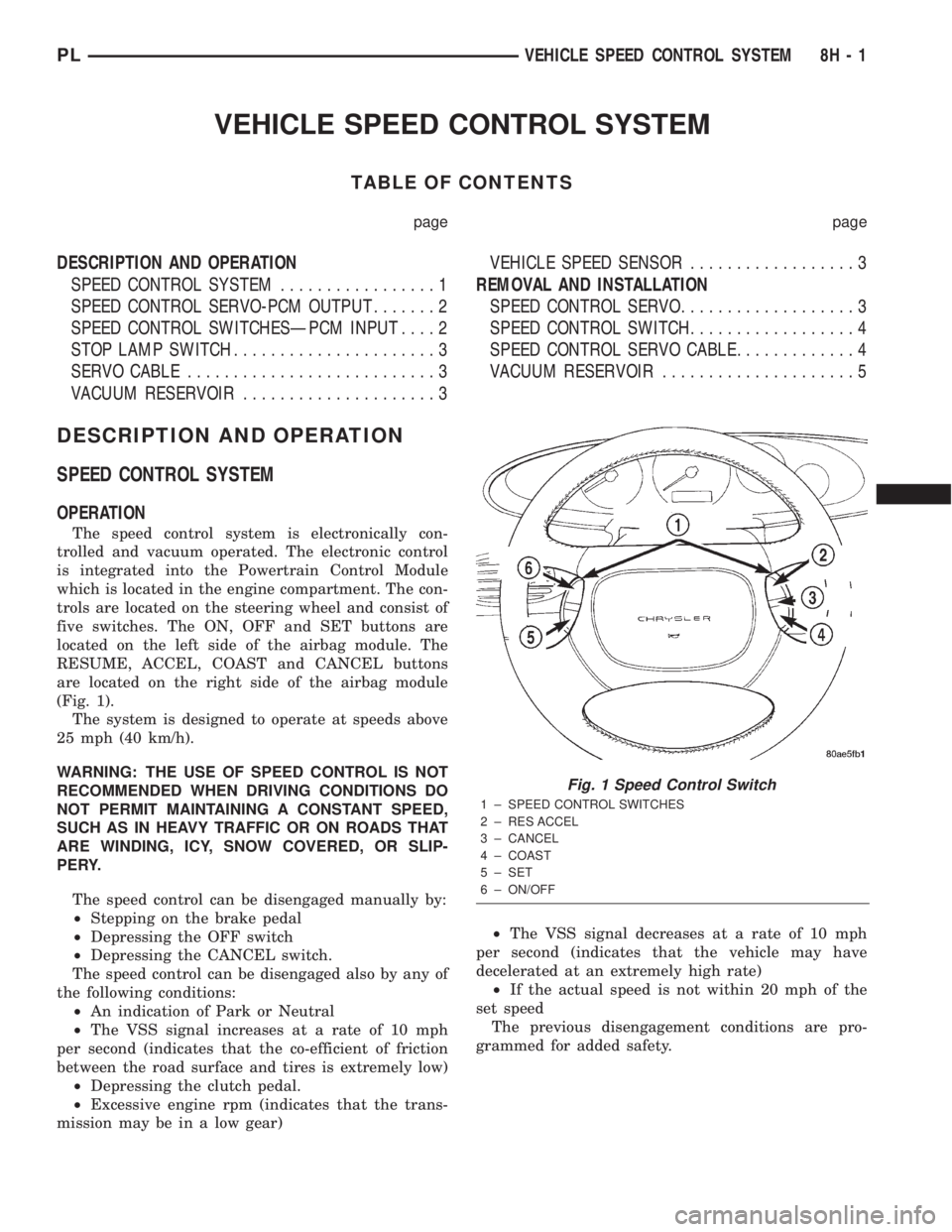
five switches. The ON, OFF and SET buttons are
located on the left side of the airbag module. The
RESUME, ACCEL, COAST and CANCEL buttons
are located on the right side of the airbag module
(Fig. 1).
The system is designed to operate at speeds above
25 mph (40 km/h).
WARNING: THE USE OF SPEED CONTROL IS NOT
RECOMMENDED WHEN DRIVING CONDITIONS DO
NOT PERMIT MAINTAINING A CONSTANT SPEED,
SUCH AS IN HEAVY TRAFFIC OR ON ROADS THAT
ARE WINDING, ICY, SNOW COVERED, OR SLIP-
PERY.
The speed control can be disengaged manually by:
²Stepping on the brake pedal
²Depressing the OFF switch
²Depressing the CANCEL switch.
The speed control can be disengaged also by any of
the following conditions:
²An indication of Park or Neutral
²The VSS signal increases at a rate of 10 mph
per second (indicates that the co-efficient of friction
between the road surface and tires is extremely low)
²Depressing the clutch pedal.
²Excessive engine rpm (indicates that the trans-
mission may be in a low gear)²The VSS signal decreases at a rate of 10 mph
per second (indicates that the vehicle may have
decelerated at an extremely high rate)
²If the actual speed is not within 20 mph of the
set speed
The previous disengagement conditions are pro-
grammed for added safety.
Fig. 1 Speed Control Switch
1 ± SPEED CONTROL SWITCHES
2 ± RES ACCEL
3 ± CANCEL
4 ± COAST
5 ± SET
6 ± ON/OFF
PLVEHICLE SPEED CONTROL SYSTEM 8H - 1
Page 287 of 1285
SPEED CONTROL SERVO-PCM OUTPUT
DESCRIPTION
The servo unit consists of a solenoid valve body,
and a vacuum chamber. The solenoid valve body con-
tains three solenoids:
²Vacuum
²Vent
²Dump
The vacuum chamber contains a diaphragm with a
cable attached to control the throttle linkage.
OPERATION
The PCM controls the solenoid valve body. The
solenoid valve body controls the application and
release of vacuum to the diaphragm of the vacuum
servo. The servo unit cannot be repaired and is ser-
viced only as a complete assembly.
Power is supplied to the servo's by the PCM
through the brake switch. The PCM controls the
ground path for the vacuum and vent solenoids.
The dump solenoid is energized anytime it receives
power. If power to the dump solenoid is interrupted,
the solenoid dumps vacuum in the servo. This pro-
vides a safety backup to the vent and vacuum sole-
noids.
The vacuum and vent solenoids must be grounded
at the PCM to operate. When the PCM grounds the
vacuum servo solenoid, the solenoid allows vacuum
to enter the servo and pull open the throttle plate
using the cable. When the PCM breaks the ground,
the solenoid closes and no more vacuum is allowed to
enter the servo. The PCM also operates the vent sole-
noid via ground. The vent solenoid opens and closes a
passage to bleed or hold vacuum in the servo as
required.
The PCM duty cycles the vacuum and vent sole-
noids to maintain the set speed, or to accelerate and
decelerate the vehicle. To increase throttle opening,
the PCM grounds the vacuum and vent solenoids. To
decrease throttle opening, the PCM removes the
grounds from the vacuum and vent solenoids. When
the brake is released, if vehicle speed exceeds 25
mph to resume, 30 mph to set, and the RES/ACCEL
switch has been depressed, ground for the vent and
vacuum circuits is restored.
SPEED CONTROL SWITCHESÐPCM INPUT
Description
There are two separate switch pods that operate
the speed control system. The steering-wheel-
mounted switches use multiplexed circuits to provide
inputs to the PCM for ON, OFF, RESUME, ACCEL-
ERATE, SET, DECEL and CANCEL modes. Refer tothe owner's manual for more information on speed
control switch functions and setting procedures.
The individual switches cannot be repaired. If one
switch fails, the entire switch module must be
replaced.
Operation
When speed control is selected by depressing the
ON, OFF switch, the PCM allows a set speed to be
stored in RAM for speed control. To store a set speed,
depress the SET switch while the vehicle is moving
at a speed between 25 and 85 mph. In order for the
speed control to engage, the brakes cannot be
applied, nor can the gear selector be indicating the
transmission is in Park or Neutral.
Once the speed control has been disengaged,
depressing the ACCEL switch restores the vehicle to
the target speed that was stored in the PCM's RAM.
NOTE: Depressing the OFF switch will erase the
set speed stored in the PCM's RAM.
If, while the speed control is engaged, the driver
wishes to increase vehicle speed, the PCM is pro-
grammed for an acceleration feature. With the
ACCEL switch held closed, the vehicle accelerates
slowly to the desired speed. The new target speed is
stored in the RAM when the ACCEL switch is
released. The PCM also has a ªtap-upº feature in
which vehicle speed increases at a rate of approxi-
mately 2 mph for each momentary switch activation
of the ACCEL switch.
The PCM also provides a means to decelerate with-
out disengaging speed control. To decelerate from an
existing recorded target speed, depress and hold the
COAST switch until the desired speed is reached.
Then release the switch. The ON, OFF switch oper-
ates two components: the PCM's ON, OFF input, and
the battery voltage to the brake switch, which powers
the speed control servo.
Multiplexing
The PCM sends out 5 volts through a fixed resistor
and monitors the voltage change between the fixed
resistor and the switches. If none of the switches are
depressed, the PCM will measure 5 volts at the sen-
sor point (open circuit). If a switch with no resistor is
closed, the PCM will measure 0 volts (grounded cir-
cuit). Now, if a resistor is added to a switch, then the
PCM will measure some voltage proportional to the
size of the resistor. By adding a different resistor to
each switch, the PCM will see a different voltage
depending on which switch is pushed.
8H - 2 VEHICLE SPEED CONTROL SYSTEMPL
DESCRIPTION AND OPERATION (Continued)