2000 DODGE NEON instrument panel
[x] Cancel search: instrument panelPage 844 of 1285
1 second. Therefore, battery voltage is not supplied to
the fuel pump, ignition coil, fuel injectors and heated
oxygen sensors.
ENGINE START-UP MODE
This is an OPEN LOOP mode. If the vehicle is in
park or neutral (automatic transaxles) or the clutch
pedal is depressed (manual transaxles) the ignition
switch energizes the starter relay. The following
actions occur when the starter motor is engaged.
²If the PCM receives the camshaft position sensor
and crankshaft position sensor signals, it energizes
the Auto Shutdown (ASD) relay and fuel pump relay.
If the PCM does not receive both signals within
approximately one second, it will not energize the
ASD relay and fuel pump relay. The ASD and fuel
pump relays supply battery voltage to the fuel pump,
fuel injectors, ignition coil and heated oxygen sen-
sors.
²The PCM energizes the injectors (on the 69É
degree falling edge) for a calculated pulse width until
it determines crankshaft position from the camshaft
position sensor and crankshaft position sensor sig-
nals. The PCM determines crankshaft position within
1 engine revolution.
²After determining crankshaft position, the PCM
begins energizing the injectors in sequence. It adjusts
injector pulse width and controls injector synchroni-
zation by turning the individual ground paths to the
injectors On and Off.
²When the engine idles within664 RPM of its
target RPM, the PCM compares current MAP sensor
value with the atmospheric pressure value received
during the Ignition Switch On (zero RPM) mode. If
the PCM does not detect a minimum difference
between the two values, it sets a MAP diagnostic
trouble code into memory.
Once the ASD and fuel pump relays have been
energized, the PCM determines injector pulse width
based on the following:
²Battery voltage
²Engine coolant temperature
²Engine RPM
²Intake air temperature (IAT)
²Throttle position
²The number of engine revolutions since cranking
was initiated.
During Start-up the PCM maintains ignition tim-
ing at 9É BTDC.
ENGINE WARM-UP MODE
This is an OPEN LOOP mode. The following inputs
are received by the PCM:
²Engine coolant temperature
²Manifold Absolute Pressure (MAP)
²Intake air temperature (IAT)²Crankshaft position (engine speed)
²Camshaft position
²Knock sensor
²Throttle position
²A/C switch
²Battery voltage
²Power steering pressure switch
²Vehicle speed
²Speed control
²O2 sensors
²All diagnostics
The PCM adjusts injector pulse width and controls
injector synchronization by turning the individual
ground paths to the injectors On and Off.
The PCM adjusts ignition timing and engine idle
speed. Engine idle speed is adjusted through the idle
air control motor.
CRUISE OR IDLE MODE
When the engine is at operating temperature this
is a CLOSED LOOP mode. During cruising or idle
the following inputs are received by the PCM:
²Intake air temperature
²Engine coolant temperature
²Manifold absolute pressure
²Crankshaft position (engine speed)
²Camshaft position
²Knock sensor
²Throttle position
²Exhaust gas oxygen content
²A/C control positions
²Power steering pressure switch
²Battery voltage
²Vehicle speed
The PCM adjusts injector pulse width and controls
injector synchronization by turning the individual
ground paths to the injectors On and Off.
The PCM adjusts engine idle speed and ignition
timing. The PCM adjusts the air/fuel ratio according
to the oxygen content in the exhaust gas (measured
by the upstream and downstream heated oxygen sen-
sor).
The PCM monitors for engine misfire. During
active misfire and depending on the severity, the
PCM either continuously illuminates or flashes the
malfunction indicator lamp (Check Engine light on
instrument panel). Also, the PCM stores an engine
misfire DTC in memory.
The PCM performs several diagnostic routines.
They include:
²Oxygen sensor monitor
²Downstream heated oxygen sensor diagnostics
during open loop operation (except for shorted)
²Fuel system monitor
²EGR monitor
²Purge system monitor
PLFUEL SYSTEM 14 - 23
DESCRIPTION AND OPERATION (Continued)
Page 848 of 1285
As the engine enters one of these cells the PCM
looks at the amount of short term correction being
used. Because the goal is to keep short term at 0 (O2
Sensor switching at 0.5 volt), long term will update
in the same direction as short term correction was
moving to bring the short term back to 0. Once short
term is back at 0, this long term correction factor is
stored in memory.
The values stored in long term adaptive memory
are used for all operating conditions, including open
loop. However, the updating of the long term memoryoccurs after the engine has exceeded approximately
17É F, with fuel control in closed loop and two min-
utes of engine run time. This is done to prevent any
transitional temperature or start-up compensations
from corrupting long term fuel correction.
Long term adaptive memory can change the pulse-
width by as much as 25%, which means it can correct
for all of short term. It is possible to have a problem
that would drive long term to 25% and short term to
another 25% for a total change of 50% away from
base pulse-width calculation.
TYPICAL ADAPTIVE MEMORY FUEL CELLS
Open
ThrottleOpen
ThrottleOpen
ThrottleOpen
ThrottleOpen
ThrottleOpen
Throttle Idle Decel
Vacuum 20 17 13 9 5 0
Above 1,984
rpm1 3 5 7 9 11 13 Drive 15
Below 1,984
rpm02 4 6 8 1012
Neutral14
MAP volt =0 1.4 2.0 2.6 3.3 3.9
Fuel Correction Diagnostics
There are two fuel correction diagnostic routines:
²Fuel System Rich
²Fuel System Lean
A DTC is set and the MIL is illuminated if the
PCM detects either of these conditions.
PROGRAMMABLE COMMUNICATIONS
INTERFACE (PCI) BUS
OPERATION
Various modules exchange information through a
communications port called the PCI Bus. The Power-
train Control Module (PCM) transmits the Malfunc-
tion Indicator Lamp (Check Engine) On/Off signal
and engine RPM on the PCI Bus. The PCM receives
the Air Conditioning select input, transaxle gear
position inputs over the PCI Bus. The PCM also
receives the air conditioning evaporator temperature
signal from the PCI Bus.
The following components access or send informa-
tion on the PCI Bus.
²Instrument Panel
²Body Control Module
²Air Bag System Diagnostic Module
²Full ATC Display Head
²ABS Module
²Transmission Control Module
²Powertrain Control Module
²Overhead Travel Module
AIR CONDITIONING PRESSURE
TRANSDUCERÐPCM INPUT
OPERATION
The Powertrain Control Module (PCM) monitors
the A/C compressor discharge (high side) pressure
through the air conditioning pressure transducer.
The transducer supplies an input to the PCM. The
PCM engages the A/C compressor clutch if pressure
is sufficient for A/C system operation.
AUTOMATIC SHUTDOWN (ASD) SENSEÐPCM
INPUT
OPERATION
The ASD sense circuit informs the PCM when the
ASD relay energizes. A 12 volt signal at this input
indicates to the PCM that the ASD has been acti-
vated. This input is used only to sense that the ASD
relay is energized.
When energized, the ASD relay supplies battery
voltage to the fuel injectors, ignition coils and the
heating element in each oxygen sensor. If the PCM
does not receive 12 volts from this input after
grounding the ASD relay, it sets a Diagnostic Trouble
Code (DTC).
PLFUEL SYSTEM 14 - 27
DESCRIPTION AND OPERATION (Continued)
Page 852 of 1285
OPERATION
The combination coolant temperature sensor has
two elements. One element supplies coolant temper-
ature signal to the PCM. The other element supplies
coolant temperature signal to the instrument panel
gauge cluster. The PCM determines engine coolant
temperature from the coolant temperature sensor.
As coolant temperature varies the coolant temper-
ature sensors resistance changes resulting in a differ-
ent input voltage to the PCM and the instrument
panel gauge cluster.When the engine is cold, the PCM will provide
slightly richer air- fuel mixtures and higher idle
speeds until normal operating temperatures are
reached.
The PCM has a dual temperature range program
for better sensor accuracy at cold temperatures. At
key-ON the PCM sends a regulated five volt signal
through a 10,000 ohm resistor to the sensor. When
the sensed voltage reaches approximately 1.25 volts
the PCM turns on the transistor. The transistor con-
nects a 1,000 ohm resistor in parallel with the 10,000
ohm resistor. With this drop in resistance the PCM
recognizes an increase in voltage on the input circuit.
FUEL LEVEL SENSORÐPCM INPUT
DESCRIPTION
The fuel gauge level sending unit is attached to the
fuel pump module.
OPERATION
The fuel level sensor (fuel gauge sending unit)
sends a signal to the PCM to indicate fuel level. The
purpose of this feature is to prevent a false setting of
misfire and fuel system monitor trouble codes if the
fuel level is less than approximately 15 percent of its
rated capacity. It is also used to send a signal for fuel
gauge operation via the PCI bus circuits.
Fig. 9 Timing Reference Notches
1 ± MACHINED NOTCHES
2 ± CRANKSHAFT POSITION SENSOR
Fig. 10 Engine Coolant Temperature SensorÐSOHC
1 ± ENGINE COOLANT TEMPERATURE SENSOR
2 ± CAMSHAFT POSITION SENSOR
PLFUEL SYSTEM 14 - 31
DESCRIPTION AND OPERATION (Continued)
Page 859 of 1285
Like all Hall-effect sensors, the electronics of the
sensor needs a power source. This power source is
provided by the PCM. It is the same 8 volt power
supply that is used by the CKP and CMP sensors.
The vehicle speed sensor generates 8 pulses per
sensor revolution. This signal, in conjunction with a
closed throttle signal from the throttle position sen-
sor, indicates a closed throttle deceleration to the
PCM. Under deceleration conditions, the PCM
adjusts the Idle Air Control (IAC) motor to maintain
a desired MAP value.
When the vehicle is stopped at idle, a closed throt-
tle signal is received by the PCM (but a speed sensor
signal is not received). Under idle conditions, the
PCM adjusts the IAC motor to maintain a desired
engine speed.
AIR CONDITIONING CLUTCH RELAYÐPCM
OUTPUT
DESCRIPTION
The air conditioning clutch relay is located in the
PDC. The inside top of the PDC cover has a label
showing relay and fuse location.
OPERATION
The PCM controls the air conditioning clutch relay
ground circuit. The A/C clutch relay coil side contains
a 10 amp fuse between the buss bar in the Power
Distribution Center (PDC) and the relay. The power
side of this relay is fused with a 40 amp fuse. When
the PCM receives an air conditioning input, it
grounds the A/C compressor clutch relay and the
radiator fan relay.
When the PCM senses low idle speeds or wide open
throttle through the throttle position sensor, it
removes the ground for the A/C compressor clutch
relay. When the relay de-energizes, the contacts open
preventing air conditioning clutch engagement. Also,
if the PCM senses a part throttle launch condition, it
disables the A/C compressor clutch for several sec-
onds.
AUTOMATIC SHUTDOWN RELAYÐPCM
OUTPUT
DESCRIPTION
The ASD relay is located in the PDC. The inside
top of the PDC cover has a label showing relay and
fuse location.
OPERATION
The automatic shutdown (ASD) relay supplies bat-
tery voltage to the fuel injectors, electronic ignition
coil and the heating elements in the oxygen sensors
generator field and PCM sense circuit.A buss bar in the power distribution center (PDC)
supplies voltage to the solenoid side and contact side
of the relay. The ASD relay power circuit contains a
fuse between the buss bar in the PDC and the relay.
The fuse also protects the power circuit for the fuel
pump relay and pump. The fuse is located in the
PDC. Refer to the Wiring Diagrams for circuit infor-
mation.
The PCM controls the relay by switching the
ground path for the solenoid side of the relay on and
off. The PCM turns the ground path off when the
ignition switch is in the Off position unless the 02
Heater Monitor test is being run. When the ignition
switch is in the On or Crank position, the PCM mon-
itors the crankshaft position sensor and camshaft
position sensor signals to determine engine speed
and ignition timing (coil dwell). If the PCM does not
receive the crankshaft position sensor and camshaft
position sensor signals when the ignition switch is in
the Run position, it will de-energize the ASD relay.
CHARGING SYSTEM INDICATOR LAMPÐPCM
OUTPUT
OPERATION
The PCM turns the instrument panel Charging
System Lamp on. Refer to the Charging system sec-
tion information.
FUEL PUMP RELAYÐPCM OUTPUT
DESCRIPTION
The fuel pump relay is located in the PDC. The
inside top of the PDC cover has a label showing relay
and fuse location.
OPERATION
The fuel pump relay supplies battery voltage to the
fuel pump. A buss bar in the Power Distribution Cen-
ter (PDC) supplies voltage to the solenoid side and
contact side of the relay. The fuel pump relay power
circuit contains a fuse between the buss bar in the
PDC and the relay. The fuse also protects the power
circuit for the Automatic Shutdown (ASD) relay. The
fuse is located in the PDC. Refer to the Wiring Dia-
grams for circuit information.
The PCM controls the fuel pump relay by switch-
ing the ground path for the solenoid side of the relay
on and off. The PCM turns the ground path off when
the ignition switch is in the Off position. When the
ignition switch is in the On position, the PCM ener-
gizes the fuel pump. If the crankshaft position sensor
does not detect engine rotation, the PCM de-ener-
gizes the relay after approximately one second.
14 - 38 FUEL SYSTEMPL
DESCRIPTION AND OPERATION (Continued)
Page 861 of 1285
DATA LINK CONNECTOR
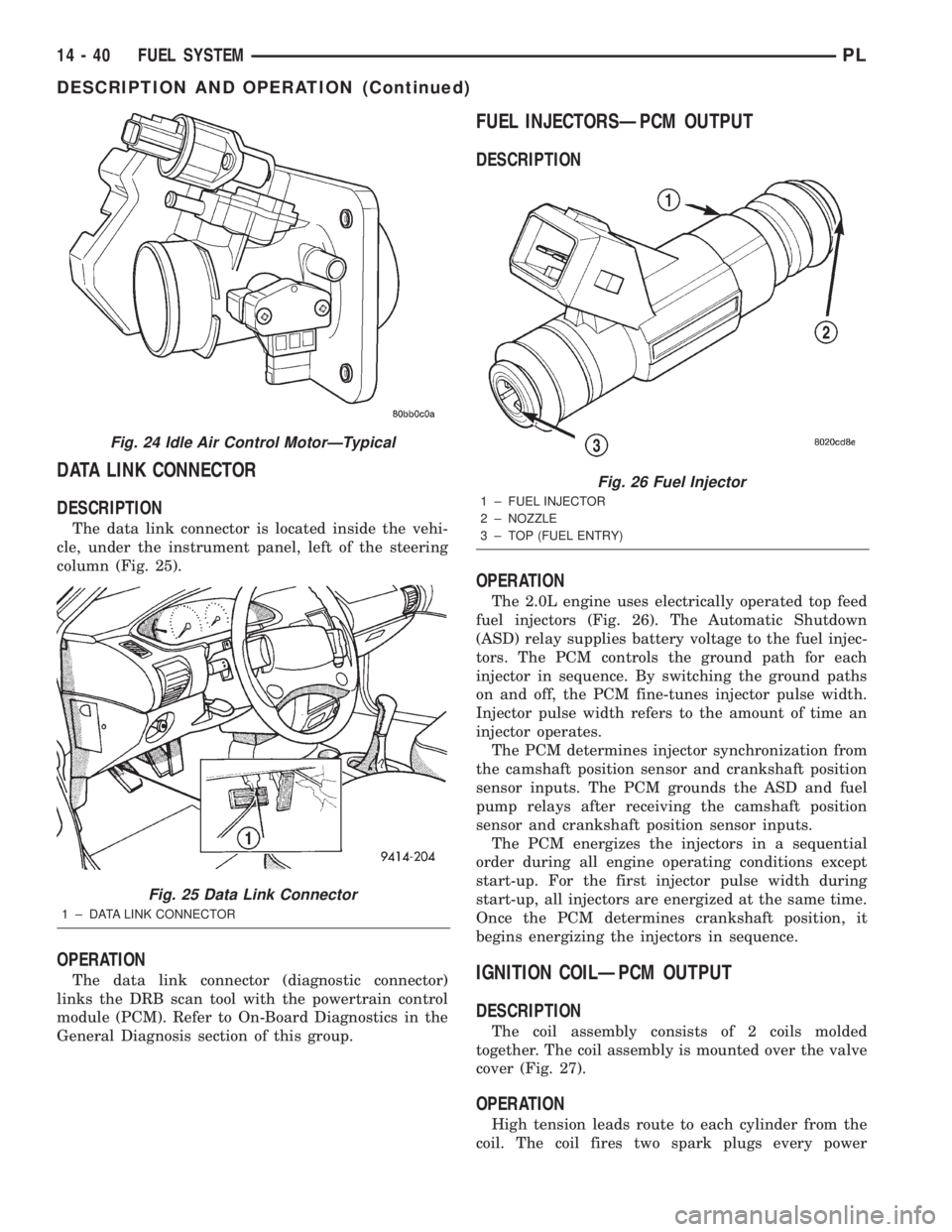
DESCRIPTION
The data link connector is located inside the vehi-
cle, under the instrument panel, left of the steering
column (Fig. 25).
OPERATION
The data link connector (diagnostic connector)
links the DRB scan tool with the powertrain control
module (PCM). Refer to On-Board Diagnostics in the
General Diagnosis section of this group.
FUEL INJECTORSÐPCM OUTPUT
DESCRIPTION
OPERATION
The 2.0L engine uses electrically operated top feed
fuel injectors (Fig. 26). The Automatic Shutdown
(ASD) relay supplies battery voltage to the fuel injec-
tors. The PCM controls the ground path for each
injector in sequence. By switching the ground paths
on and off, the PCM fine-tunes injector pulse width.
Injector pulse width refers to the amount of time an
injector operates.
The PCM determines injector synchronization from
the camshaft position sensor and crankshaft position
sensor inputs. The PCM grounds the ASD and fuel
pump relays after receiving the camshaft position
sensor and crankshaft position sensor inputs.
The PCM energizes the injectors in a sequential
order during all engine operating conditions except
start-up. For the first injector pulse width during
start-up, all injectors are energized at the same time.
Once the PCM determines crankshaft position, it
begins energizing the injectors in sequence.
IGNITION COILÐPCM OUTPUT
DESCRIPTION
The coil assembly consists of 2 coils molded
together. The coil assembly is mounted over the valve
cover (Fig. 27).
OPERATION
High tension leads route to each cylinder from the
coil. The coil fires two spark plugs every power
Fig. 24 Idle Air Control MotorÐTypical
Fig. 25 Data Link Connector
1 ± DATA LINK CONNECTOR
Fig. 26 Fuel Injector
1 ± FUEL INJECTOR
2 ± NOZZLE
3 ± TOP (FUEL ENTRY)
14 - 40 FUEL SYSTEMPL
DESCRIPTION AND OPERATION (Continued)
Page 862 of 1285
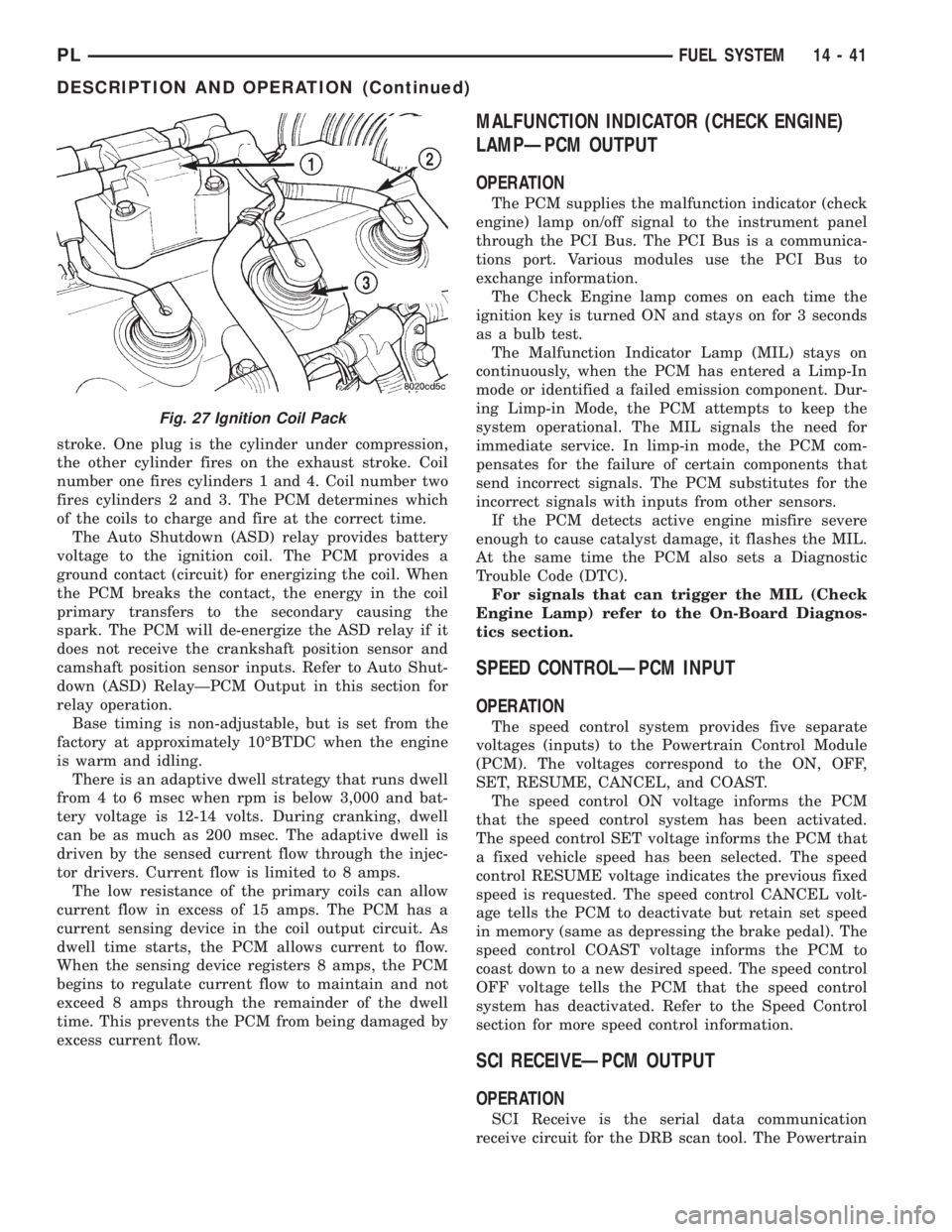
stroke. One plug is the cylinder under compression,
the other cylinder fires on the exhaust stroke. Coil
number one fires cylinders 1 and 4. Coil number two
fires cylinders 2 and 3. The PCM determines which
of the coils to charge and fire at the correct time.
The Auto Shutdown (ASD) relay provides battery
voltage to the ignition coil. The PCM provides a
ground contact (circuit) for energizing the coil. When
the PCM breaks the contact, the energy in the coil
primary transfers to the secondary causing the
spark. The PCM will de-energize the ASD relay if it
does not receive the crankshaft position sensor and
camshaft position sensor inputs. Refer to Auto Shut-
down (ASD) RelayÐPCM Output in this section for
relay operation.
Base timing is non-adjustable, but is set from the
factory at approximately 10ÉBTDC when the engine
is warm and idling.
There is an adaptive dwell strategy that runs dwell
from 4 to 6 msec when rpm is below 3,000 and bat-
tery voltage is 12-14 volts. During cranking, dwell
can be as much as 200 msec. The adaptive dwell is
driven by the sensed current flow through the injec-
tor drivers. Current flow is limited to 8 amps.
The low resistance of the primary coils can allow
current flow in excess of 15 amps. The PCM has a
current sensing device in the coil output circuit. As
dwell time starts, the PCM allows current to flow.
When the sensing device registers 8 amps, the PCM
begins to regulate current flow to maintain and not
exceed 8 amps through the remainder of the dwell
time. This prevents the PCM from being damaged by
excess current flow.
MALFUNCTION INDICATOR (CHECK ENGINE)
LAMPÐPCM OUTPUT
OPERATION
The PCM supplies the malfunction indicator (check
engine) lamp on/off signal to the instrument panel
through the PCI Bus. The PCI Bus is a communica-
tions port. Various modules use the PCI Bus to
exchange information.
The Check Engine lamp comes on each time the
ignition key is turned ON and stays on for 3 seconds
as a bulb test.
The Malfunction Indicator Lamp (MIL) stays on
continuously, when the PCM has entered a Limp-In
mode or identified a failed emission component. Dur-
ing Limp-in Mode, the PCM attempts to keep the
system operational. The MIL signals the need for
immediate service. In limp-in mode, the PCM com-
pensates for the failure of certain components that
send incorrect signals. The PCM substitutes for the
incorrect signals with inputs from other sensors.
If the PCM detects active engine misfire severe
enough to cause catalyst damage, it flashes the MIL.
At the same time the PCM also sets a Diagnostic
Trouble Code (DTC).
For signals that can trigger the MIL (Check
Engine Lamp) refer to the On-Board Diagnos-
tics section.
SPEED CONTROLÐPCM INPUT
OPERATION
The speed control system provides five separate
voltages (inputs) to the Powertrain Control Module
(PCM). The voltages correspond to the ON, OFF,
SET, RESUME, CANCEL, and COAST.
The speed control ON voltage informs the PCM
that the speed control system has been activated.
The speed control SET voltage informs the PCM that
a fixed vehicle speed has been selected. The speed
control RESUME voltage indicates the previous fixed
speed is requested. The speed control CANCEL volt-
age tells the PCM to deactivate but retain set speed
in memory (same as depressing the brake pedal). The
speed control COAST voltage informs the PCM to
coast down to a new desired speed. The speed control
OFF voltage tells the PCM that the speed control
system has deactivated. Refer to the Speed Control
section for more speed control information.
SCI RECEIVEÐPCM OUTPUT
OPERATION
SCI Receive is the serial data communication
receive circuit for the DRB scan tool. The Powertrain
Fig. 27 Ignition Coil Pack
PLFUEL SYSTEM 14 - 41
DESCRIPTION AND OPERATION (Continued)
Page 897 of 1285
(7) Using a soft face hammer, tap the front suspen-
sion crossmember back-and-forth or side-to-side until
it is aligned with the previously scribed positioning
marks on the body of the vehicle (Fig. 9). Once the
front suspension crossmember is correctly positioned,
tighten the rear two crossmember (and rear lower
control arm) mounting bolts to a torque of 203 N´m
(150 ft. lbs.), then tighten the front two crossmember
mounting bolts to a torque of 142 N´m (105 ft. lbs.).
(8) Fasten the engine torque strut to the right for-
ward corner of the front suspension crossmember
using its mounting bolt (Fig. 8). Follow the procedure
described in the ENGINE service manual group to
properly align and tighten the torque strut and it's
mounting bolts.
(9) Using a lint free towel, wipe clean the open
power steering hose ends and the power steering
gear ports. Replace the pressure hose used O-ring
with new. Lubricate the O-ring with power steering
fluid.
(10) Attach the power steering fluid pressure hose
to it's port on the power steering gear (Fig. 7). Start
the tube nut threads into the gear, but do not tighten
them at this time. On vehicles equipped with a power
steering fluid cooler, reconnect the cooler line to the
gear in place of the power steering fluid return hose.
(11) Open the routing clips on the front of the
steering gear housing and install the power steering
fluid pressure hose into the routing clips.
(12) On vehicles equipped with a power steering
fluid cooler, place the cooler in mounting position and
snap the cooler tube going to the gear into the right
routing clip.
(13) Close both routing clips.
(14) Tighten the power steering fluid pressure
hose tube nut at the gear to a torque of 34 N´m (25
ft. lbs.).
(15) If the vehicle is equipped with a power steer-
ing fluid cooler, install the two screws securing the
cooler to the front suspension crossmember. They are
located behind the cooler.
(16) On vehicle's with a power steering fluid cooler,
place the hose clamp on the hose far enough from the
end to clear the steel fitting on the gear. Do the same
for the fluid return hose on a vehicle that is not
equipped with a cooler.
(17) Push either hose listed in the above step onto
the steel fitting, then move and secure the clamp on
the hose past the bead on the steel fitting in the
steering gears outlet port (Fig. 7).
(18) Route the fluid return hose along the front of
the steering gear, clipping it into place in the
C-clamps on the outside of the routing clips on the
front of the power steering gear housing.
(19) Reconnect the wiring harness connector from
the power steering fluid pressure switch (Fig. 6). Besure the locking tab on the wiring harness connector
is securely latched.
(20) Perform the following to each outer tie rod:
²Place the tie rod heat shield on the knuckle's
steering arm, aligning the hole in the shield with the
hole in the knuckle and the tangs on the outside of
the shield with the outside configuration of the steer-
ing arm. The shield should now be facing outboard,
away from the power steering gear and tie rod (Fig.
4).
²Attach the outer tie rod end to its steering
knuckle.
²Start the attaching nut onto the stud of the
outer tie rod.
²While holding the stud of the tie rod stationary
with a wrench, tighten the attaching nut (Fig. 4).
²Using a crowfoot wrench attached to a torque
wrench, tighten the attaching nut to 55 N´m (40 ft.
lbs.).
(21) Install the tire and wheel assemblies back on
vehicle. Tighten the wheel mounting nuts to 135 N´m
(100 ft. lbs.) torque.
(22) Lower the vehicle to ground level.
(23) Install the dash-to-lower coupling seal in
place over the lower coupling's plastic collar.
NOTE: Verify that grease is present on the lip of
the dash-to-coupling seal where it contacts the cou-
pling's plastic collar.
(24) Inside the passenger compartment, reconnect
the steering column lower coupling to the steering
column upper coupling (Fig. 3). Install the coupling
pinch bolt and tighten the pinch bolt nut to a torque
of 28 N´m (250 in. lbs.). Install the pinch bolt
retainer pin.
(25) Remove the steering wheel holder.
(26) While looking under the instrument panel at
the lower coupling, rotate the steering wheel back-
and-forth to verify that the lower coupling does not
squeak against the dash-to-coupling seal.
(27) Perform the POWER STEERING PUMP INI-
TIAL OPERATION service procedure which can be
found in the POWER STEERING PUMP section of
this group to properly fill and bleed the power steer-
ing system.
(28) Check for fluid leaks.
(29) Adjust the front toe setting on the vehicle.
Refer to WHEEL ALIGNMENT in the SUSPENSION
service manual group.
OUTER TIE ROD
REMOVAL
(1) Raise the vehicle. Refer to HOISTING in the
LUBRICATION AND MAINTENANCE group in this
service manual for the correct lifting procedure.
19 - 26 STEERINGPL
REMOVAL AND INSTALLATION (Continued)
Page 903 of 1285
REMOVAL
(1) Disconnect the negative (-) cable from the bat-
tery and isolate the cable.
(2) Before beginning removal of the steering col-
umn, be sure the front wheels of vehicle are in the
STRAIGHT-AHEAD position.
(3) Remove the screw securing the left end of the
top cover to the instrument panel. It is located just
above the left instrument panel end cap.
(4) Starting on the driver's end, push upward on
the instrument panel top cover, disengaging its
retainer clips along the face of the instrument panel.
Disengage just enough clips to allow access to the
upper ends of the instrument cluster bezel.
(5) Disengage the clips along the outer edge of the
instrument cluster bezel and remove the bezel from
the vehicle.
(6) Remove the two screws along the bottom of the
steering column cover that mounts below the steering
column on the instrument panel. Disengage the clips
on the upper end of the steering column cover and
remove the cover by pulling it straight away from the
instrument panel.
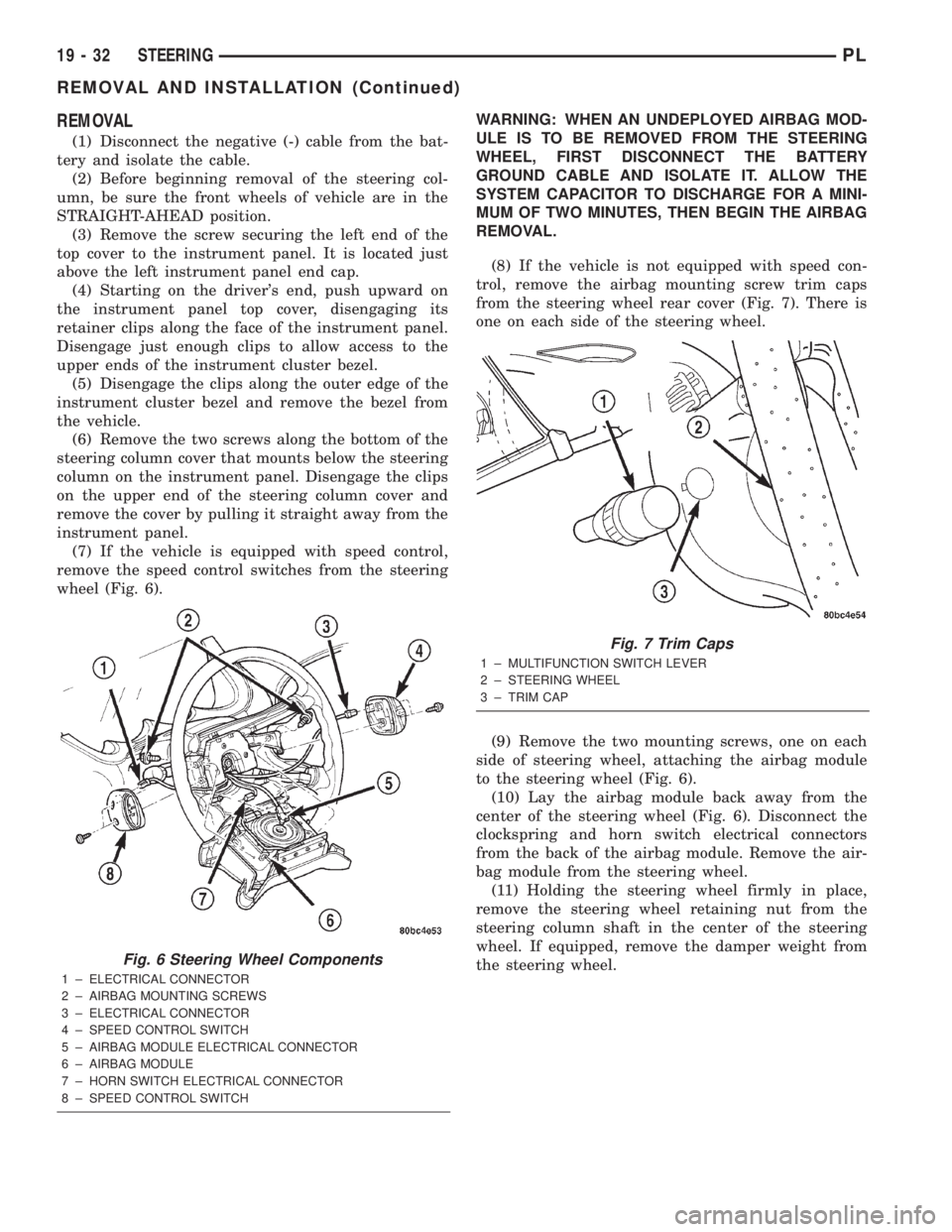
(7) If the vehicle is equipped with speed control,
remove the speed control switches from the steering
wheel (Fig. 6).WARNING: WHEN AN UNDEPLOYED AIRBAG MOD-
ULE IS TO BE REMOVED FROM THE STEERING
WHEEL, FIRST DISCONNECT THE BATTERY
GROUND CABLE AND ISOLATE IT. ALLOW THE
SYSTEM CAPACITOR TO DISCHARGE FOR A MINI-
MUM OF TWO MINUTES, THEN BEGIN THE AIRBAG
REMOVAL.
(8) If the vehicle is not equipped with speed con-
trol, remove the airbag mounting screw trim caps
from the steering wheel rear cover (Fig. 7). There is
one on each side of the steering wheel.
(9) Remove the two mounting screws, one on each
side of steering wheel, attaching the airbag module
to the steering wheel (Fig. 6).
(10) Lay the airbag module back away from the
center of the steering wheel (Fig. 6). Disconnect the
clockspring and horn switch electrical connectors
from the back of the airbag module. Remove the air-
bag module from the steering wheel.
(11) Holding the steering wheel firmly in place,
remove the steering wheel retaining nut from the
steering column shaft in the center of the steering
wheel. If equipped, remove the damper weight from
the steering wheel.
Fig. 6 Steering Wheel Components
1 ± ELECTRICAL CONNECTOR
2 ± AIRBAG MOUNTING SCREWS
3 ± ELECTRICAL CONNECTOR
4 ± SPEED CONTROL SWITCH
5 ± AIRBAG MODULE ELECTRICAL CONNECTOR
6 ± AIRBAG MODULE
7 ± HORN SWITCH ELECTRICAL CONNECTOR
8 ± SPEED CONTROL SWITCH
Fig. 7 Trim Caps
1 ± MULTIFUNCTION SWITCH LEVER
2 ± STEERING WHEEL
3 ± TRIM CAP
19 - 32 STEERINGPL
REMOVAL AND INSTALLATION (Continued)