2000 DODGE NEON instrument panel
[x] Cancel search: instrument panelPage 710 of 1285
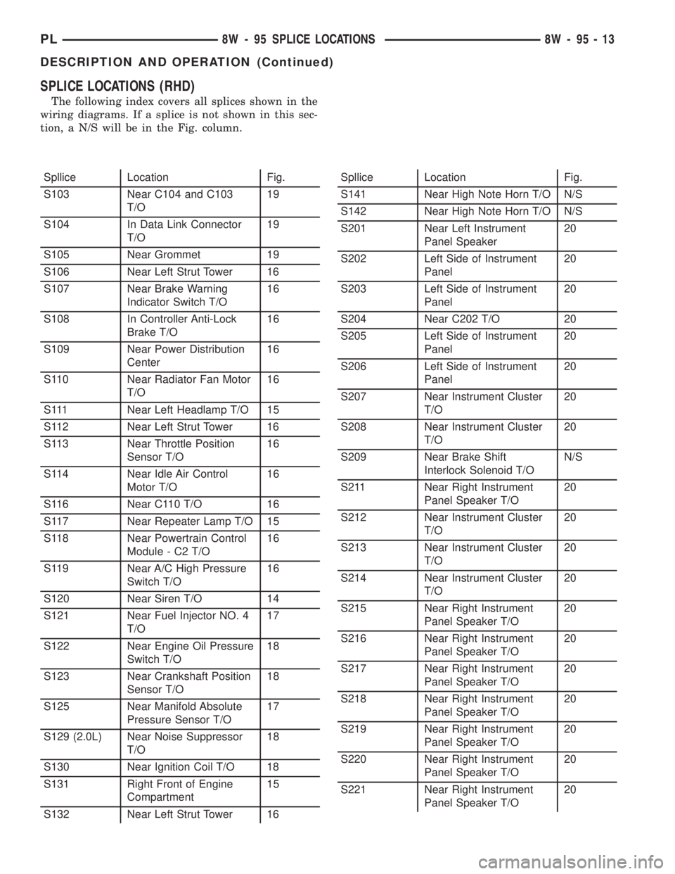
SPLICE LOCATIONS (RHD)
The following index covers all splices shown in the
wiring diagrams. If a splice is not shown in this sec-
tion, a N/S will be in the Fig. column.
Spllice Location Fig.
S103 Near C104 and C103
T/O19
S104 In Data Link Connector
T/O19
S105 Near Grommet 19
S106 Near Left Strut Tower 16
S107 Near Brake Warning
Indicator Switch T/O16
S108 In Controller Anti-Lock
Brake T/O16
S109 Near Power Distribution
Center16
S110 Near Radiator Fan Motor
T/O16
S111 Near Left Headlamp T/O 15
S112 Near Left Strut Tower 16
S113 Near Throttle Position
Sensor T/O16
S114 Near Idle Air Control
Motor T/O16
S116 Near C110 T/O 16
S117 Near Repeater Lamp T/O 15
S118 Near Powertrain Control
Module - C2 T/O16
S119 Near A/C High Pressure
Switch T/O16
S120 Near Siren T/O 14
S121 Near Fuel Injector NO. 4
T/O17
S122 Near Engine Oil Pressure
Switch T/O18
S123 Near Crankshaft Position
Sensor T/O18
S125 Near Manifold Absolute
Pressure Sensor T/O17
S129 (2.0L) Near Noise Suppressor
T/O18
S130 Near Ignition Coil T/O 18
S131 Right Front of Engine
Compartment15
S132 Near Left Strut Tower 16Spllice Location Fig.
S141 Near High Note Horn T/O N/S
S142 Near High Note Horn T/O N/S
S201 Near Left Instrument
Panel Speaker20
S202 Left Side of Instrument
Panel20
S203 Left Side of Instrument
Panel20
S204 Near C202 T/O 20
S205 Left Side of Instrument
Panel20
S206 Left Side of Instrument
Panel20
S207 Near Instrument Cluster
T/O20
S208 Near Instrument Cluster
T/O20
S209 Near Brake Shift
Interlock Solenoid T/ON/S
S211 Near Right Instrument
Panel Speaker T/O20
S212 Near Instrument Cluster
T/O20
S213 Near Instrument Cluster
T/O20
S214 Near Instrument Cluster
T/O20
S215 Near Right Instrument
Panel Speaker T/O20
S216 Near Right Instrument
Panel Speaker T/O20
S217 Near Right Instrument
Panel Speaker T/O20
S218 Near Right Instrument
Panel Speaker T/O20
S219 Near Right Instrument
Panel Speaker T/O20
S220 Near Right Instrument
Panel Speaker T/O20
S221 Near Right Instrument
Panel Speaker T/O20
PL8W - 95 SPLICE LOCATIONS 8W - 95 - 13
DESCRIPTION AND OPERATION (Continued)
Page 711 of 1285
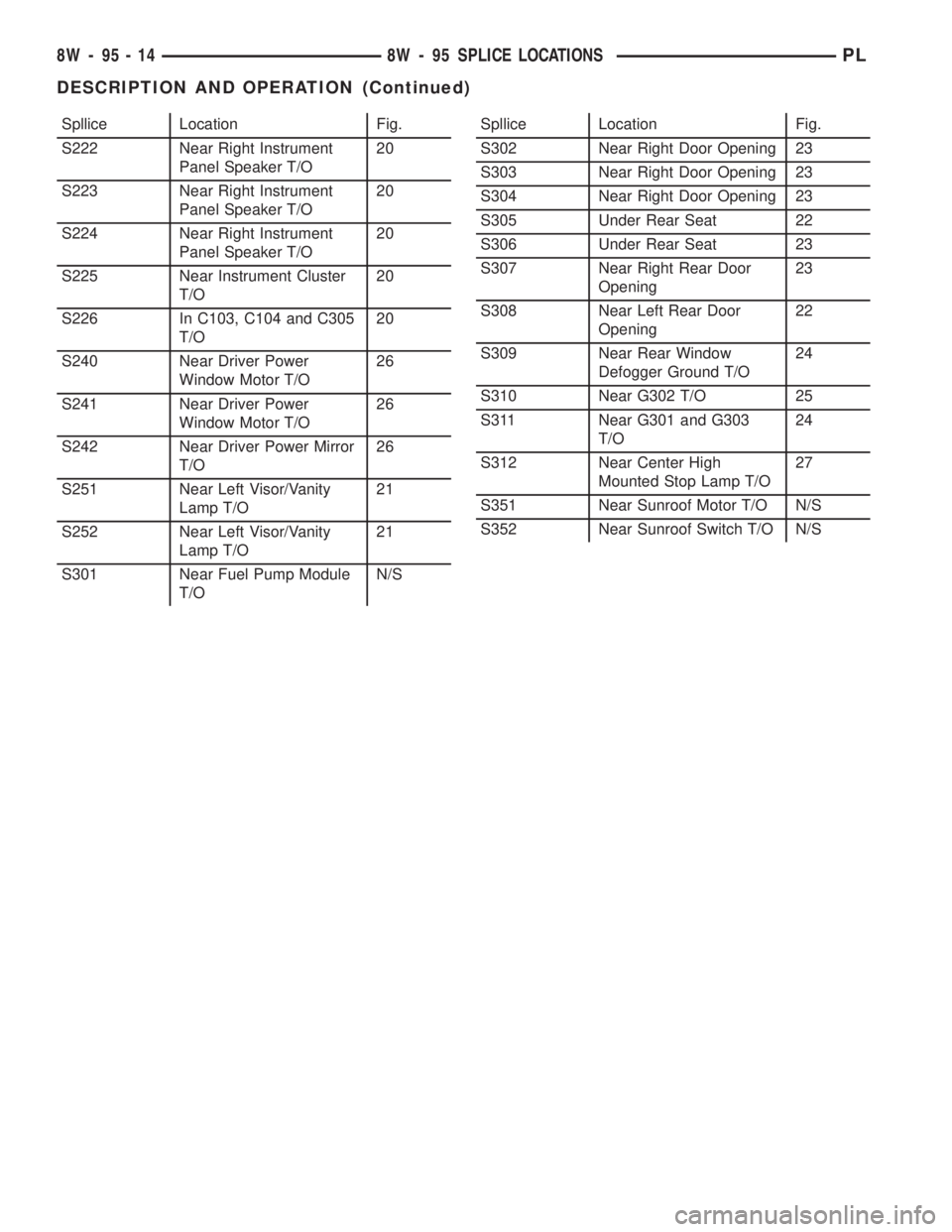
Spllice Location Fig.
S222 Near Right Instrument
Panel Speaker T/O20
S223 Near Right Instrument
Panel Speaker T/O20
S224 Near Right Instrument
Panel Speaker T/O20
S225 Near Instrument Cluster
T/O20
S226 In C103, C104 and C305
T/O20
S240 Near Driver Power
Window Motor T/O26
S241 Near Driver Power
Window Motor T/O26
S242 Near Driver Power Mirror
T/O26
S251 Near Left Visor/Vanity
Lamp T/O21
S252 Near Left Visor/Vanity
Lamp T/O21
S301 Near Fuel Pump Module
T/ON/SSpllice Location Fig.
S302 Near Right Door Opening 23
S303 Near Right Door Opening 23
S304 Near Right Door Opening 23
S305 Under Rear Seat 22
S306 Under Rear Seat 23
S307 Near Right Rear Door
Opening23
S308 Near Left Rear Door
Opening22
S309 Near Rear Window
Defogger Ground T/O24
S310 Near G302 T/O 25
S311 Near G301 and G303
T/O24
S312 Near Center High
Mounted Stop Lamp T/O27
S351 Near Sunroof Motor T/O N/S
S352 Near Sunroof Switch T/O N/S
8W - 95 - 14 8W - 95 SPLICE LOCATIONSPL
DESCRIPTION AND OPERATION (Continued)
Page 716 of 1285
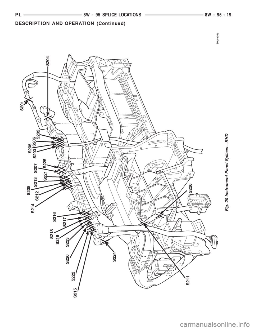
Fig. 20 Instrument Panel SplicesÐRHD
PL8W - 95 SPLICE LOCATIONS 8W - 95 - 19
DESCRIPTION AND OPERATION (Continued)
Page 750 of 1285
(8) Install lower engine torque strut. Refer to pro-
cedure in this section.
(9) Connect exhaust system to manifold. Refer to
Group 11, Exhaust System for procedure and torque
specifications.
(10) Connect the downstream oxygen sensor.
(11) Install A/C compressor and hoses. Refer to
Group 24, Heater and Air Conditioning for procedure.
(12) Install accessory drive belts. Refer to Group 7,
Cooling System Accessory Drive Section for belt ten-
sion adjustment.
(13) Install inner splash shield.
(14) Install wheels and lower vehicle.
(15) Install power steering pump and reservoir.
Refer to Group 7, Cooling System Accessory Drive
Section for belt tension adjustment.
(16)Manual Transmission:Connect clutch cable,
reverse light electrical connector and shift linkages.
Refer to Group 6, Clutch.
(17)Automatic Transmission:Connect shifter,
kickdown linkage and cooler lines. Refer to Group 21,
Transaxle for procedures.
(18) Connect fuel line and heater hoses.
(19)
Install all ground straps. Connect engine wiring
harness. Refer to Group 8, Electrical for procedure.
(20) Install lower radiator hose, fan module, and
upper radiator hose. Refer to Group 7, Cooling Sys-
tem for procedures
(21) Fill cooling system. Refer to Group 7, Cooling
System for filling procedure.
(22) Install battery tray and battery.
(23) Install air cleaner housing assembly and con-
nect intake duct to intake manifold.(24) Connect all throttle body electrical connectors
and linkage.
(25) Install oil filter. Fill engine crankcase with
proper oil to correct level.
(26) Perform camshaft and crankshaft timing
relearn procedure as follows:
²Connect the DRB scan tool to the data link
(diagnostic) connector. This connector is located in
the passenger compartment; at the lower edge of
instrument panel; near the steering column.
²Turn the ignition switch on and access the ªmis-
cellaneousº screen.
²Select ªre-learn cam/crankº option and follow
directions on DRB screen.
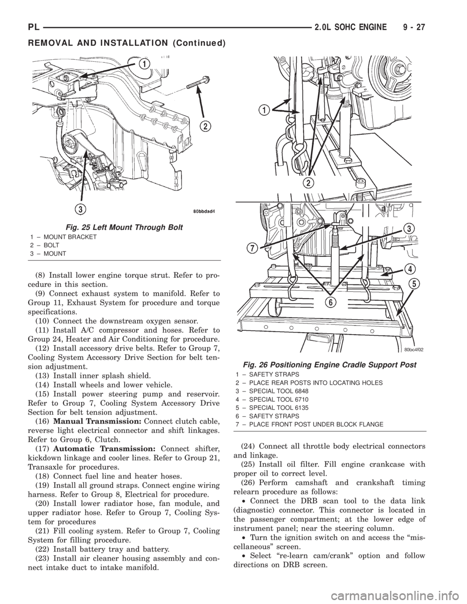
Fig. 25 Left Mount Through Bolt
1 ± MOUNT BRACKET
2 ± BOLT
3 ± MOUNT
Fig. 26 Positioning Engine Cradle Support Post
1 ± SAFETY STRAPS
2 ± PLACE REAR POSTS INTO LOCATING HOLES
3 ± SPECIAL TOOL 6848
4 ± SPECIAL TOOL 6710
5 ± SPECIAL TOOL 6135
6 ± SAFETY STRAPS
7 ± PLACE FRONT POST UNDER BLOCK FLANGE
PL2.0L SOHC ENGINE 9 - 27
REMOVAL AND INSTALLATION (Continued)
Page 757 of 1285
INSPECT CYLINDER HEAD FOR THE FOLLOWING:
NOTE:
²Check oil feed holes for blockage.
²Inspect cylinder head camshaft bearings for
wear, Refer to Cylinder Head, Inspection and Clean-
ing.
²Check camshaft bearing journals for scratches
and worn areas. If light scratches are present, they
may be removed with 400 grit sand paper. If deep
scratches are present, replace the camshaft and
check the cylinder head for damage. Replace the
cylinder head if worn or damaged. Check the lobes
for pitting and wear. If the lobes show signs of
wear, check the corresponding rocker arm roller for
wear or damage. Replace rocker arm/hydraulic lash
adjuster if worn or damaged. If lobes show signs of
pitting on the nose, flank or base circle; replace the
camshaft.
INSTALLATION
(1) Lubricate the camshaft journals with oil and
install camshaftwithoutrocker arm assemblies
installed.
(2) Install camshaft target magnet into the end of
the camshaft. Tighten mounting screw to 3.4 N´m (30
in. lbs.).
(3) Install camshaft position sensor and tighten
mounting screws to 9 N´m (80 in. lbs.).
(4) Measure camshaft end play using the following
procedure:
(a) Mount dial indicator C-3339 or equivalent, to
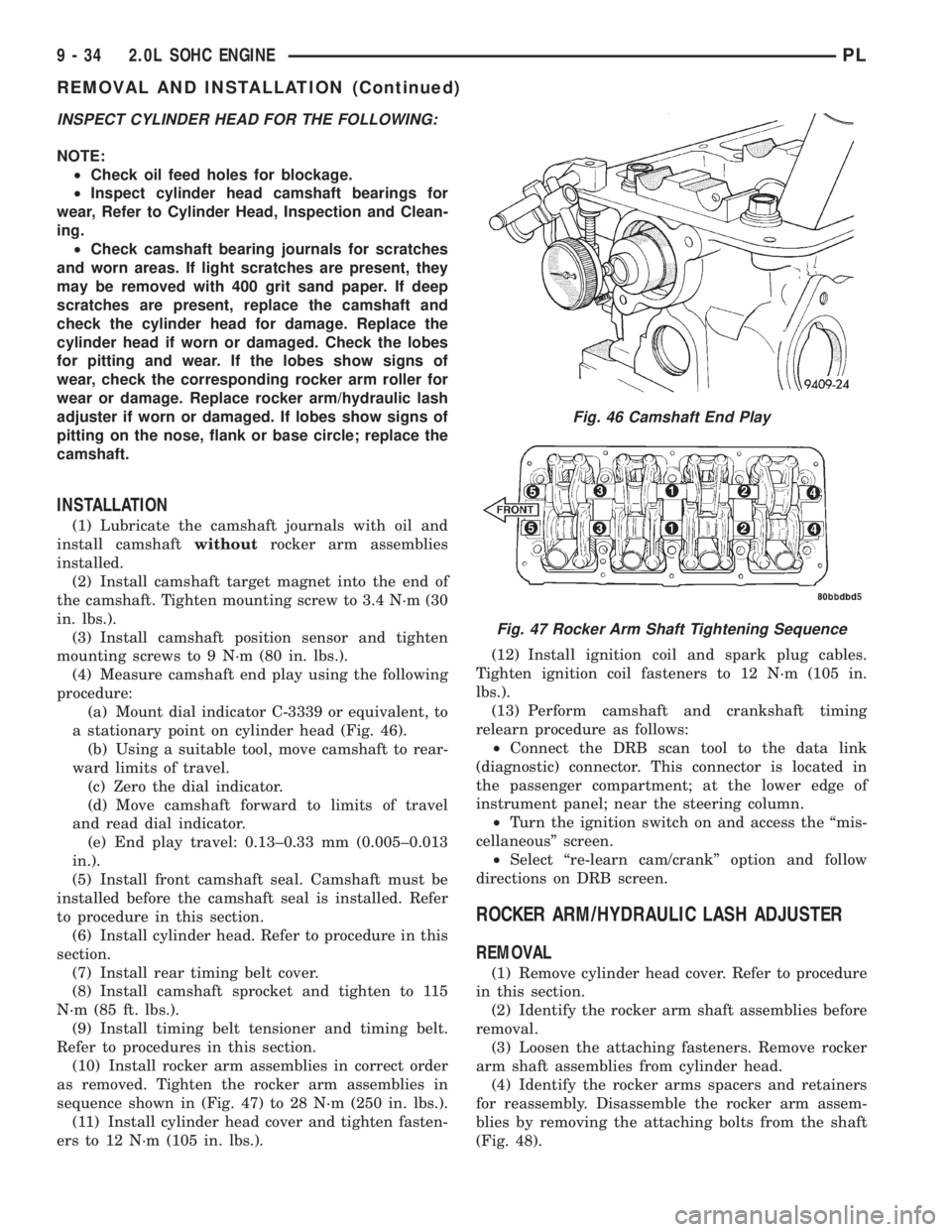
a stationary point on cylinder head (Fig. 46).
(b) Using a suitable tool, move camshaft to rear-
ward limits of travel.
(c) Zero the dial indicator.
(d) Move camshaft forward to limits of travel
and read dial indicator.
(e) End play travel: 0.13±0.33 mm (0.005±0.013
in.).
(5) Install front camshaft seal. Camshaft must be
installed before the camshaft seal is installed. Refer
to procedure in this section.
(6) Install cylinder head. Refer to procedure in this
section.
(7) Install rear timing belt cover.
(8) Install camshaft sprocket and tighten to 115
N´m (85 ft. lbs.).
(9) Install timing belt tensioner and timing belt.
Refer to procedures in this section.
(10) Install rocker arm assemblies in correct order
as removed. Tighten the rocker arm assemblies in
sequence shown in (Fig. 47) to 28 N´m (250 in. lbs.).
(11) Install cylinder head cover and tighten fasten-
ers to 12 N´m (105 in. lbs.).(12) Install ignition coil and spark plug cables.
Tighten ignition coil fasteners to 12 N´m (105 in.
lbs.).
(13) Perform camshaft and crankshaft timing
relearn procedure as follows:
²Connect the DRB scan tool to the data link
(diagnostic) connector. This connector is located in
the passenger compartment; at the lower edge of
instrument panel; near the steering column.
²Turn the ignition switch on and access the ªmis-
cellaneousº screen.
²Select ªre-learn cam/crankº option and follow
directions on DRB screen.
ROCKER ARM/HYDRAULIC LASH ADJUSTER
REMOVAL
(1) Remove cylinder head cover. Refer to procedure
in this section.
(2) Identify the rocker arm shaft assemblies before
removal.
(3) Loosen the attaching fasteners. Remove rocker
arm shaft assemblies from cylinder head.
(4) Identify the rocker arms spacers and retainers
for reassembly. Disassemble the rocker arm assem-
blies by removing the attaching bolts from the shaft
(Fig. 48).
Fig. 46 Camshaft End Play
Fig. 47 Rocker Arm Shaft Tightening Sequence
9 - 34 2.0L SOHC ENGINEPL
REMOVAL AND INSTALLATION (Continued)
Page 763 of 1285

(13) Install ignition coil and spark plug cables.
Connect coil electrical connector.
(14) Install intake manifold. Refer to procedure in
this section.
(15) Install upper radiator hose.
(16) Install ground wire to cylinder head.
(17) Install coolant recovery container.
(18) Connect fuel line to fuel rail.
(19) Install rear timing belt cover, camshaft
sprocket, and timing belt tensioner and timing belt.
Refer to procedures in this section.
(20) Install front timing belt cover.
(21) Install engine mount bracket.
(22) Position engine and install right side engine
mount to engine mount bracket bolt. Tighten bolt to
118 N´m (87 ft. lbs.). Remove jack from beneath
engine.
(23) Install power steering pump assembly.
(24) Install power steering hose support clip and
ground strap to engine mount bracket.
(25) Install upper torque strut.
(26) Raise vehicle.
(27) Install lower torque strut.
(28) Install crankshaft damper.
(29) Install accessory drive belts. Refer to Group 7,
Cooling System Accessory Drive Belt for procedure.
(30) Install right side splash shield and front
wheel.
(31) Install exhaust pipe to exhaust manifold
flange.
(32) Lower vehicle and fill cooling system. Refer to
Group 7, Cooling System for procedure.
(33) Connect negative cable to battery.
(34) Perform camshaft and crankshaft timing
relearn procedure as follows:
²Connect the DRB scan tool to the data link
(diagnostic) connector. This connector is located in
the passenger compartment; at the lower edge of
instrument panel; near the steering column.
²Turn the ignition switch on and access the ªmis-
cellaneousº screen.
²Select ªre-learn cam/crankº option and follow
directions on DRB screen.
CRANKSHAFT DAMPER
REMOVAL
(1) Remove accessory drive belts. Refer to Group 7,
Cooling System for procedure.
(2) Raise vehicle on a hoist and remove right inner
splash shield.
(3) Remove crankshaft damper bolt. Remove
damper using the large side of Special Tool 1026 and
insert 6827-A (Fig. 61).
INSTALLATION
(1) Install crankshaft damper using M12±1.75 x
150 mm bolt, washer, thrust bearing and nut from
Special Tool 6792 (Fig. 62).
Fig. 62 Crankshaft DamperÐInstallation
1 ± M12 Ð 1.753150 MM BOLT, WASHER AND THRUST
BEARING FROM SPECIAL TOOL 6792
Fig. 60 Cylinder Head Tightening Sequence
Fig. 61 Crankshaft DamperÐRemoval
1 ± SPECIAL TOOL 6827±A INSERT
2 ± SPECIAL TOOL 1026 THREE JAW PULLER
9 - 40 2.0L SOHC ENGINEPL
REMOVAL AND INSTALLATION (Continued)
Page 769 of 1285
(10) Install right engine mount to engine mount
bracket through bolt.
(11) Remove jack from under engine.
(12) Install upper torque strut.
(13) Install power steering pump assembly.
(14) Raise vehicle and install lower torque strut.
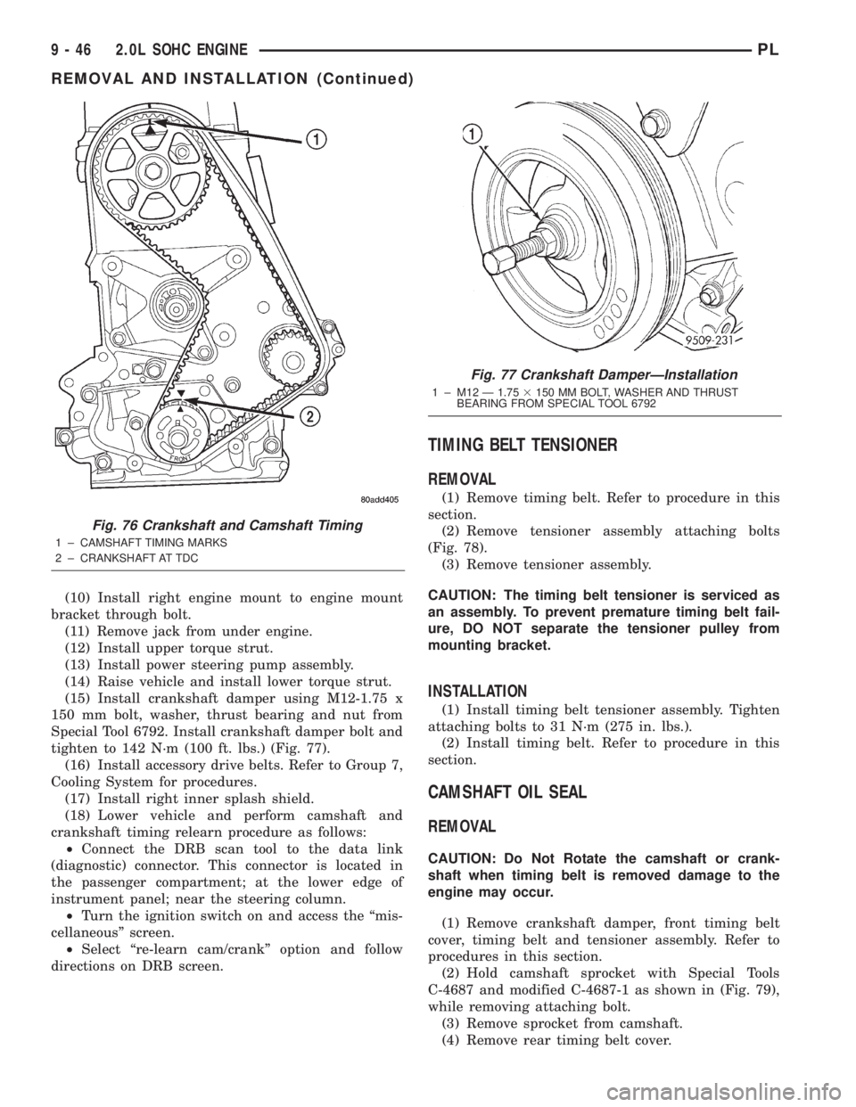
(15) Install crankshaft damper using M12-1.75 x
150 mm bolt, washer, thrust bearing and nut from
Special Tool 6792. Install crankshaft damper bolt and
tighten to 142 N´m (100 ft. lbs.) (Fig. 77).
(16) Install accessory drive belts. Refer to Group 7,
Cooling System for procedures.
(17) Install right inner splash shield.
(18) Lower vehicle and perform camshaft and
crankshaft timing relearn procedure as follows:
²Connect the DRB scan tool to the data link
(diagnostic) connector. This connector is located in
the passenger compartment; at the lower edge of
instrument panel; near the steering column.
²Turn the ignition switch on and access the ªmis-
cellaneousº screen.
²Select ªre-learn cam/crankº option and follow
directions on DRB screen.
TIMING BELT TENSIONER
REMOVAL
(1) Remove timing belt. Refer to procedure in this
section.
(2) Remove tensioner assembly attaching bolts
(Fig. 78).
(3) Remove tensioner assembly.
CAUTION: The timing belt tensioner is serviced as
an assembly. To prevent premature timing belt fail-
ure, DO NOT separate the tensioner pulley from
mounting bracket.
INSTALLATION
(1) Install timing belt tensioner assembly. Tighten
attaching bolts to 31 N´m (275 in. lbs.).
(2) Install timing belt. Refer to procedure in this
section.
CAMSHAFT OIL SEAL
REMOVAL
CAUTION: Do Not Rotate the camshaft or crank-
shaft when timing belt is removed damage to the
engine may occur.
(1) Remove crankshaft damper, front timing belt
cover, timing belt and tensioner assembly. Refer to
procedures in this section.
(2) Hold camshaft sprocket with Special Tools
C-4687 and modified C-4687-1 as shown in (Fig. 79),
while removing attaching bolt.
(3) Remove sprocket from camshaft.
(4) Remove rear timing belt cover.
Fig. 76 Crankshaft and Camshaft Timing
1 ± CAMSHAFT TIMING MARKS
2 ± CRANKSHAFT AT TDC
Fig. 77 Crankshaft DamperÐInstallation
1 ± M12 Ð 1.753150 MM BOLT, WASHER AND THRUST
BEARING FROM SPECIAL TOOL 6792
9 - 46 2.0L SOHC ENGINEPL
REMOVAL AND INSTALLATION (Continued)
Page 778 of 1285
(17) Install rear timing belt cover and camshaft
sprocket.
(18) Install crankshaft sprocket, timing belt ten-
sioner, timing belt, and cover.
(19) Install front engine mount bracket.
(20) Remove engine from repair stand and position
on Special Tools 6135 and 6710 Engine Dolly and
Cradle. Install safety straps around the engine to
cradle and tighten and lock them into position.
(21) Install crankshaft rear oil seal. Refer to proce-
dure in this section.
(22) Install drive plate/flywheel. Apply Mopart
Lock & Seal Adhesive to bolt threads and tighten to
95 N´m (70 ft. lbs.).
(23) Install transaxle to engine.
(24) Install structural collar. Refer to procedure in
this section.
(25) Install engine assembly. Refer to procedure in
this section.
(26) Perform camshaft and crankshaft timing
relearn procedure as follows:
²Connect the DRB scan tool to the data link
(diagnostic) connector. This connector is located in
the passenger compartment; at the lower edge of
instrument panel; near the steering column.
²Turn the ignition switch on and access the ªmis-
cellaneousº screen.
²Select ªre-learn cam/crankº option and follow
directions on DRB screen.
OIL FILTER ADAPTER
REMOVE AND INSTALL
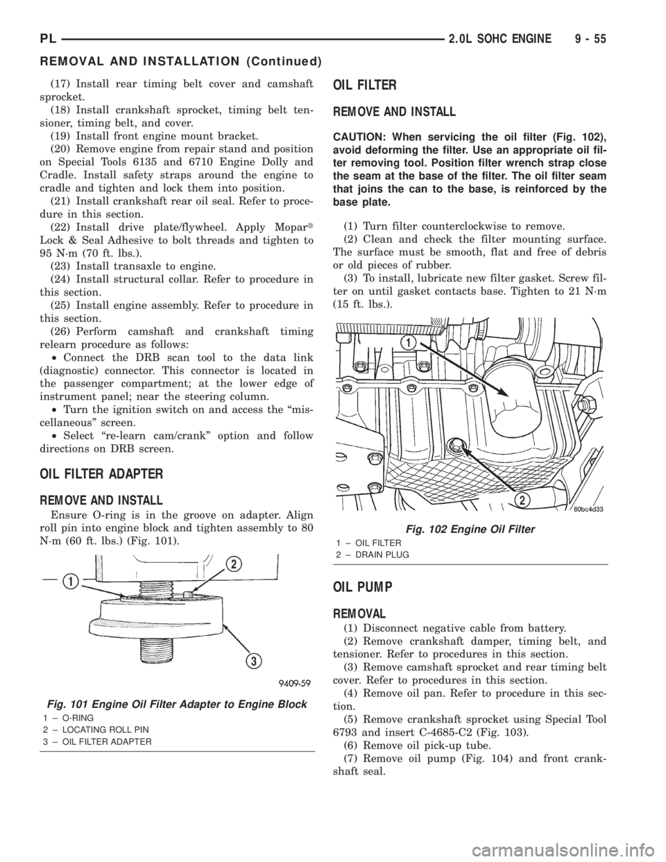
Ensure O-ring is in the groove on adapter. Align
roll pin into engine block and tighten assembly to 80
N´m (60 ft. lbs.) (Fig. 101).
OIL FILTER
REMOVE AND INSTALL
CAUTION: When servicing the oil filter (Fig. 102),
avoid deforming the filter. Use an appropriate oil fil-
ter removing tool. Position filter wrench strap close
the seam at the base of the filter. The oil filter seam
that joins the can to the base, is reinforced by the
base plate.
(1) Turn filter counterclockwise to remove.
(2) Clean and check the filter mounting surface.
The surface must be smooth, flat and free of debris
or old pieces of rubber.
(3) To install, lubricate new filter gasket. Screw fil-
ter on until gasket contacts base. Tighten to 21 N´m
(15 ft. lbs.).
OIL PUMP
REMOVAL
(1) Disconnect negative cable from battery.
(2) Remove crankshaft damper, timing belt, and
tensioner. Refer to procedures in this section.
(3) Remove camshaft sprocket and rear timing belt
cover. Refer to procedures in this section.
(4) Remove oil pan. Refer to procedure in this sec-
tion.
(5) Remove crankshaft sprocket using Special Tool
6793 and insert C-4685-C2 (Fig. 103).
(6) Remove oil pick-up tube.
(7) Remove oil pump (Fig. 104) and front crank-
shaft seal.
Fig. 101 Engine Oil Filter Adapter to Engine Block
1 ± O-RING
2 ± LOCATING ROLL PIN
3 ± OIL FILTER ADAPTER
Fig. 102 Engine Oil Filter
1 ± OIL FILTER
2 ± DRAIN PLUG
PL2.0L SOHC ENGINE 9 - 55
REMOVAL AND INSTALLATION (Continued)