2000 DODGE NEON instrument panel
[x] Cancel search: instrument panelPage 1261 of 1285
INSTALLATION
NOTE: Verify the O-ring condition on the replace-
ment switch.
For installation, reverse the above procedures.
Evacuate and charge the system.
MODE CONTROL CABLE
The Mode Control Cable can be removed and
installed without having to remove the instrument
panel from the vehicle.
REMOVAL
(1) Remove instrument panel center stack bezel
(Fig. 41).
(2) Remove center air duct (Fig. 42).
(3) Remove heater-A/C control head and disconnect
cable (Fig. 43).
(4) Disconnect cable at heater unit.
(5) Remove cable from vehicle.
INSTALLATION
For installation, reverse the above procedures,
adjust cable and test. Refer to Mode Control Cable
Adjustment at the end of this section.
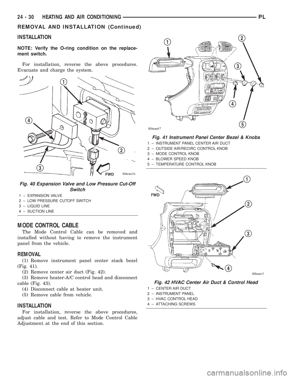
Fig. 40 Expansion Valve and Low Pressure Cut-Off
Switch
1 ± EXPANSION VALVE
2 ± LOW PRESSURE CUTOFF SWITCH
3 ± LIQUID LINE
4 ± SUCTION LINE
Fig. 41 Instrument Panel Center Bezel & Knobs
1 ± INSTRUMENT PANEL CENTER AIR DUCT
2 ± OUTSIDE AIR/RECIRC CONTROL KNOB
3 ± MODE CONTROL KNOB
4 ± BLOWER SPEED KNOB
5 ± TEMPERATURE CONTROL KNOB
Fig. 42 HVAC Center Air Duct & Control Head
1 ± CENTER AIR DUCT
2 ± INSTRUMENT PANEL
3 ± HVAC CONTROL HEAD
4 ± ATTACHING SCREWS
24 - 30 HEATING AND AIR CONDITIONINGPL
REMOVAL AND INSTALLATION (Continued)
Page 1262 of 1285
RECIRCULATION DOOR ACTUATOR
The recirculation door actuator is a vacuum con-
trolled actuator used to control movement of the
recirculation door in air conditioned equipped vehi-
cles.
The instrument panel must be removed from the
vehicle to gain access to the recirculation door actua-
tor.
REMOVAL
(1) Remove instrument panel from vehicle. Refer
to Group 8E, Instrument Panel And Systems for
removal procedures.
(2) Disconnect vacuum line from actuator.
(3) Disconnect actuator from recirculation door
link (Fig. 44).
(4) Release tension on latch, and slide recircula-
tion door actuator off housing.
INSTALLATION
For installation, reverse the above procedures.
SUCTION LINE
WARNING: THE REFRIGERANT MUST BE RECOV-
ERED BEFORE SERVICING ANY PART OF THE
REFRIGERANT SYSTEMS.
REMOVAL
(1) Using a R-134a refrigerant recovery machine,
remove the refrigerant from A/C system.
(2) Remove retaining bolt at expansion valve (Fig.
45).
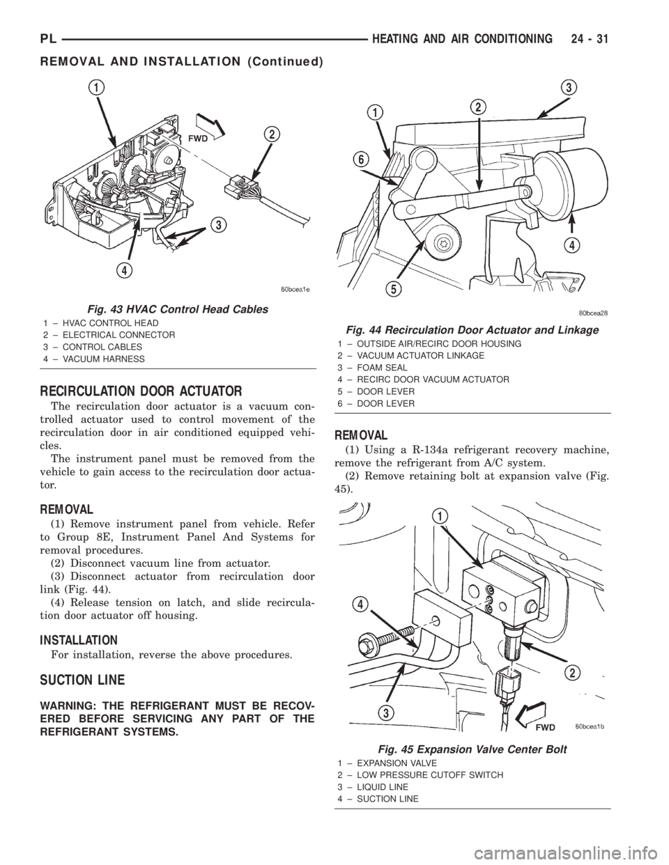
Fig. 43 HVAC Control Head Cables
1 ± HVAC CONTROL HEAD
2 ± ELECTRICAL CONNECTOR
3 ± CONTROL CABLES
4 ± VACUUM HARNESSFig. 44 Recirculation Door Actuator and Linkage
1 ± OUTSIDE AIR/RECIRC DOOR HOUSING
2 ± VACUUM ACTUATOR LINKAGE
3 ± FOAM SEAL
4 ± RECIRC DOOR VACUUM ACTUATOR
5 ± DOOR LEVER
6 ± DOOR LEVER
Fig. 45 Expansion Valve Center Bolt
1 ± EXPANSION VALVE
2 ± LOW PRESSURE CUTOFF SWITCH
3 ± LIQUID LINE
4 ± SUCTION LINE
PLHEATING AND AIR CONDITIONING 24 - 31
REMOVAL AND INSTALLATION (Continued)
Page 1263 of 1285
(3) Remove line at expansion valve.
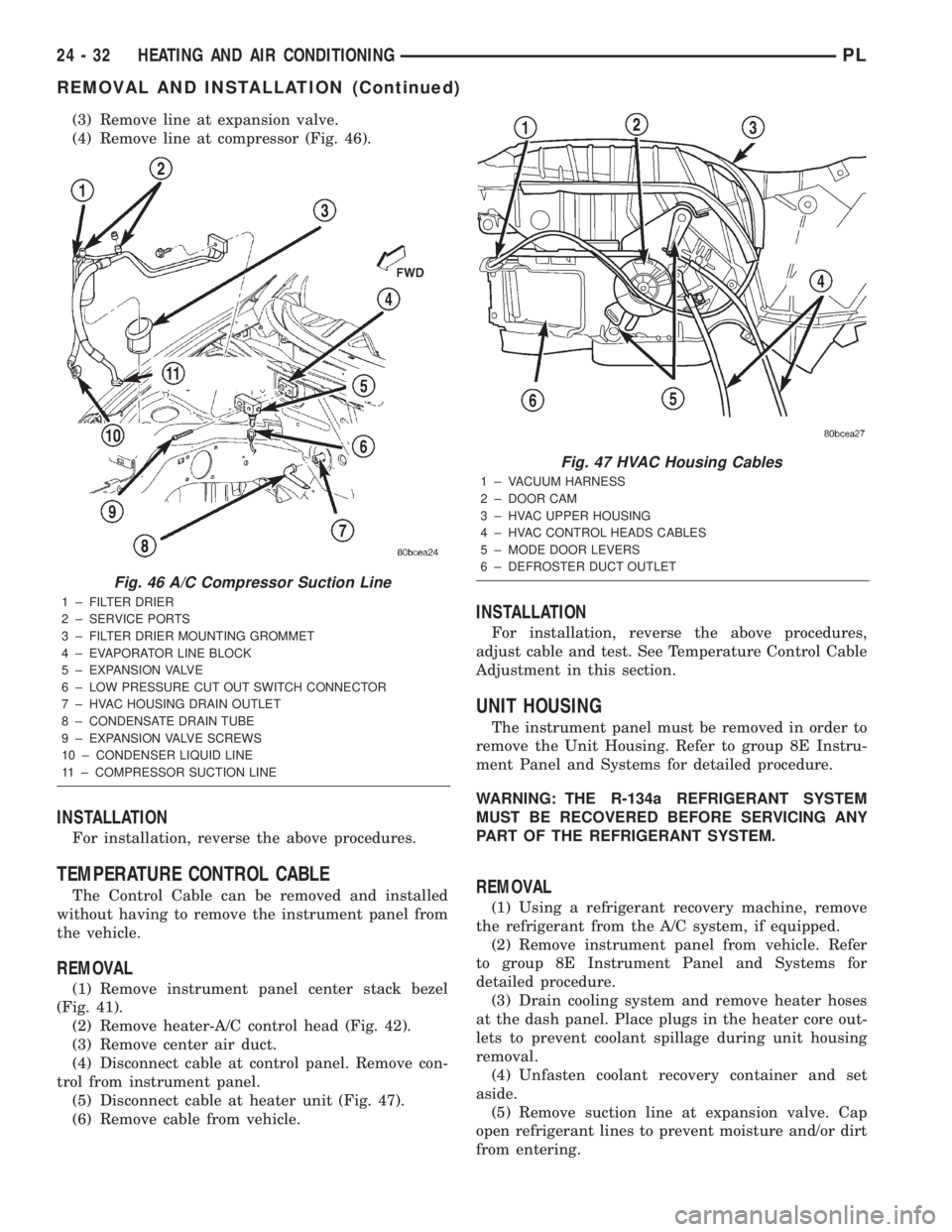
(4) Remove line at compressor (Fig. 46).
INSTALLATION
For installation, reverse the above procedures.
TEMPERATURE CONTROL CABLE
The Control Cable can be removed and installed
without having to remove the instrument panel from
the vehicle.
REMOVAL
(1) Remove instrument panel center stack bezel
(Fig. 41).
(2) Remove heater-A/C control head (Fig. 42).
(3) Remove center air duct.
(4) Disconnect cable at control panel. Remove con-
trol from instrument panel.
(5) Disconnect cable at heater unit (Fig. 47).
(6) Remove cable from vehicle.
INSTALLATION
For installation, reverse the above procedures,
adjust cable and test. See Temperature Control Cable
Adjustment in this section.
UNIT HOUSING
The instrument panel must be removed in order to
remove the Unit Housing. Refer to group 8E Instru-
ment Panel and Systems for detailed procedure.
WARNING: THE R-134a REFRIGERANT SYSTEM
MUST BE RECOVERED BEFORE SERVICING ANY
PART OF THE REFRIGERANT SYSTEM.
REMOVAL
(1) Using a refrigerant recovery machine, remove
the refrigerant from the A/C system, if equipped.
(2) Remove instrument panel from vehicle. Refer
to group 8E Instrument Panel and Systems for
detailed procedure.
(3) Drain cooling system and remove heater hoses
at the dash panel. Place plugs in the heater core out-
lets to prevent coolant spillage during unit housing
removal.
(4) Unfasten coolant recovery container and set
aside.
(5) Remove suction line at expansion valve. Cap
open refrigerant lines to prevent moisture and/or dirt
from entering.
Fig. 46 A/C Compressor Suction Line
1 ± FILTER DRIER
2 ± SERVICE PORTS
3 ± FILTER DRIER MOUNTING GROMMET
4 ± EVAPORATOR LINE BLOCK
5 ± EXPANSION VALVE
6 ± LOW PRESSURE CUT OUT SWITCH CONNECTOR
7 ± HVAC HOUSING DRAIN OUTLET
8 ± CONDENSATE DRAIN TUBE
9 ± EXPANSION VALVE SCREWS
10 ± CONDENSER LIQUID LINE
11 ± COMPRESSOR SUCTION LINE
Fig. 47 HVAC Housing Cables
1 ± VACUUM HARNESS
2 ± DOOR CAM
3 ± HVAC UPPER HOUSING
4 ± HVAC CONTROL HEADS CABLES
5 ± MODE DOOR LEVERS
6 ± DEFROSTER DUCT OUTLET
24 - 32 HEATING AND AIR CONDITIONINGPL
REMOVAL AND INSTALLATION (Continued)
Page 1265 of 1285
INSTALLATION
For installation, reverse the above procedures.
DISASSEMBLY AND ASSEMBLY
HEATER-A/C HOUSING
Use this procedure if any or all of the following
items require service:
²Heater core
²Evaporator
²HVAC housing
The HVAC housing must be removed from the
vehicle before beginning with this procedure. Refer to
Unit Housing in this section for removal procedure.
DISASSEMBLY
(1) Separate the air distribution outlet foam seals
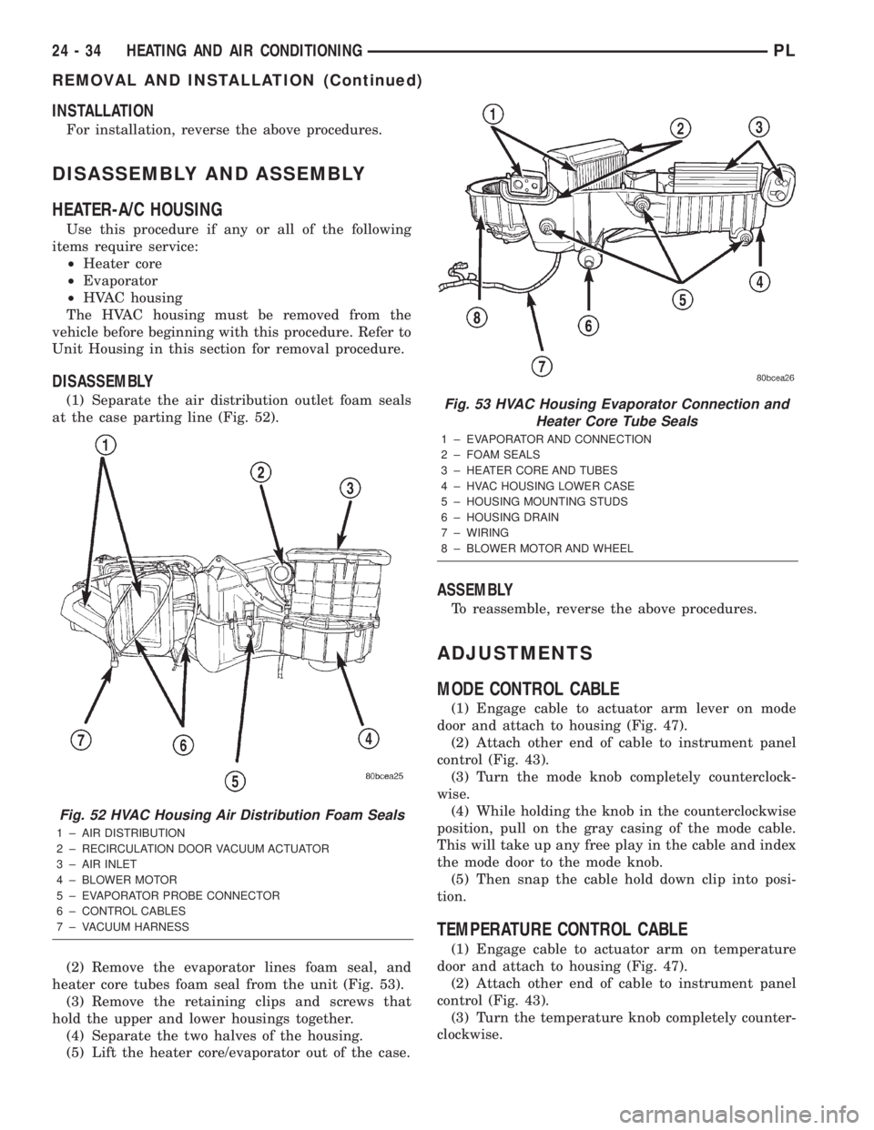
at the case parting line (Fig. 52).
(2) Remove the evaporator lines foam seal, and
heater core tubes foam seal from the unit (Fig. 53).
(3) Remove the retaining clips and screws that
hold the upper and lower housings together.
(4) Separate the two halves of the housing.
(5) Lift the heater core/evaporator out of the case.
ASSEMBLY
To reassemble, reverse the above procedures.
ADJUSTMENTS
MODE CONTROL CABLE
(1) Engage cable to actuator arm lever on mode
door and attach to housing (Fig. 47).
(2) Attach other end of cable to instrument panel
control (Fig. 43).
(3) Turn the mode knob completely counterclock-
wise.
(4) While holding the knob in the counterclockwise
position, pull on the gray casing of the mode cable.
This will take up any free play in the cable and index
the mode door to the mode knob.
(5) Then snap the cable hold down clip into posi-
tion.
TEMPERATURE CONTROL CABLE
(1) Engage cable to actuator arm on temperature
door and attach to housing (Fig. 47).
(2) Attach other end of cable to instrument panel
control (Fig. 43).
(3) Turn the temperature knob completely counter-
clockwise.
Fig. 52 HVAC Housing Air Distribution Foam Seals
1 ± AIR DISTRIBUTION
2 ± RECIRCULATION DOOR VACUUM ACTUATOR
3 ± AIR INLET
4 ± BLOWER MOTOR
5 ± EVAPORATOR PROBE CONNECTOR
6 ± CONTROL CABLES
7 ± VACUUM HARNESS
Fig. 53 HVAC Housing Evaporator Connection and
Heater Core Tube Seals
1 ± EVAPORATOR AND CONNECTION
2 ± FOAM SEALS
3 ± HEATER CORE AND TUBES
4 ± HVAC HOUSING LOWER CASE
5 ± HOUSING MOUNTING STUDS
6 ± HOUSING DRAIN
7 ± WIRING
8 ± BLOWER MOTOR AND WHEEL
24 - 34 HEATING AND AIR CONDITIONINGPL
REMOVAL AND INSTALLATION (Continued)
Page 1268 of 1285
HEATING AND AIR CONDITIONING
TABLE OF CONTENTS
page page
REMOVAL AND INSTALLATION
EVAPORATOR CORE ± R. H. D...............1
HEATER CORE ± R. H. D....................3SPECIFICATIONS
TORQUE SPECIFICATIONS..................6
REMOVAL AND INSTALLATION
EVAPORATOR CORE ± R. H. D.
REMOVAL
WARNING: ON VEHICLES EQUIPPED WITH AIR-
BAGS, REFER TO GROUP 8M ± PASSIVE
RESTRAINT SYSTEMS BEFORE ATTEMPTING ANY
STEERING WHEEL, STEERING COLUMN, OR
INSTRUMENT PANEL COMPONENT DIAGNOSIS OR
SERVICE. FAILURE TO TAKE THE PROPER PRE-
CAUTIONS COULD RESULT IN ACCIDENTAL AIR-
BAG DEPLOYMENT AND POSSIBLE PERSONAL
INJURY.
WARNING: DO NOT OPEN THE RADIATOR DRAIN-
COCK OR DISCONNECT COOLANT HOSES WHEN
THE COOLING SYSTEM IS HOT AND UNDER PRES-
SURE. SERIOUS BURNS FROM COOLANT CAN
OCCUR.
WARNING: READ ALL SAFETY PRECAUTIONS AND
WARNINGS BEFORE PROCEEDING WITH THIS
OPERATION.
(1) Disconnect the negative battery cable.
(2) Drain the cooling system. Refer to Group 7,
Cooling System for the procedure.
(3) Evacuate the refrigerant system.
(4) Remove the instrument panel. Refer to Group
8E, Instrument Panel and Systems for the procedure.
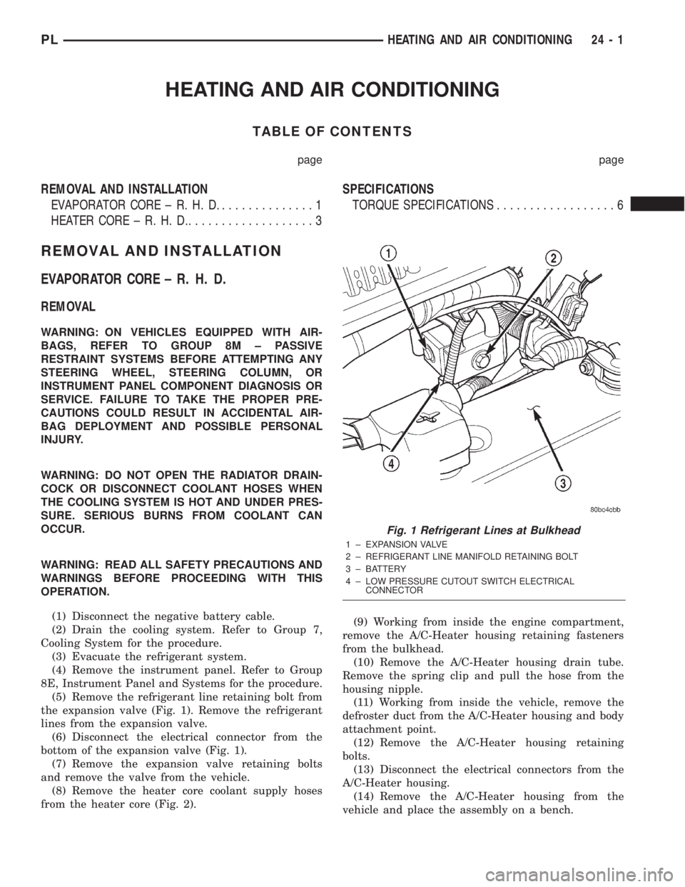
(5) Remove the refrigerant line retaining bolt from
the expansion valve (Fig. 1). Remove the refrigerant
lines from the expansion valve.
(6) Disconnect the electrical connector from the
bottom of the expansion valve (Fig. 1).
(7) Remove the expansion valve retaining bolts
and remove the valve from the vehicle.
(8) Remove the heater core coolant supply hoses
from the heater core (Fig. 2).(9) Working from inside the engine compartment,
remove the A/C-Heater housing retaining fasteners
from the bulkhead.
(10) Remove the A/C-Heater housing drain tube.
Remove the spring clip and pull the hose from the
housing nipple.
(11) Working from inside the vehicle, remove the
defroster duct from the A/C-Heater housing and body
attachment point.
(12) Remove the A/C-Heater housing retaining
bolts.
(13) Disconnect the electrical connectors from the
A/C-Heater housing.
(14) Remove the A/C-Heater housing from the
vehicle and place the assembly on a bench.
Fig. 1 Refrigerant Lines at Bulkhead
1 ± EXPANSION VALVE
2 ± REFRIGERANT LINE MANIFOLD RETAINING BOLT
3 ± BATTERY
4 ± LOW PRESSURE CUTOUT SWITCH ELECTRICAL
CONNECTOR
PLHEATING AND AIR CONDITIONING 24 - 1
Page 1270 of 1285
(7) Install the A/C-Heater housing retaining fas-
teners. Torque the fasteners to 20 N´m (177 in. lbs.).
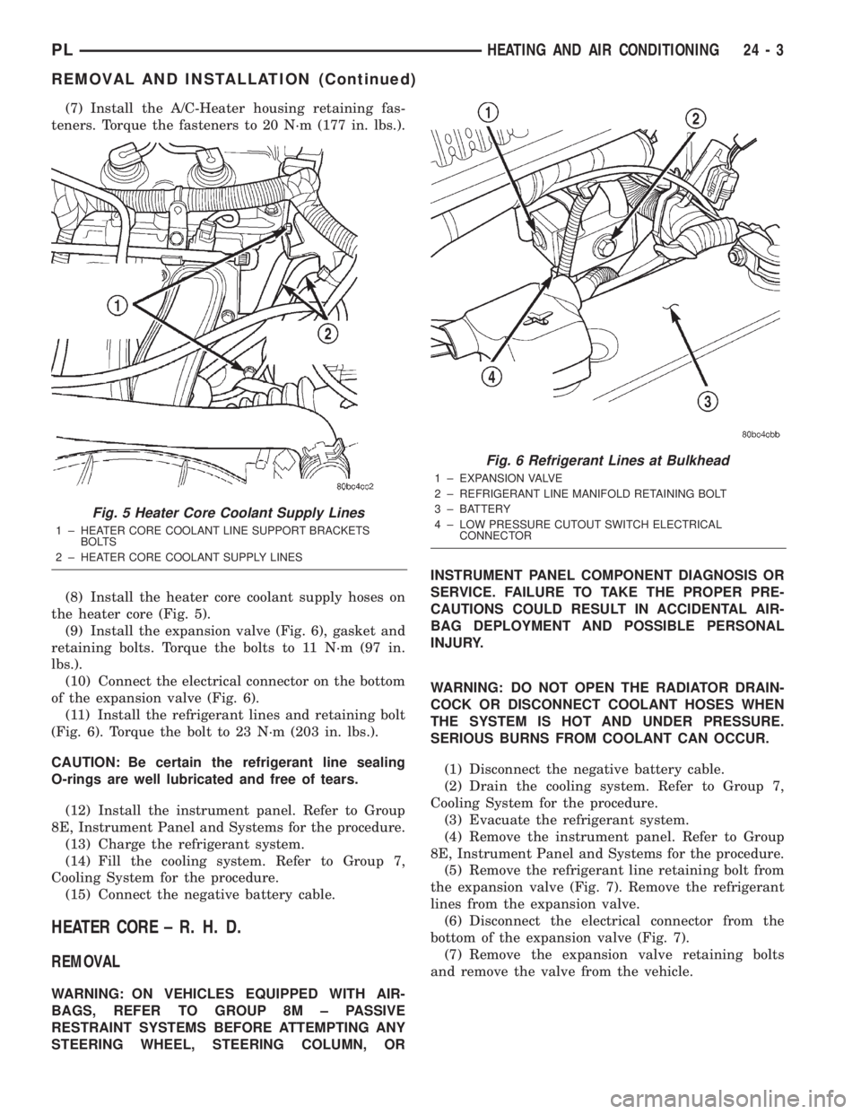
(8) Install the heater core coolant supply hoses on
the heater core (Fig. 5).
(9) Install the expansion valve (Fig. 6), gasket and
retaining bolts. Torque the bolts to 11 N´m (97 in.
lbs.).
(10) Connect the electrical connector on the bottom
of the expansion valve (Fig. 6).
(11) Install the refrigerant lines and retaining bolt
(Fig. 6). Torque the bolt to 23 N´m (203 in. lbs.).
CAUTION: Be certain the refrigerant line sealing
O-rings are well lubricated and free of tears.
(12) Install the instrument panel. Refer to Group
8E, Instrument Panel and Systems for the procedure.
(13) Charge the refrigerant system.
(14) Fill the cooling system. Refer to Group 7,
Cooling System for the procedure.
(15) Connect the negative battery cable.
HEATER CORE ± R. H. D.
REMOVAL
WARNING: ON VEHICLES EQUIPPED WITH AIR-
BAGS, REFER TO GROUP 8M ± PASSIVE
RESTRAINT SYSTEMS BEFORE ATTEMPTING ANY
STEERING WHEEL, STEERING COLUMN, ORINSTRUMENT PANEL COMPONENT DIAGNOSIS OR
SERVICE. FAILURE TO TAKE THE PROPER PRE-
CAUTIONS COULD RESULT IN ACCIDENTAL AIR-
BAG DEPLOYMENT AND POSSIBLE PERSONAL
INJURY.
WARNING: DO NOT OPEN THE RADIATOR DRAIN-
COCK OR DISCONNECT COOLANT HOSES WHEN
THE SYSTEM IS HOT AND UNDER PRESSURE.
SERIOUS BURNS FROM COOLANT CAN OCCUR.
(1) Disconnect the negative battery cable.
(2) Drain the cooling system. Refer to Group 7,
Cooling System for the procedure.
(3) Evacuate the refrigerant system.
(4) Remove the instrument panel. Refer to Group
8E, Instrument Panel and Systems for the procedure.
(5) Remove the refrigerant line retaining bolt from
the expansion valve (Fig. 7). Remove the refrigerant
lines from the expansion valve.
(6) Disconnect the electrical connector from the
bottom of the expansion valve (Fig. 7).
(7) Remove the expansion valve retaining bolts
and remove the valve from the vehicle.
Fig. 5 Heater Core Coolant Supply Lines
1 ± HEATER CORE COOLANT LINE SUPPORT BRACKETS
BOLTS
2 ± HEATER CORE COOLANT SUPPLY LINES
Fig. 6 Refrigerant Lines at Bulkhead
1 ± EXPANSION VALVE
2 ± REFRIGERANT LINE MANIFOLD RETAINING BOLT
3 ± BATTERY
4 ± LOW PRESSURE CUTOUT SWITCH ELECTRICAL
CONNECTOR
PLHEATING AND AIR CONDITIONING 24 - 3
REMOVAL AND INSTALLATION (Continued)
Page 1273 of 1285
(12) Install the instrument panel. Refer to Group
8E, Instrument Panel and Systems for the procedure.
(13) Charge the refrigerant system.
(14) Fill the cooling system. Refer to Group 7,
Cooling System for the procedure.
(15) Connect the negative battery cable.SPECIFICATIONS
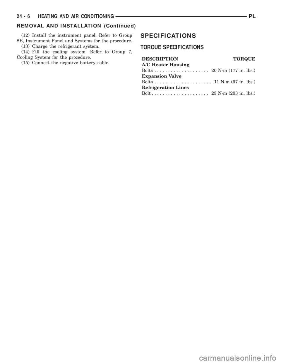
TORQUE SPECIFICATIONS
DESCRIPTION TORQUE
A/C Heater Housing
Bolts.................... 20N´m(177 in. lbs.)
Expansion Valve
Bolts..................... 11N´m(97in.lbs.)
Refrigeration Lines
Bolt..................... 23N´m(203 in. lbs.)
24 - 6 HEATING AND AIR CONDITIONINGPL
REMOVAL AND INSTALLATION (Continued)
Page 1274 of 1285
INTRODUCTION
TABLE OF CONTENTS
page page
DESCRIPTION AND OPERATION
VEHICLE IDENTIFICATION NUMBER..........1
VEHICLE SAFETY CERTIFICATION LABEL......2
BODY CODE EMBOSS.....................2
SERVICE PROCEDURES
THREADED HOLE REPAIR..................2SPECIFICATIONS
INTERNATIONAL VEHICLE CONTROL AND
DISPLAY SYMBOLS.....................2
FASTENER IDENTIFICATION.................3
FASTENER USAGE........................6
METRIC SYSTEM.........................6
DESCRIPTION AND OPERATION
VEHICLE IDENTIFICATION NUMBER
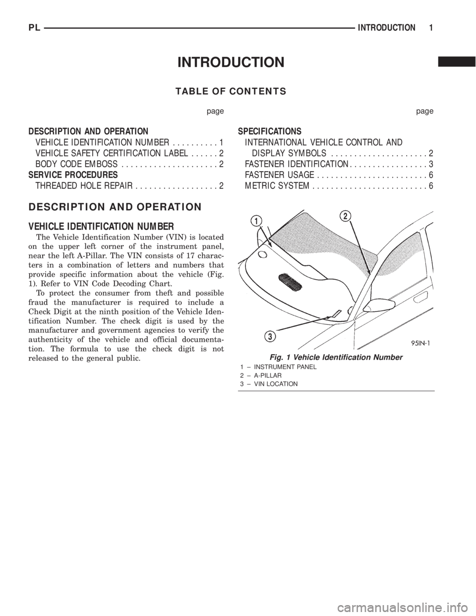
The Vehicle Identification Number (VIN) is located
on the upper left corner of the instrument panel,
near the left A-Pillar. The VIN consists of 17 charac-
ters in a combination of letters and numbers that
provide specific information about the vehicle (Fig.
1). Refer to VIN Code Decoding Chart.
To protect the consumer from theft and possible
fraud the manufacturer is required to include a
Check Digit at the ninth position of the Vehicle Iden-
tification Number. The check digit is used by the
manufacturer and government agencies to verify the
authenticity of the vehicle and official documenta-
tion. The formula to use the check digit is not
released to the general public.
Fig. 1 Vehicle Identification Number
1 ± INSTRUMENT PANEL
2 ± A-PILLAR
3 ± VIN LOCATION
PLINTRODUCTION 1