2000 DODGE NEON belt
[x] Cancel search: beltPage 1236 of 1285
A/C SERVICE PORT VALVE CORES
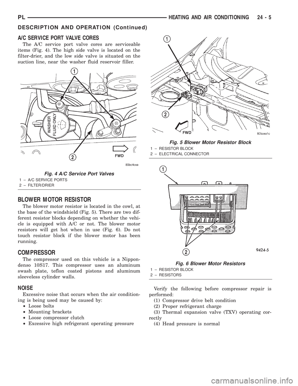
The A/C service port valve cores are serviceable
items (Fig. 4). The high side valve is located on the
filter-drier, and the low side valve is situated on the
suction line, near the washer fluid reservoir filler.
BLOWER MOTOR RESISTOR
The blower motor resistor is located in the cowl, at
the base of the windshield (Fig. 5). There are two dif-
ferent resistor blocks depending on whether the vehi-
cle is equipped with A/C or not. The blower motor
resistors will get hot when in use (Fig. 6). Do not
touch resistor block if the blower motor has been
running.
COMPRESSOR
The compressor used on this vehicle is a Nippon-
denso 10S17. This compressor uses an aluminum
swash plate, teflon coated pistons and aluminum
sleeveless cylinder walls.
NOISE
Excessive noise that occurs when the air condition-
ing is being used may be caused by:
²Loose bolts
²Mounting brackets
²Loose compressor clutch
²Excessive high refrigerant operating pressureVerify the following before compressor repair is
performed:
(1) Compressor drive belt condition
(2) Proper refrigerant charge
(3) Thermal expansion valve (TXV) operating cor-
rectly
(4) Head pressure is normal
Fig. 4 A/C Service Port Valves
1 ± A/C SERVICE PORTS
2 ± FILTER/DRIER
Fig. 5 Blower Motor Resistor Block
1 ± RESISTOR BLOCK
2 ± ELECTRICAL CONNECTOR
Fig. 6 Blower Motor Resistors
1 ± RESISTOR BLOCK
2 ± RESISTORS
PLHEATING AND AIR CONDITIONING 24 - 5
DESCRIPTION AND OPERATION (Continued)
Page 1242 of 1285
BLOWER MOTOR VIBRATION AND/OR NOISE
DIAGNOSIS
The resistor block supplies the blower motor with
varied voltage (low and middle speeds) or battery
voltage (high speed).
CAUTION: Stay clear of the blower motor and resis-
tor block (Hot). Do not operate the blower motor
with the resistor block removed from the heater-A/C
housing.
Refer to the Blower Motor Vibration/Noise chart
for diagnosis.
COMPRESSOR NOISE DIAGNOSIS
Excessive noise while the A/C is being used, can be
caused by loose mounts, loose clutch, or high operat-
ing pressure. Verify compressor drive belt condition,
proper refrigerant charge and head pressure before
compressor repair is performed.
If the A/C drive belt slips at initial start-up, it does
not necessarily mean the compressor has failed.
With the close tolerances of a compressor it is pos-
sible to experience a temporary lockup. The longer
the A/C system is inactive, the more likely the condi-
tion to occur.
This condition is the result of normal refrigerant
movement within the A/C system caused by temper-
ature changes. The refrigerant movement may wash
the oil out of the compressor.
EVAPORATOR PROBE TEST
The work area and vehicle must be between 16É C
(60É F) and 32É C (90É F) when testing the switch.
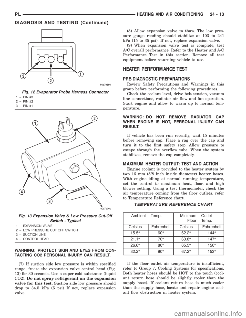
(1) Disconnect the three wire connector from the
evaporator probe lead located behind the glove box
(Fig. 12).
(2) Start engine and set A/C to low blower motor
speed, panel, full cool, and RECIRC.
(3) Using a voltmeter, check for battery voltage
between Pin 1 and 2. If no voltage is detected, there
is no power to the switch. Check wiring and fuses.
Refer to Group 8W, Wiring Diagrams for circuit diag-
nosis.
(4) Using a voltmeter, check for battery voltage
between Pin 1 and Pin 3. If no voltage is detected,
there is no voltage from the Powertrain Control Mod-
ule. Refer to Group 8W, Wiring Diagrams. If voltage
is OK, connect a jumper wire between Pin 1 and Pin
3. The compressor clutch should engage. If the clutch
engages, remove the jumper wire immediately and go
to Step 5. If the compressor clutch does not engage,
check the operation of the clutch and repair as nec-
essary.(5) If compressor clutch engages, connect the evap-
orator probe 3-way connector. The compressor clutch
should engage or cycle depending on evaporator tem-
perature. If OK, go to Step 6. If not OK, replace the
clutch cycling switch.
(6) The engine running and the A/C set to:
²Blower motor on low speed
²Panel position
²Full cool
²RECIRC.
Close all doors and windows. Place a thermometer in
the center discharge vent.
(7) If the clutch does not begin to cycle off between
2É C to 7É C (35É F to 45É F), verify that the evapo-
rator probe is fully installed and not loose in evapo-
rator. If it is not properly installed, install probe and
retest outlet temperature. If the evaporator probe is
properly installed, replace the clutch cycling switch.
EXPANSION VALVE
NOTE: Expansion valve tests should be performed
after compressor tests.
Liquid CO2 is required to test the expansion
valve. It is available from most welding supply facil-
ities. CO2 is also available from companies which
service and sell fire extinguishers.
Review Safety Precautions and Warnings in the
General Information section of this Group. The work
area and vehicle must be 21É to 27ÉC (70É to 85ÉF)
when testing expansion valve. To test the expansion
valve:
(1) Connect a charging station or manifold gauge
set to the refrigerant system service ports.
(2) Disconnect wire connector at low pressure cut-
off switch (Fig. 13). Using a jumper wire, jump ter-
minals inside wire connector boot.
(3) Close all doors, windows and vents to the pas-
senger compartment.
(4) Set Heater-A/C control to A/C, full heat, floor,
RECIRC. and high blower.
(5) Start the engine and hold the idle speed (1000
rpm). After the engine has reached running temper-
ature, allow the passenger compartment to heat up.
This will create the need for maximum refrigerant
flow into the evaporator.
(6) If the refrigerant charge is sufficient, discharge
(high pressure) gauge should read 965 to 2620 kPa
(140 to 380 psi). Suction (low pressure) gauge should
read 103 to 2417 kPa (15 to 35 psi). If system cannot
achieve proper pressure readings, replace the expan-
sion valve. If pressure is correct, proceed with test.
PLHEATING AND AIR CONDITIONING 24 - 11
DIAGNOSIS AND TESTING (Continued)
Page 1244 of 1285
WARNING: PROTECT SKIN AND EYES FROM CON-
TACTING CO2 PERSONAL INJURY CAN RESULT.
(7) If suction side low pressure is within specified
range, freeze the expansion valve control head (Fig.
13) for 30 seconds. Use a super cold substance (liquid
CO2).Do not spray refrigerant on the expansion
valve for this test.Suction side low pressure should
drop to 34.5 kPa (5 psi) If not, replace expansion
valve.(8) Allow expansion valve to thaw. The low pres-
sure gauge reading should stabilize at 103 to 241
kPa (15 to 35 psi). If not, replace expansion valve.
(9) When expansion valve test is complete, test
A/C overall performance. Refer to the Heater and A/C
Performance Test in this section. Remove all test
equipment before returning vehicle to use.
HEATER PERFORMANCE TEST
PRE-DIAGNOSTIC PREPARATIONS
Review Safety Precautions and Warnings in this
group before performing the following procedures.
Check the coolant level, drive belt tension, vacuum
line connections, radiator air flow and fan operation.
Start engine and allow to warm up to normal tem-
perature.
WARNING: DO NOT REMOVE RADIATOR CAP
WHEN ENGINE IS HOT, PERSONAL INJURY CAN
RESULT.
If vehicle has been run recently, wait 15 minutes
before removing cap. Place a rag over the cap and
turn it to the first safety stop. Allow pressure to
escape through the overflow tube. When the system
stabilizes, remove the cap completely.
MAXIMUM HEATER OUTPUT: TEST AND ACTION
Engine coolant is provided to the heater system by
two 16 mm (5/8 inch inside diameter) heater hoses.
With engine idling at normal running temperature,
set the control to maximum heat, floor, and high
blower setting. Using a test thermometer, check the
air temperature coming from the floor outlets, refer
to Temperature Reference chart.
If the floor outlet air temperature is insufficient,
refer to Group 7, Cooling Systems for specifications.
Both heater hoses should be HOT to the touch (cool-
ant return hose should be slightly cooler than the
supply hose). If coolant return hose is much cooler
than the supply hose, locate and repair engine cool-
ant flow obstruction in heater system.
Fig. 12 Evaporator Probe Harness Connector
1 ± PIN #3
2 ± PIN #2
3 ± PIN #1
Fig. 13 Expansion Valve & Low Pressure Cut-Off
Switch - Typical
1 ± EXPANSION VALVE
2 ± LOW PRESSURE CUT OFF SWITCH
3 ± SUCTION LINE
4 ± CONTROL HEAD
TEMPERATURE REFERENCE CHART
Ambient Temp. Minimum
FloorOutlet
Temp.
Celsius Fahrenheit Celsius Fahrenheit
15.5É 60É 62.2É 144É
21.1É 70É 63.8É 147É
26.6É 80É 65.5É 150É
32.2É 90É 67.2É 153É
PLHEATING AND AIR CONDITIONING 24 - 13
DIAGNOSIS AND TESTING (Continued)
Page 1253 of 1285
BLOWER MOTOR RESISTOR
CAUTION: Stay clear of the blower motor and resis-
tor block (Hot). Do not operate the blower motor
with the resistor block removed.
REMOVAL
(1) Remove windshield wipers.
(2) Remove cowl top screen.
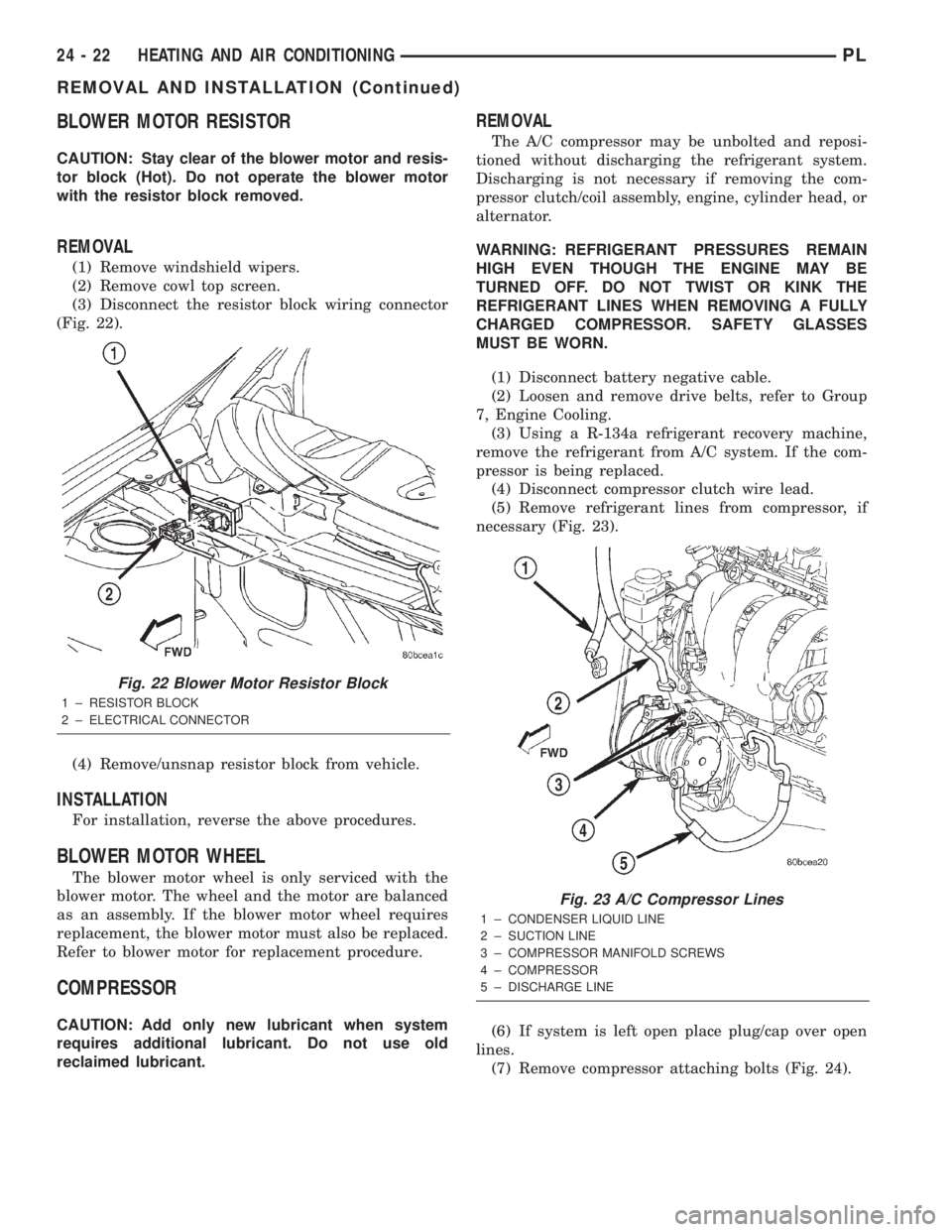
(3) Disconnect the resistor block wiring connector
(Fig. 22).
(4) Remove/unsnap resistor block from vehicle.
INSTALLATION
For installation, reverse the above procedures.
BLOWER MOTOR WHEEL
The blower motor wheel is only serviced with the
blower motor. The wheel and the motor are balanced
as an assembly. If the blower motor wheel requires
replacement, the blower motor must also be replaced.
Refer to blower motor for replacement procedure.
COMPRESSOR
CAUTION: Add only new lubricant when system
requires additional lubricant. Do not use old
reclaimed lubricant.
REMOVAL
The A/C compressor may be unbolted and reposi-
tioned without discharging the refrigerant system.
Discharging is not necessary if removing the com-
pressor clutch/coil assembly, engine, cylinder head, or
alternator.
WARNING: REFRIGERANT PRESSURES REMAIN
HIGH EVEN THOUGH THE ENGINE MAY BE
TURNED OFF. DO NOT TWIST OR KINK THE
REFRIGERANT LINES WHEN REMOVING A FULLY
CHARGED COMPRESSOR. SAFETY GLASSES
MUST BE WORN.
(1) Disconnect battery negative cable.
(2) Loosen and remove drive belts, refer to Group
7, Engine Cooling.
(3) Using a R-134a refrigerant recovery machine,
remove the refrigerant from A/C system. If the com-
pressor is being replaced.
(4) Disconnect compressor clutch wire lead.
(5) Remove refrigerant lines from compressor, if
necessary (Fig. 23).
(6) If system is left open place plug/cap over open
lines.
(7) Remove compressor attaching bolts (Fig. 24).
Fig. 22 Blower Motor Resistor Block
1 ± RESISTOR BLOCK
2 ± ELECTRICAL CONNECTOR
Fig. 23 A/C Compressor Lines
1 ± CONDENSER LIQUID LINE
2 ± SUCTION LINE
3 ± COMPRESSOR MANIFOLD SCREWS
4 ± COMPRESSOR
5 ± DISCHARGE LINE
24 - 22 HEATING AND AIR CONDITIONINGPL
REMOVAL AND INSTALLATION (Continued)