2000 DODGE NEON belt
[x] Cancel search: beltPage 1160 of 1285
(1) Position door latch on vehicle and install
screws attaching latch to door end frame.
(2) Connect linkage rods to latch.
(3) Connect lock and latch rods to door latch.
(4) Tighten lower rear run channel.
(5) Install door trim panel.
REAR DOOR LATCH STRIKER
REMOVAL
(1) Mark outline of door latch striker on B-pillar to
aid installation.
(2) Remove screws attaching door latch striker to
B-pillar (Fig. 47).
(3) Remove door latch striker from vehicle.
INSTALLATION
(1) Install door latch striker from vehicle.
(2) Install screws attaching door latch striker to
B-pillar.
(3) Align marked outline of door latch striker on
B-pillar to aid installation.
REAR DOOR GLASS
REMOVAL
(1) Remove door trim panel and inner belt weath-
erstrip.
(2) Lower the window to 50 mm (2 ins.) from bot-
tom of travel.
(3) Loosen bolts attaching rear lower run channel
to inner door panel (Fig. 47).
(4) Remove rear run channel from door.
(5) Loosen screws attaching window regulator
channel to glass.
(6) Slide channel rearward to allow screw heads to
pass through key hole slots in channel.
(7) Remove glass from roller channel.
(8) Lift door glass upward out of the opening at
the top of door.
INSTALLATION
(1) Lower door glass through opening in top of
door and into position in the window regulator.
(2) Position door glass onto roller channel.
(3) Slide roller channel forward to allow screw
heads to engage key hole slots in channel.
(4) Tighten screws attaching window regulator
roller channel to glass.
(5) Install inner door belt door trim panel inner
belt weatherstrip.
(6) Operate window and check for interference.
Adjust glass as necessary.
REAR DOOR WINDOW REGULATOR
REMOVAL
(1) Remove door trim panel.
(2) Remove door glass from regulator channel.
(3) Loosen screws attaching window regulator
channel and crank housing to door panel (Fig. 47).
(4) Disengage screw and bolt heads from keyhole
slots in door panel.
(5) Loosen bolts attaching window regulator to
door panel.
(6) Disengage regulator from door panel, and
crank housing.
(7) Slide regulator rearward and rotate forward
end of roller channel through access hole in door
panel,
(8) Remove window regulator from door through
access hole in inner panel.
INSTALLATION
(1) position window regulator and crank housing
on door panel through access hole in door panel.
(2) Tighten bolts attaching window regulator to
door panel.
(3) Engage window regulator bolt heads on chan-
nel to key hole slots in door panel.
(4) Tighten screw attaching window regulator
channel and crank housing.
(5) Position glass to regulator roller channel.
(6) Tighten fasteners attaching door glass to roller
channel.
(7) Install door trim panel.
REAR DOOR GLASS RUN WEATHERSTRIP
REMOVAL
(1) Remove door trim panel, water dam as neces-
sary.
(2) Remove door glass.
(3) Remove weatherstrip fasteners.
(4) Pull weatherstrip from lower front channel
above door latch.
(5) Pull run weatherstrip from window frame
channel (Fig. 48).
INSTALLATION
(1) Clean butyl material from door flange area.
(2) Place door run weatherstrip in position on win-
dow frame channel.
(3) Push door run weatherstrip into window frame
channel.
(4) Push weatherstrip into lower front channel
above door latch.
(5) Install weatherstrip fasteners.
(6) Install door glass.
PLBODY 23 - 43
REMOVAL AND INSTALLATION (Continued)
Page 1169 of 1285
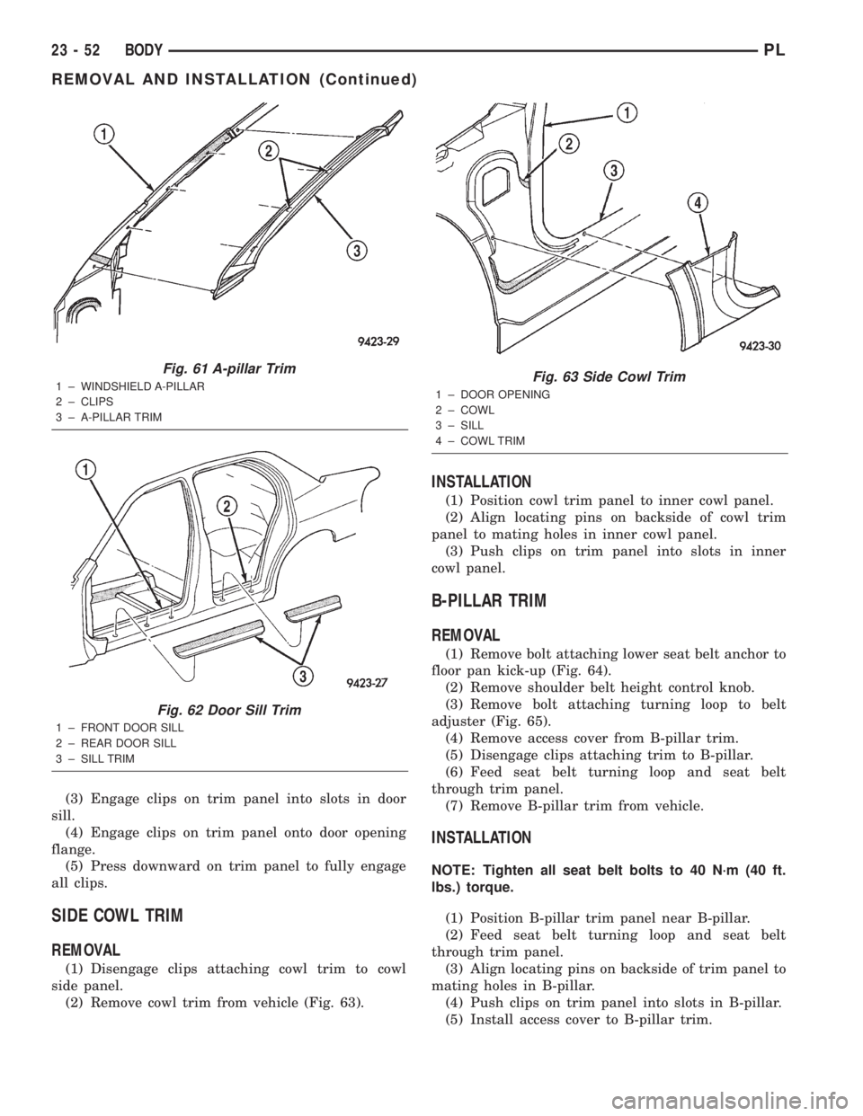
(3) Engage clips on trim panel into slots in door
sill.
(4) Engage clips on trim panel onto door opening
flange.
(5) Press downward on trim panel to fully engage
all clips.
SIDE COWL TRIM
REMOVAL
(1) Disengage clips attaching cowl trim to cowl
side panel.
(2) Remove cowl trim from vehicle (Fig. 63).
INSTALLATION
(1) Position cowl trim panel to inner cowl panel.
(2) Align locating pins on backside of cowl trim
panel to mating holes in inner cowl panel.
(3) Push clips on trim panel into slots in inner
cowl panel.
B-PILLAR TRIM
REMOVAL
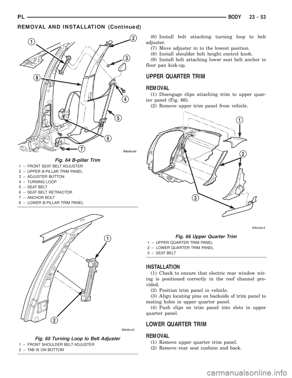
(1) Remove bolt attaching lower seat belt anchor to
floor pan kick-up (Fig. 64).
(2) Remove shoulder belt height control knob.
(3) Remove bolt attaching turning loop to belt
adjuster (Fig. 65).
(4) Remove access cover from B-pillar trim.
(5) Disengage clips attaching trim to B-pillar.
(6) Feed seat belt turning loop and seat belt
through trim panel.
(7) Remove B-pillar trim from vehicle.
INSTALLATION
NOTE: Tighten all seat belt bolts to 40 N´m (40 ft.
lbs.) torque.
(1) Position B-pillar trim panel near B-pillar.
(2) Feed seat belt turning loop and seat belt
through trim panel.
(3) Align locating pins on backside of trim panel to
mating holes in B-pillar.
(4) Push clips on trim panel into slots in B-pillar.
(5) Install access cover to B-pillar trim.
Fig. 61 A-pillar Trim
1 ± WINDSHIELD A-PILLAR
2 ± CLIPS
3 ± A-PILLAR TRIM
Fig. 62 Door Sill Trim
1 ± FRONT DOOR SILL
2 ± REAR DOOR SILL
3 ± SILL TRIM
Fig. 63 Side Cowl Trim
1 ± DOOR OPENING
2 ± COWL
3 ± SILL
4 ± COWL TRIM
23 - 52 BODYPL
REMOVAL AND INSTALLATION (Continued)
Page 1170 of 1285
(6) Install bolt attaching turning loop to belt
adjuster.
(7) Move adjuster in to the lowest position.
(8) Install shoulder belt height control knob.
(9) Install bolt attaching lower seat belt anchor to
floor pan kick-up.
UPPER QUARTER TRIM
REMOVAL
(1) Disengage clips attaching trim to upper quar-
ter panel (Fig. 66).
(2) Remove upper trim panel from vehicle.
INSTALLATION
(1) Check to ensure that electric rear window wir-
ing is positioned correctly in the roof channel pro-
vided.
(2) Position trim panel in vehicle.
(3) Align locating pins on backside of trim panel to
mating holes in upper quarter panel.
(4) Push clips on trim panel into slots in upper
quarter panel.
LOWER QUARTER TRIM
REMOVAL
(1) Remove upper quarter trim panel.
(2) Remove rear seat cushion and back.
Fig. 64 B-pillar Trim
1 ± FRONT SEAT BELT ADJUSTER
2 ± UPPER B-PILLAR TRIM PANEL
3 ± ADJUSTER BUTTON
4 ± TURNING LOOP
5 ± SEAT BELT
6 ± SEAT BELT RETRACTOR
7 ± ANCHOR BOLT
8 ± LOWER B-PILLAR TRIM PANEL
Fig. 65 Turning Loop to Belt Adjuster
1 ± FRONT SHOULDER BELT ADJUSTER
2 ± TAB IS ON BOTTOM
Fig. 66 Upper Quarter Trim
1 ± UPPER QUARTER TRIM PANEL
2 ± LOWER QUARTER TRIM PANEL
3 ± SEAT BELT
PLBODY 23 - 53
REMOVAL AND INSTALLATION (Continued)
Page 1171 of 1285
(3) Disengage clips attaching trim to lower quarter
panel.
(4) Remove seat belt from slot in trim panel.
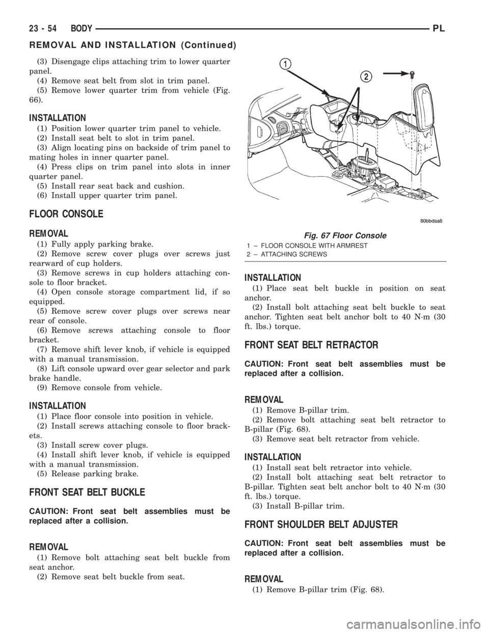
(5) Remove lower quarter trim from vehicle (Fig.
66).
INSTALLATION
(1) Position lower quarter trim panel to vehicle.
(2) Install seat belt to slot in trim panel.
(3) Align locating pins on backside of trim panel to
mating holes in inner quarter panel.
(4) Press clips on trim panel into slots in inner
quarter panel.
(5) Install rear seat back and cushion.
(6) Install upper quarter trim panel.
FLOOR CONSOLE
REMOVAL
(1) Fully apply parking brake.
(2) Remove screw cover plugs over screws just
rearward of cup holders.
(3) Remove screws in cup holders attaching con-
sole to floor bracket.
(4) Open console storage compartment lid, if so
equipped.
(5) Remove screw cover plugs over screws near
rear of console.
(6) Remove screws attaching console to floor
bracket.
(7) Remove shift lever knob, if vehicle is equipped
with a manual transmission.
(8) Lift console upward over gear selector and park
brake handle.
(9) Remove console from vehicle.
INSTALLATION
(1) Place floor console into position in vehicle.
(2) Install screws attaching console to floor brack-
ets.
(3) Install screw cover plugs.
(4) Install shift lever knob, if vehicle is equipped
with a manual transmission.
(5) Release parking brake.
FRONT SEAT BELT BUCKLE
CAUTION: Front seat belt assemblies must be
replaced after a collision.
REMOVAL
(1) Remove bolt attaching seat belt buckle from
seat anchor.
(2) Remove seat belt buckle from seat.
INSTALLATION
(1) Place seat belt buckle in position on seat
anchor.
(2) Install bolt attaching seat belt buckle to seat
anchor. Tighten seat belt anchor bolt to 40 N´m (30
ft. lbs.) torque.
FRONT SEAT BELT RETRACTOR
CAUTION: Front seat belt assemblies must be
replaced after a collision.
REMOVAL
(1) Remove B-pillar trim.
(2) Remove bolt attaching seat belt retractor to
B-pillar (Fig. 68).
(3) Remove seat belt retractor from vehicle.
INSTALLATION
(1) Install seat belt retractor into vehicle.
(2) Install bolt attaching seat belt retractor to
B-pillar. Tighten seat belt anchor bolt to 40 N´m (30
ft. lbs.) torque.
(3) Install B-pillar trim.
FRONT SHOULDER BELT ADJUSTER
CAUTION: Front seat belt assemblies must be
replaced after a collision.
REMOVAL
(1) Remove B-pillar trim (Fig. 68).
Fig. 67 Floor Console
1 ± FLOOR CONSOLE WITH ARMREST
2 ± ATTACHING SCREWS
23 - 54 BODYPL
REMOVAL AND INSTALLATION (Continued)
Page 1172 of 1285
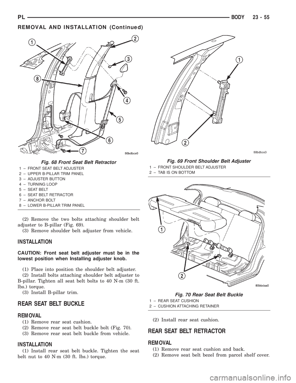
(2) Remove the two bolts attaching shoulder belt
adjuster to B-pillar (Fig. 69).
(3) Remove shoulder belt adjuster from vehicle.
INSTALLATION
CAUTION: Front seat belt adjuster must be in the
lowest position when Installing adjuster knob.
(1) Place into position the shoulder belt adjuster.
(2) Install bolts attaching shoulder belt adjuster to
B-pillar. Tighten all seat belt bolts to 40 N´m (30 ft.
lbs.) torque.
(3) Install B-pillar trim.
REAR SEAT BELT BUCKLE
REMOVAL
(1) Remove rear seat cushion.
(2) Remove rear seat belt buckle bolt (Fig. 70).
(3) Remove rear seat belt buckle from vehicle.
INSTALLATION
(1) Install rear seat belt buckle. Tighten the seat
belt nut to 40 N´m (30 ft. lbs.) torque.(2) Install rear seat cushion.
REAR SEAT BELT RETRACTOR
REMOVAL
(1) Remove rear seat cushion and back.
(2) Remove seat belt bezel from parcel shelf cover.
Fig. 68 Front Seat Belt Retractor
1 ± FRONT SEAT BELT ADJUSTER
2 ± UPPER B-PILLAR TRIM PANEL
3 ± ADJUSTER BUTTON
4 ± TURNING LOOP
5 ± SEAT BELT
6 ± SEAT BELT RETRACTOR
7 ± ANCHOR BOLT
8 ± LOWER B-PILLAR TRIM PANEL
Fig. 69 Front Shoulder Belt Adjuster
1 ± FRONT SHOULDER BELT ADJUSTER
2 ± TAB IS ON BOTTOM
Fig. 70 Rear Seat Belt Buckle
1 ± REAR SEAT CUSHION
2 ± CUSHION ATTACHING RETAINER
PLBODY 23 - 55
REMOVAL AND INSTALLATION (Continued)
Page 1173 of 1285
(3) Remove rear seat closure panel silencer pad as
necessary to gain access to retractor.
(4) Remove bolt attaching seat belt lower anchor to
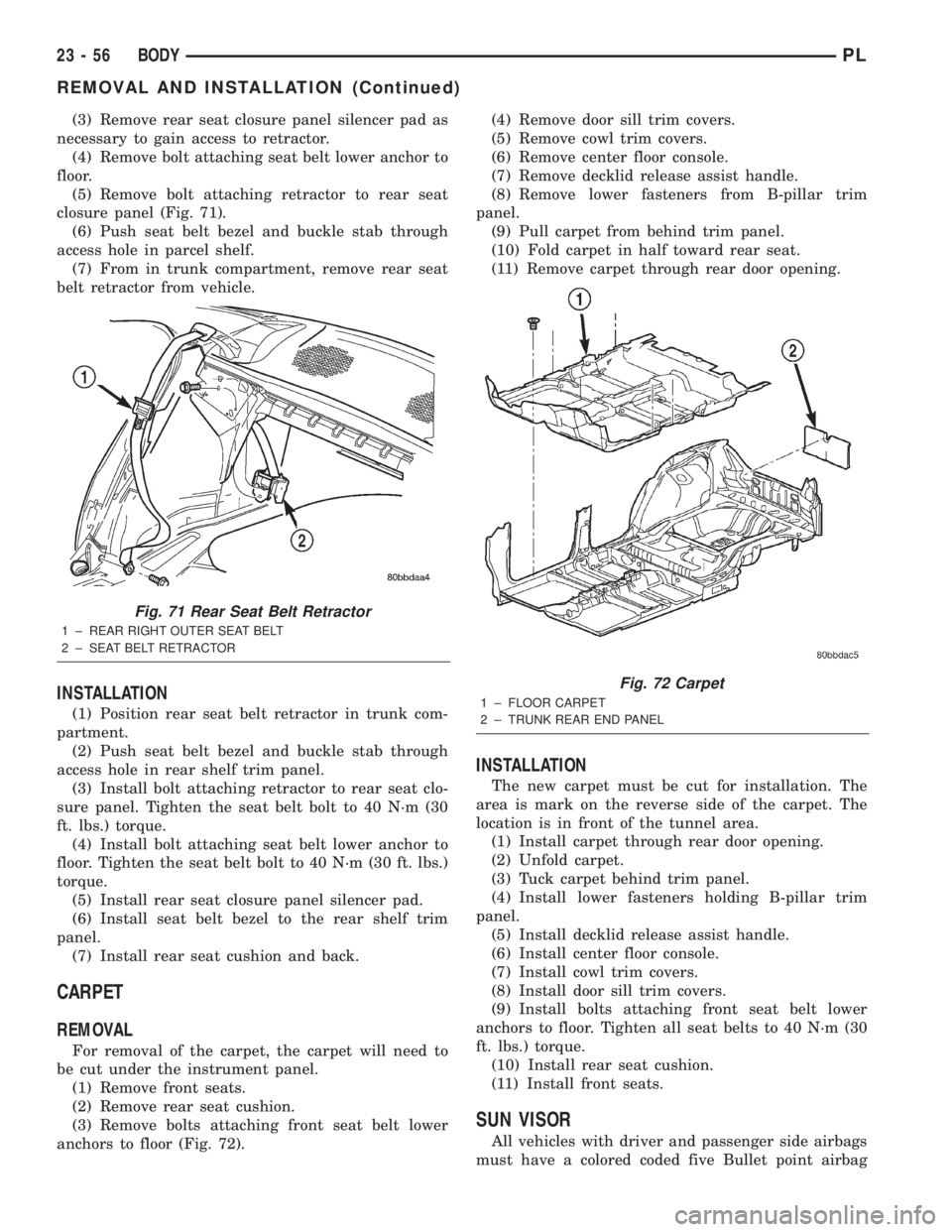
floor.
(5) Remove bolt attaching retractor to rear seat
closure panel (Fig. 71).
(6) Push seat belt bezel and buckle stab through
access hole in parcel shelf.
(7) From in trunk compartment, remove rear seat
belt retractor from vehicle.
INSTALLATION
(1) Position rear seat belt retractor in trunk com-
partment.
(2) Push seat belt bezel and buckle stab through
access hole in rear shelf trim panel.
(3) Install bolt attaching retractor to rear seat clo-
sure panel. Tighten the seat belt bolt to 40 N´m (30
ft. lbs.) torque.
(4) Install bolt attaching seat belt lower anchor to
floor. Tighten the seat belt bolt to 40 N´m (30 ft. lbs.)
torque.
(5) Install rear seat closure panel silencer pad.
(6) Install seat belt bezel to the rear shelf trim
panel.
(7) Install rear seat cushion and back.
CARPET
REMOVAL
For removal of the carpet, the carpet will need to
be cut under the instrument panel.
(1) Remove front seats.
(2) Remove rear seat cushion.
(3) Remove bolts attaching front seat belt lower
anchors to floor (Fig. 72).(4) Remove door sill trim covers.
(5) Remove cowl trim covers.
(6) Remove center floor console.
(7) Remove decklid release assist handle.
(8) Remove lower fasteners from B-pillar trim
panel.
(9) Pull carpet from behind trim panel.
(10) Fold carpet in half toward rear seat.
(11) Remove carpet through rear door opening.
INSTALLATION
The new carpet must be cut for installation. The
area is mark on the reverse side of the carpet. The
location is in front of the tunnel area.
(1) Install carpet through rear door opening.
(2) Unfold carpet.
(3) Tuck carpet behind trim panel.
(4) Install lower fasteners holding B-pillar trim
panel.
(5) Install decklid release assist handle.
(6) Install center floor console.
(7) Install cowl trim covers.
(8) Install door sill trim covers.
(9) Install bolts attaching front seat belt lower
anchors to floor. Tighten all seat belts to 40 N´m (30
ft. lbs.) torque.
(10) Install rear seat cushion.
(11) Install front seats.
SUN VISOR
All vehicles with driver and passenger side airbags
must have a colored coded five Bullet point airbag
Fig. 71 Rear Seat Belt Retractor
1 ± REAR RIGHT OUTER SEAT BELT
2 ± SEAT BELT RETRACTOR
Fig. 72 Carpet
1 ± FLOOR CARPET
2 ± TRUNK REAR END PANEL
23 - 56 BODYPL
REMOVAL AND INSTALLATION (Continued)
Page 1174 of 1285
warning label applied to the sun visor, verify label
availability and ensure the label is installed.
REMOVAL
(1) Remove sun visor from center support.
(2) Remove screws attaching sun visor to roof
header.
(3) Remove sun visor from header.
(4) If equipped, disconnect wire connector from
body harness.
(5) Remove sun visor from vehicle.
INSTALLATION
(1) Place sun visor in position.
(2) If equipped, connect wire connector from body
harness.
(3) Install screws attaching sun visor to header.
(4) Install sun visor into center support.
HEADLINER
REMOVAL
(1) Remove screws attaching sun visors to roof
header panel.
(2) Disconnect wire connector from lighted vanity
mirror, if so equipped.
(3) Remove sun visors from vehicle.
(4) Remove A-pillar trim covers.
(5) Remove B-pillar trim panels.
(6) Remove (upper) quarter panel trim panels.
(7) Remove assist handle, if so equipped.
(8) Remove sun visor hooks.
(9) Remove coat hooks, if so equipped.
(10) Remove three push in fasteners at rear of
headliner.
(11) Disengage dome lamp wire connector, at rear
of headliner.
(12) Remove push in fastener attaching wiring to
C-pillar.
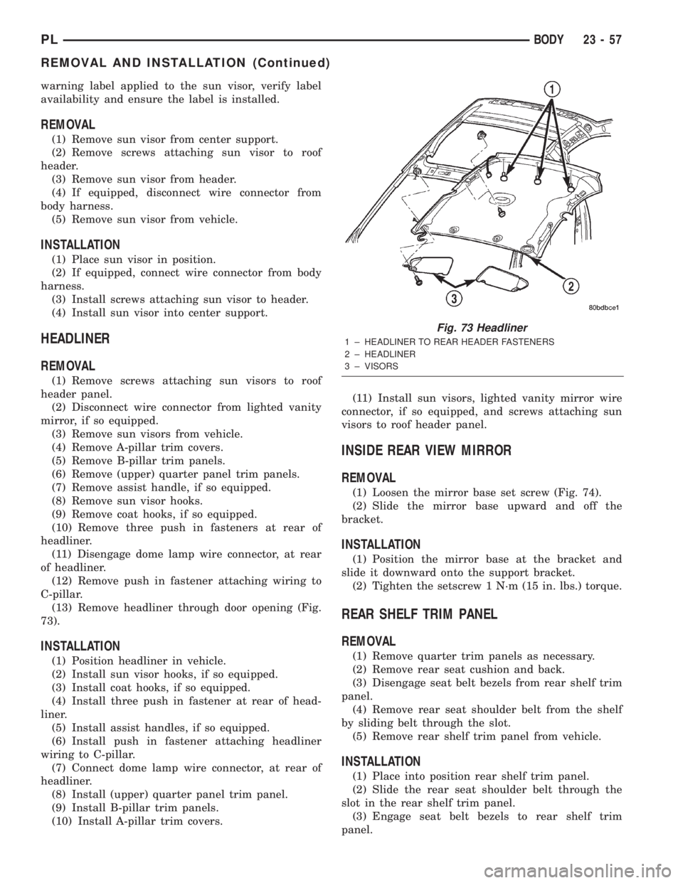
(13) Remove headliner through door opening (Fig.
73).
INSTALLATION
(1) Position headliner in vehicle.
(2) Install sun visor hooks, if so equipped.
(3) Install coat hooks, if so equipped.
(4) Install three push in fastener at rear of head-
liner.
(5) Install assist handles, if so equipped.
(6) Install push in fastener attaching headliner
wiring to C-pillar.
(7) Connect dome lamp wire connector, at rear of
headliner.
(8) Install (upper) quarter panel trim panel.
(9) Install B-pillar trim panels.
(10) Install A-pillar trim covers.(11) Install sun visors, lighted vanity mirror wire
connector, if so equipped, and screws attaching sun
visors to roof header panel.
INSIDE REAR VIEW MIRROR
REMOVAL
(1) Loosen the mirror base set screw (Fig. 74).
(2) Slide the mirror base upward and off the
bracket.
INSTALLATION
(1) Position the mirror base at the bracket and
slide it downward onto the support bracket.
(2) Tighten the setscrew 1 N´m (15 in. lbs.) torque.
REAR SHELF TRIM PANEL
REMOVAL
(1) Remove quarter trim panels as necessary.
(2) Remove rear seat cushion and back.
(3) Disengage seat belt bezels from rear shelf trim
panel.
(4) Remove rear seat shoulder belt from the shelf
by sliding belt through the slot.
(5) Remove rear shelf trim panel from vehicle.
INSTALLATION
(1) Place into position rear shelf trim panel.
(2) Slide the rear seat shoulder belt through the
slot in the rear shelf trim panel.
(3) Engage seat belt bezels to rear shelf trim
panel.
Fig. 73 Headliner
1 ± HEADLINER TO REAR HEADER FASTENERS
2 ± HEADLINER
3 ± VISORS
PLBODY 23 - 57
REMOVAL AND INSTALLATION (Continued)
Page 1193 of 1285
TORQUE SPECIFICATIONS
BODY COMPONENTS
DESCRIPTION TORQUE
All seat belt anchor bolts..... 40N´m(30ft.lbs.)
All seat belt anchor nuts...... 40N´m(30ft.lbs.)
All seat belt retractor bolts.... 40N´m(30ft.lbs.)
Decklid latch striker......... 22N´m(16ft.lbs.)
Front seat track to floor pan bolts . . 55 N´m (40 ft.
lbs.)
Front seat inboard pivot bolt . . . 40 N´m (30 ft. lbs.)
Front seat recliner to seat cushion frame . . 12 N´m
(9 ft. lbs.)
Front seat track to cushion frame bolt . . 12 N´m (9
ft. lbs.)
Front seat back............. 40N´m(30ft.lbs.)DESCRIPTION TORQUE
Front seat back recliner to seat back . 12 N´m (9 ft.
lbs.)
Front door hinge to hinge pillar bolt . 28 N´m (21 ft.
lbs.)
Front door hinge to door nuts and bolt . 28 N´m (21
ft. lbs.)
Front door latch striker....... 28N´m(20ft.lbs.)
Hood latch striker.........13.5 N´m (10 ft. lbs.)
Rear door glass to regulator bolt . . 11 N´m (105 in.
lbs.)
Rear door hinge to B-pillar bolt . 28 N´m (20 ft. lbs.)
Rear door hinge to door bolt . . . 28 N´m (20 ft. lbs.)
Rear door latch striker....... 28N´m(20ft.lbs.)
Rear seat back and seat belt buckle anchor nut . 57
N´m (42 ft. lbs.)
RAIL TO REAR FLOOR PAN
23 - 76 BODYPL
SPECIFICATIONS (Continued)