2000 DODGE NEON engine oil capacity
[x] Cancel search: engine oil capacityPage 3 of 1285
LUBRICANTS AND GREASES
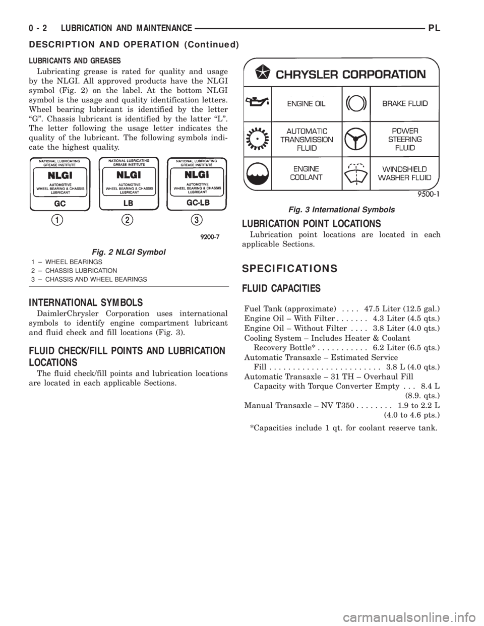
Lubricating grease is rated for quality and usage
by the NLGI. All approved products have the NLGI
symbol (Fig. 2) on the label. At the bottom NLGI
symbol is the usage and quality identification letters.
Wheel bearing lubricant is identified by the letter
ªGº. Chassis lubricant is identified by the latter ªLº.
The letter following the usage letter indicates the
quality of the lubricant. The following symbols indi-
cate the highest quality.
INTERNATIONAL SYMBOLS
DaimlerChrysler Corporation uses international
symbols to identify engine compartment lubricant
and fluid check and fill locations (Fig. 3).
FLUID CHECK/FILL POINTS AND LUBRICATION
LOCATIONS
The fluid check/fill points and lubrication locations
are located in each applicable Sections.
LUBRICATION POINT LOCATIONS
Lubrication point locations are located in each
applicable Sections.
SPECIFICATIONS
FLUID CAPACITIES
Fuel Tank (approximate)....47.5 Liter (12.5 gal.)
Engine Oil ± With Filter....... 4.3Liter (4.5 qts.)
Engine Oil ± Without Filter.... 3.8Liter (4.0 qts.)
Cooling System ± Includes Heater & Coolant
Recovery Bottle*........... 6.2Liter (6.5 qts.)
Automatic Transaxle ± Estimated Service
Fill........................ 3.8L(4.0 qts.)
Automatic Transaxle ± 31 TH ± Overhaul Fill
Capacity with Torque Converter Empty . . . 8.4 L
(8.9. qts.)
Manual Transaxle ± NV T350........ 1.9to2.2L
(4.0 to 4.6 pts.)
*Capacities include 1 qt. for coolant reserve tank.
Fig. 2 NLGI Symbol
1 ± WHEEL BEARINGS
2 ± CHASSIS LUBRICATION
3 ± CHASSIS AND WHEEL BEARINGS
Fig. 3 International Symbols
0 - 2 LUBRICATION AND MAINTENANCEPL
DESCRIPTION AND OPERATION (Continued)
Page 180 of 1285
COOLING SYSTEM
TABLE OF CONTENTS
page page
DESCRIPTION AND OPERATION
COOLING SYSTEM........................1
COOLANT...............................2
COOLANT PERFORMANCE..................2
COOLANT RECOVERY SYSTEM..............3
ENGINE THERMOSTAT.....................3
RADIATOR..............................3
RADIATOR COOLING FAN MODULE...........3
COOLING SYSTEM PRESSURE CAP..........4
RADIATOR HOSES AND CLAMPS............5
WATER PUMP...........................5
AUTOMATIC TRANSMISSION OIL COOLER.....6
ACCESSORY DRIVE BELTS.................6
ENGINE BLOCK HEATER...................6
DIAGNOSIS AND TESTING
COOLING SYSTEM DIAGNOSIS..............7
ENGINE THERMOSTAT TESTING............14
ACCESSORY DRIVE BELT DIAGNOSIS........14
WATER PUMP DIAGNOSIS................15
COOLING SYSTEM FLOW CHECK...........15
ELECTRIC FAN MOTOR TEST...............15
COOLANT CONCENTRATION TESTING........15
TESTING COOLING SYSTEM FOR LEAKS.....15
PRESSURE CAP TO FILLER NECK SEAL
PRESSURE RELIEF CHECK...............16
PRESSURE TESTING COOLING SYSTEM
PRESSURE CAP.......................16
LOW COOLANT LEVEL AERATION...........17
DEAERATION...........................17
TEMPERATURE GAUGE INDICATION.........17
ENGINE BLOCK HEATER..................17
SERVICE PROCEDURES
COOLANT LEVEL CHECKÐROUTINE.........17COOLANTÐADDING ADDITIONAL...........18
COOLANT LEVELÐSERVICING.............18
COOLING SYSTEMÐDRAINING.............19
COOLING SYSTEMÐREFILLING............19
REMOVAL AND INSTALLATION
WATER PUMP..........................19
WATER PUMP INLET TUBE................20
ENGINE THERMOSTAT....................20
RADIATOR.............................21
RADIATOR DRAINCOCK...................22
COOLING FAN MODULE...................22
COOLANT RECOVERY CONTAINER..........23
ENGINE BLOCK HEATER..................24
ACCESSORY DRIVE BELTS................24
AUTOMATIC BELT TENSIONER & PULLEY....26
DISASSEMBLY AND ASSEMBLY
COOLING FAN MODULE...................26
CLEANING AND INSPECTION
WATER PUMP..........................28
ACCESSORY DRIVE BELT INSPECTION.......28
COOLING SYSTEM CAP...................28
COOLING SYSTEM CLEANING..............28
RADIATOR FLUSHING....................28
REVERSE FLUSHING.....................29
CHEMICAL CLEANING....................29
ADJUSTMENTS
BELT TENSION..........................29
SPECIFICATIONS
COOLING SYSTEM CAPACITY..............30
TORQUE SPECIFICATIONS.................30
SPECIAL TOOLS
COOLING..............................30
DESCRIPTION AND OPERATION
COOLING SYSTEM
The cooling system consists of an engine cooling
module, thermostat, coolant, and a water pump to
circulate the coolant. The engine cooling module may
consist of a radiator, electric fan motor, fan, shroud,
coolant reserve system, transmission oil cooler, hoses,clamps, air conditioning condenser and transmission
oil lines.
²When the Engine is cold: The thermostat is
closed and the cooling system has no flow through
the radiator. The coolant flows through the engine,
heater system and bypass.
²When the Engine is warm: Thermostat is open
and the cooling system has flow through the radiator,
engine, heater system, and bypass.
PLCOOLING SYSTEM 7 - 1
Page 740 of 1285
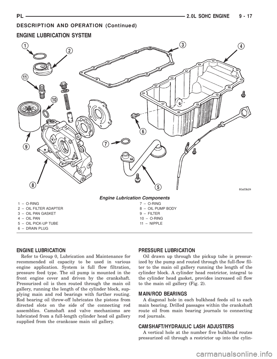
ENGINE LUBRICATION SYSTEM
ENGINE LUBRICATION
Refer to Group 0, Lubrication and Maintenance for
recommended oil capacity to be used in various
engine application. System is full flow filtration,
pressure feed type. The oil pump is mounted in the
front engine cover and driven by the crankshaft.
Pressurized oil is then routed through the main oil
gallery, running the length of the cylinder block, sup-
plying main and rod bearings with further routing.
Rod bearing oil throw-off lubricates the pistons from
directed slots on the side of the connecting rod
assemblies. Camshaft and valve mechanisms are
lubricated from a full-length cylinder head oil gallery
supplied from the crankcase main oil gallery.
PRESSURE LUBRICATION
Oil drawn up through the pickup tube is pressur-
ized by the pump and routed through the full-flow fil-
ter to the main oil gallery running the length of the
cylinder block. A cylinder head restrictor, integral to
the cylinder head gasket, provides increased oil flow
to the main oil gallery (Fig. 2).
MAIN/ROD BEARINGS
A diagonal hole in each bulkhead feeds oil to each
main bearing. Drilled passages within the crankshaft
route oil from main bearing journals to connecting
rod journals.
CAMSHAFT/HYDRAULIC LASH ADJUSTERS
A vertical hole at the number five bulkhead routes
pressurized oil through a restrictor up into the cylin-
Engine Lubrication Components
1 ± O-RING
2 ± OIL FILTER ADAPTER
3 ± OIL PAN GASKET
4 ± OIL PAN
5 ± OIL PICK-UP TUBE
6 ± DRAIN PLUG7 ± O-RING
8 ± OIL PUMP BODY
9 ± FILTER
10 ± O-RING
11 ± NIPPLE
PL2.0L SOHC ENGINE 9 - 17
DESCRIPTION AND OPERATION (Continued)
Page 915 of 1285
ferential case transfers torque from the ring gear to the
drive axles by means of differential side gears.
The NV T350 (A-578) transaxle internal components
can only be serviced by separating the case halves.
CAUTION: The transaxle output shaft is serviced as
a unit. No disassembly and reassembly is possible.
Damage to the transaxle may result.
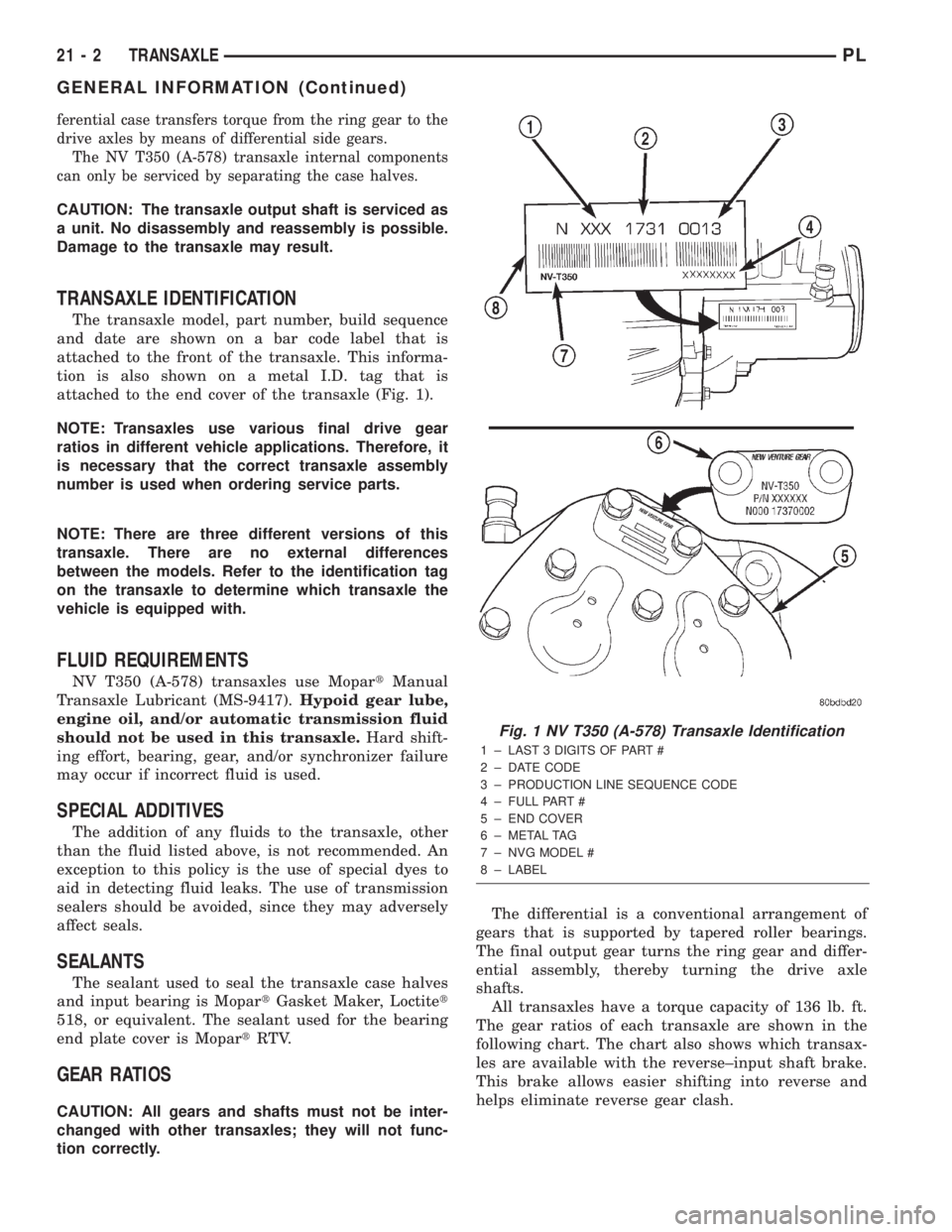
TRANSAXLE IDENTIFICATION
The transaxle model, part number, build sequence
and date are shown on a bar code label that is
attached to the front of the transaxle. This informa-
tion is also shown on a metal I.D. tag that is
attached to the end cover of the transaxle (Fig. 1).
NOTE: Transaxles use various final drive gear
ratios in different vehicle applications. Therefore, it
is necessary that the correct transaxle assembly
number is used when ordering service parts.
NOTE: There are three different versions of this
transaxle. There are no external differences
between the models. Refer to the identification tag
on the transaxle to determine which transaxle the
vehicle is equipped with.
FLUID REQUIREMENTS
NV T350 (A-578) transaxles use MopartManual
Transaxle Lubricant (MS-9417).Hypoid gear lube,
engine oil, and/or automatic transmission fluid
should not be used in this transaxle.Hard shift-
ing effort, bearing, gear, and/or synchronizer failure
may occur if incorrect fluid is used.
SPECIAL ADDITIVES
The addition of any fluids to the transaxle, other
than the fluid listed above, is not recommended. An
exception to this policy is the use of special dyes to
aid in detecting fluid leaks. The use of transmission
sealers should be avoided, since they may adversely
affect seals.
SEALANTS
The sealant used to seal the transaxle case halves
and input bearing is MopartGasket Maker, Loctitet
518, or equivalent. The sealant used for the bearing
end plate cover is MopartRTV.
GEAR RATIOS
CAUTION: All gears and shafts must not be inter-
changed with other transaxles; they will not func-
tion correctly.The differential is a conventional arrangement of
gears that is supported by tapered roller bearings.
The final output gear turns the ring gear and differ-
ential assembly, thereby turning the drive axle
shafts.
All transaxles have a torque capacity of 136 lb. ft.
The gear ratios of each transaxle are shown in the
following chart. The chart also shows which transax-
les are available with the reverse±input shaft brake.
This brake allows easier shifting into reverse and
helps eliminate reverse gear clash.
Fig. 1 NV T350 (A-578) Transaxle Identification
1 ± LAST 3 DIGITS OF PART #
2 ± DATE CODE
3 ± PRODUCTION LINE SEQUENCE CODE
4 ± FULL PART #
5 ± END COVER
6 ± METAL TAG
7 ± NVG MODEL #
8 ± LABEL
21 - 2 TRANSAXLEPL
GENERAL INFORMATION (Continued)
Page 917 of 1285
LOW LUBRICANT LEVEL
Insufficient transaxle lubricant is usually the
result of leaks, or inaccurate fluid level check or refill
method. Leakage is evident by the presence of oil
around the leak point. If leakage is not evident, the
condition is probably the result of an underfill.
If air±powered lubrication equipment is used to fill
a transaxle, be sure the equipment is properly cali-
brated. Equipment out of calibration can lead to an
underfill condition.
FLUID LEAKS
Fluid leaks can occur around the input shaft seal,
axleshaft seals, case split lines, and the end cover. Be
careful not to misdiagnose an input shaft seal leak
for an engine rear main seal leak. Also, the transaxle
case sealer (split line) will accumulate dirt and look
like an oil leak.
CLUTCH PROBLEMS
Worn, damaged, or misaligned clutch components
can cause difficult shifting, gear clash, and noise.
A worn or damaged clutch disc, pressure plate, or
release bearing can cause hard shifting and gear
clash.
SERVICE PROCEDURES
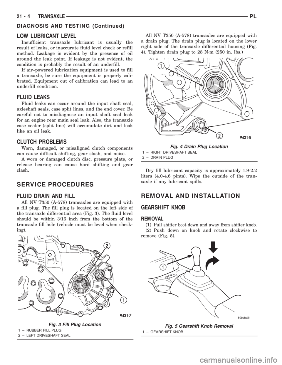
FLUID DRAIN AND FILL
All NV T350 (A-578) transaxles are equipped with
a fill plug. The fill plug is located on the left side of
the transaxle differential area (Fig. 3). The fluid level
should be within 3/16 inch from the bottom of the
transaxle fill hole (vehicle must be level when check-
ing).All NV T350 (A-578) transaxles are equipped with
a drain plug. The drain plug is located on the lower
right side of the transaxle differential housing (Fig.
4). Tighten drain plug to 28 N´m (250 in. lbs.)
Dry fill lubricant capacity is approximately 1.9-2.2
liters (4.0-4.6 pints). Wipe the outside of the tran-
saxle if any lubricant spills.
REMOVAL AND INSTALLATION
GEARSHIFT KNOB
REMOVAL
(1)Pull shifter boot down and away from shifter knob.
(2) Push down on knob and rotate clockwise to
remove (Fig. 5).
Fig. 3 Fill Plug Location
1 ± RUBBER FILL PLUG
2 ± LEFT DRIVESHAFT SEAL
Fig. 4 Drain Plug Location
1 ± RIGHT DRIVESHAFT SEAL
2 ± DRAIN PLUG
Fig. 5 Gearshift Knob Removal
1 ± GEARSHIFT KNOB
21 - 4 TRANSAXLEPL
DIAGNOSIS AND TESTING (Continued)
Page 984 of 1285
(4) Clean the oil pan and magnet. Reinstall pan
using new Mopar Silicone Adhesive sealant. Tighten
oil pan bolts to 19 N´m (165 in. lbs.).
(5) Pour four quarts of MopartATF+4 (Automatic
Transmission Fluid) Type 9602 through the dipstick
opening.
(6) Start engine and allow to idle for at least one
minute. Then, with parking and service brakes
applied, move selector lever momentarily to each
position, ending in the park or neutral position.
(7) Check the transaxle fluid level and add an
appropriate amount to bring the transaxle fluid level
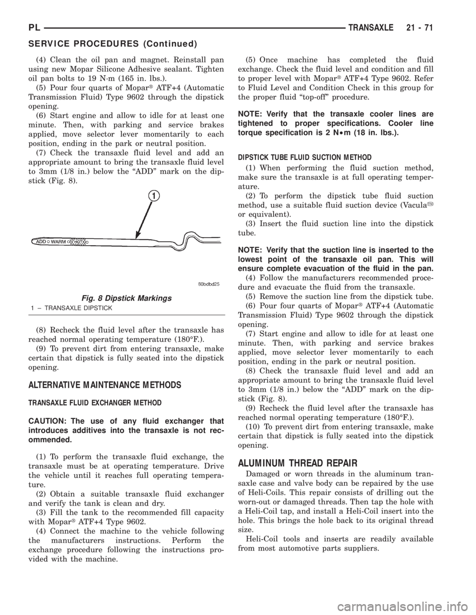
to 3mm (1/8 in.) below the ªADDº mark on the dip-
stick (Fig. 8).
(8) Recheck the fluid level after the transaxle has
reached normal operating temperature (180ÉF.).
(9) To prevent dirt from entering transaxle, make
certain that dipstick is fully seated into the dipstick
opening.
ALTERNATIVE MAINTENANCE METHODS
TRANSAXLE FLUID EXCHANGER METHOD
CAUTION: The use of any fluid exchanger that
introduces additives into the transaxle is not rec-
ommended.
(1) To perform the transaxle fluid exchange, the
transaxle must be at operating temperature. Drive
the vehicle until it reaches full operating tempera-
ture.
(2) Obtain a suitable transaxle fluid exchanger
and verify the tank is clean and dry.
(3) Fill the tank to the recommended fill capacity
with MopartATF+4 Type 9602.
(4) Connect the machine to the vehicle following
the manufacturers instructions. Perform the
exchange procedure following the instructions pro-
vided with the machine.(5) Once machine has completed the fluid
exchange. Check the fluid level and condition and fill
to proper level with MopartATF+4 Type 9602. Refer
to Fluid Level and Condition Check in this group for
the proper fluid ªtop-offº procedure.
NOTE: Verify that the transaxle cooler lines are
tightened to proper specifications. Cooler line
torque specification is 2 N²m (18 in. lbs.).
DIPSTICK TUBE FLUID SUCTION METHOD
(1) When performing the fluid suction method,
make sure the transaxle is at full operating temper-
ature.
(2) To perform the dipstick tube fluid suction
method, use a suitable fluid suction device (Vaculay
or equivalent).
(3) Insert the fluid suction line into the dipstick
tube.
NOTE: Verify that the suction line is inserted to the
lowest point of the transaxle oil pan. This will
ensure complete evacuation of the fluid in the pan.
(4) Follow the manufacturers recommended proce-
dure and evacuate the fluid from the transaxle.
(5) Remove the suction line from the dipstick tube.
(6) Pour four quarts of MopartATF+4 (Automatic
Transmission Fluid) Type 9602 through the dipstick
opening.
(7) Start engine and allow to idle for at least one
minute. Then, with parking and service brakes
applied, move selector lever momentarily to each
position, ending in the park or neutral position.
(8) Check the transaxle fluid level and add an
appropriate amount to bring the transaxle fluid level
to 3mm (1/8 in.) below the ªADDº mark on the dip-
stick (Fig. 8).
(9) Recheck the fluid level after the transaxle has
reached normal operating temperature (180ÉF.).
(10) To prevent dirt from entering transaxle, make
certain that dipstick is fully seated into the dipstick
opening.
ALUMINUM THREAD REPAIR
Damaged or worn threads in the aluminum tran-
saxle case and valve body can be repaired by the use
of Heli-Coils. This repair consists of drilling out the
worn-out or damaged threads. Then tap the hole with
a Heli-Coil tap, and install a Heli-Coil insert into the
hole. This brings the hole back to its original thread
size.
Heli-Coil tools and inserts are readily available
from most automotive parts suppliers.
Fig. 8 Dipstick Markings
1 ± TRANSAXLE DIPSTICK
PLTRANSAXLE 21 - 71
SERVICE PROCEDURES (Continued)
Page 1104 of 1285
The PCM is programmed to maintain the optimum
air/fuel ratio of 14.7 to 1. This is done by making
short term corrections in the fuel injector pulse width
based on the O2S output. The programmed memory
acts as a self calibration tool that the engine control-
ler uses to compensate for variations in engine spec-
ifications, sensor tolerances and engine fatigue over
the life span of the engine. By monitoring the actual
air-fuel ratio with the O2S (short term) and multiply-
ing that with the program long-term (adaptive) mem-
ory and comparing that to the limit, it can be
determined whether it will pass an emissions test. If
a malfunction occurs such that the PCM cannot
maintain the optimum A/F ratio, then the MIL will
be illuminated.
Monitor OperationÐFuel systems monitors do
not have a pre-test because they are continuously
running monitors. Therefore, the PCM constantly
monitors Short Term Compensation and Long Term
Adaptive memory.
Lean: If at anytime during a lean engine operation,
short term compensation multiplied by long term
adaptive exceeds a certain percentage for an
extended period, the PCM sets a Fuel System Lean
Fault for that trip and a Freeze Frame is entered.
Rich: If at anytime during a rich operation, Short
Term Compensation multiplied by Long Term Adap-
tive is less than a predetermined value, the PCM
checks the Purge Free Cells.
Purge Free Cells are values placed in Adaptive
Memory cells when the EVAP Purge Solenoid is OFF.
Two, three or four Purge Free cells are used. One cor-
responds to an Adaptive Memory cell at idle, the
other to a cell that is off-idle. For example, if a Purge
Free cell is labeled PFC1, it would hold the value for
Adaptive Memory cell C1 under non-purge condi-
tions.
If all Purge Free Cells are less than a certain per-
centage, and the Adaptive Memory factor is less than
a certain percentage, the PCM sets a Fuel System
Rich fault for that trip and a Freeze Frame is
entered.
The Fuel Monitor is a two trip monitor. The PCM
records engine data in Freeze Frame upon setting of
the first fault, or maturing code. When the fuel mon-
itor fails on a second consecutive trip, the code is
matured and the MIL is illuminated. The stored
Freeze Frame data is still from the first fault.
In order for the PCM to extinguish the MIL, the
Fuel Monitor must pass in a Similar Condition Win-
dow. The similar conditions relate to RPM and load.
The engine must be within a predetermined percent-
age of both RPM and load when the monitor runs to
count a good trip. As with all DTCs, three good tripsare required to extinguish the MIL and 40 warm up
cycles are required to erase the DTC. If the engine
does not run in a Similar Conditions Window, the
Task Manager extinguishes the MIL after 80 good
trips.
Enabling ConditionsÐThe following conditions
must be met to operate the fuel control monitor:
²PCM not in fuel crank mode (engine running)
²PCM in Closed Loop fuel control
²Fuel system updating Long Term Adaptive
²Fuel level above 15% of capacity
²Fuel level below 85% of capacity
Pending ConditionsÐThe Fuel Control Monitor
does not operate if the MIL is illuminated for any of
the following:
²Misfire Monitor
²Upstream O2S
²EVAP Purge Solenoid Electrical PCM Self Test
Fault
²Camshaft or Crankshaft Position Sensor
²Fuel Injectors
²Ignition Coil Primary
²Throttle Position (TPS) Sensor
²Engine Coolant Temperature (ECT) Sensor
²Manifold Absolute Pressure (MAP) Sensor
²Idle Air Control (IAC)
²5V Output Too Low
²EGR Monitor
²EGR Solenoid Circuit
²Vehicle Speed Sensor
²Oxygen Sensor Monitor
²Oxygen Sensor Heater Monitor
²Oxygen Sensor Electrical
²Idle Speed Rationality
²Intake Air Temperature
SuspendÐThe Task Manager will suspend
maturing a Fuel System fault if any of the following
are present:
²Oxygen Sensor Response, Priority 1
²O2 Heater, Priority 1
²Misfire Monitor, Priority 2
EVAPORATIVE EMISSIONS MONITOR
LEAK DETECTION PUMP MONITORÐThe
leak detection assembly incorporates two primary
functions: it must detect a leak in the evaporative
system and seal the evaporative system so the leak
detection test can be run.
The primary components within the assembly are:
A three port solenoid that activates both of the func-
tions listed above; a pump which contains a switch,
two check valves and a spring/diaphragm, a canister
vent valve (CVV) seal which contains a spring loaded
vent seal valve.
PLEMISSION CONTROL SYSTEMS 25 - 17
DESCRIPTION AND OPERATION (Continued)
Page 1237 of 1285
COMPRESSOR FRONT SHAFT SEAL
The compressor front shaft seal is not serviceable.
If a leak is detected at the shaft seal, the compressor
must be replaced as a unit.
CONDENSATION DRAIN TUBE
Condensation that accumulates in the evaporator
housing is drained from a tube through the dash and
on to the ground. This tube must be kept open to
prevent condensate water from collecting in the bot-
tom of the housing.
The tapered end of the drain tube is designed to
keep contaminants from entering the heater A/C unit
housing. If the tube is pinched or blocked, condensate
cannot drain, causing water to back up and spill into
the passenger compartment. It is normal to see con-
densate drainage below the vehicle. If the tube is
damaged, it should be replaced.
ENGINE COOLING SYSTEM REQUIREMENTS
To maintain ample temperature levels from the
heating-A/C system, the cooling system must be in
proper working order. Refer to Group 0, Lubrication
and Maintenance or Group 7, Cooling System of this
manual.
The use of a bug screen is not recommended. Any
obstructions forward of the condenser can reduce the
effectiveness of the air conditioning system.
EVAPORATOR PROBE
The evaporator probe can be replaced without hav-
ing to remove the unit housing from the vehicle.
The evaporator probe is located in the unit housing
and placed in the evaporator fins. The probe prevents
evaporator freeze-up. This is done by cycling the com-
pressor clutch OFF when evaporator temperature
drops below freeze point. It cycles ON when the
evaporator temperature rises above freeze point. The
evaporator probe uses a thermistor probe in a capil-
lary tube. The tube is inserted between the evapora-
tor fins in the heater-A/C unit housing.
HANDLING TUBING AND FITTINGS
Kinks in the refrigerant tubing or sharp bends in
the refrigerant hose lines will greatly reduce the
capacity of the entire system. High pressures are pro-
duced in the system when it is operating. Extreme
care must be exercised to make sure that all connec-
tions are pressure tight. Dirt and moisture can enter
the system when it is opened for repair or replace-
ment of lines or components. The refrigerant oil will
absorb moisture readily out of the air. This moisture
will convert into acids within a closed system.CAUTION: The system must be completely empty
before opening any fitting or connection in the
refrigeration system. Open fittings with caution
even after the system has been emptied. If any
pressure is noticed as a fitting is loosened,
retighten fitting and evacuate the system again.
A good rule for the flexible hose lines is to keep
the radius of all bends at least 10 times the diame-
ter of the hose. Sharper bends will reduce the flow
of refrigerant. The flexible hose lines should be
routed so they are at least 3 inches (80 mm) from
the exhaust manifold. Inspect all flexible hose lines
to make sure they are in good condition and prop-
erly routed.
The use of correct wrenches when making con-
nections is very important. Improper wrenches or
improper use of wrenches can damage the fittings.
The internal parts of the A/C system will remain
stable as long as moisture-free refrigerant and
refrigerant oil is used. Abnormal amounts of dirt,
moisture or air can upset the chemical stability.
This may cause operational troubles or even seri-
ous damage if present in more than very small
quantities.
When opening a refrigeration system, have every-
thing you will need to repair the system ready. This
will minimize the amount of time the system must
be opened. Cap or plug all lines and fittings as
soon as they are opened. This will help prevent the
entrance of dirt and moisture. All new lines and
components should be capped or sealed until they
are ready to be used.
All tools, including the refrigerant dispensing
manifold, the manifold gauge set, and test hoses
should be kept clean and dry.
HIGH PRESSURE CUT OUT SWITCH
The high pressure cut out switch is located on the
rear of the compressor (Fig. 7). It turns off the com-
pressor if the system pressure exceeds 3240 kPa (470
psi).
LOW PRESSURE CUT OFF SWITCH
The Low Pressure Cut Off Switch (Fig. 8) monitors
the refrigerant gas pressure on the suction side of
the system. The low pressure cut off switch is located
on the expansion valve. The low pressure cut off
switch turns off voltage to the compressor clutch coil
when refrigerant gas pressure drops to levels that
could damage the compressor. The low pressure cut
out switch is a sealed factory calibrated unit. It must
be replaced if defective.
24 - 6 HEATING AND AIR CONDITIONINGPL
DESCRIPTION AND OPERATION (Continued)