2000 DODGE NEON combination switch
[x] Cancel search: combination switchPage 81 of 1285
DESCRIPTION AND OPERATION
BASE BRAKE SYSTEM OPERATION
When a vehicle needs to be stopped, the driver
applies the brake pedal. The brake pedal pushes the
input rod of the power brake booster into the booster.
The booster uses vacuum to ease pedal effort as force
is transferred through the booster to the master cyl-
inder. The booster's output rod pushes in the master
cylinder's primary and secondary pistons applying
hydraulic pressure through the chassis brake tubes
and proportioning valves (rear only) to the brakes at
each tire and wheel assembly.
Front disc brakes control the braking of the front
wheels; rear braking is controlled by rear drum
brakes as standard equipment. Rear disc brakes and
an antilock brake system (ABS) with traction control
are optional.
The hydraulic brake system is diagonally split on
both the non-antilock and antilock braking systems.
This means the left front and right rear brakes are
on one hydraulic circuit and the right front and left
rear are on the other.
Vehicles equipped with the optional antilock brake
system (ABS) use a system designated Mark 20e.
This system shares most base brake hardware used
on vehicles without ABS. A vehicle equipped with
ABS, however, uses a different master cylinder and
brake tubes. Also included in the ABS system is an
integrated control unit (ICU) and four wheel speed
sensors. These components are described in detail in
the ANTILOCK BRAKE SYSTEM section in this
group of the service manual. All vehicles with ABS
come standard with four-wheel-disc brakes and trac-
tion control.
The parking brakes are hand-operated. When
applied, the parking brake lever pulls on cables that
actuate brake shoes at each rear wheel. The parking
brake lever has an automatic adjusting feature that
takes up any excessive slack in the parking brake
cable system.
BASE BRAKE SYSTEM COMPONENTS
BRAKE PEDAL
A suspended-type brake pedal is used on this vehi-
cle. The pedal pivots on a shaft mounted in the pedal
support bracket under the instrument panel. The
pedal connects to the power brake booster input rod
and pushes it in when the pedal is applied.
The brake pedal and it's pad are serviceable sepa-
rately.
POWER BRAKE BOOSTER
There are two different power brake booster
designs, although externally they appear the same.
All vehicles use a 205 mm tandem diaphragm power
brake booster. The two boosters are internally tuned
differently depending on whether the vehicle is
equipped with the standard front disc/rear drum
brake combination or the optional front disc/rear disc
(four-wheel disc) brake combination. If the power
brake booster requires replacement, be sure it is
replaced with the correct part.
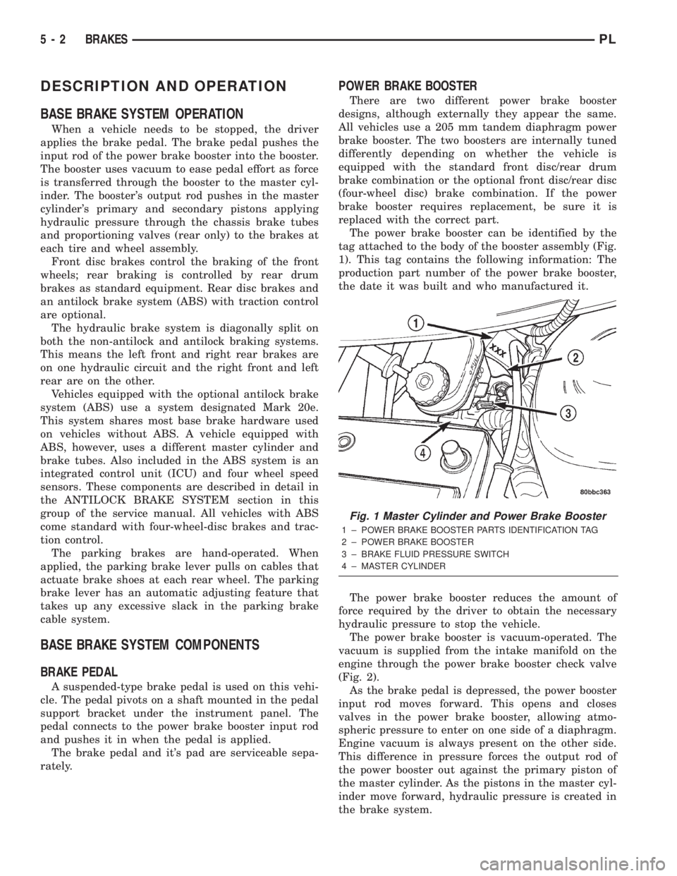
The power brake booster can be identified by the
tag attached to the body of the booster assembly (Fig.
1). This tag contains the following information: The
production part number of the power brake booster,
the date it was built and who manufactured it.
The power brake booster reduces the amount of
force required by the driver to obtain the necessary
hydraulic pressure to stop the vehicle.
The power brake booster is vacuum-operated. The
vacuum is supplied from the intake manifold on the
engine through the power brake booster check valve
(Fig. 2).
As the brake pedal is depressed, the power booster
input rod moves forward. This opens and closes
valves in the power brake booster, allowing atmo-
spheric pressure to enter on one side of a diaphragm.
Engine vacuum is always present on the other side.
This difference in pressure forces the output rod of
the power booster out against the primary piston of
the master cylinder. As the pistons in the master cyl-
inder move forward, hydraulic pressure is created in
the brake system.
Fig. 1 Master Cylinder and Power Brake Booster
1 ± POWER BRAKE BOOSTER PARTS IDENTIFICATION TAG
2 ± POWER BRAKE BOOSTER
3 ± BRAKE FLUID PRESSURE SWITCH
4 ± MASTER CYLINDER
5 - 2 BRAKESPL
Page 292 of 1285
TURN SIGNAL and HAZARD WARNING SYSTEMS
TABLE OF CONTENTS
page page
GENERAL INFORMATION
INTRODUCTION..........................1
DESCRIPTION AND OPERATION
HAZARD WARNING SYSTEM................2
HEADLAMP SWITCH......................2
COMBINATION FLASHER...................2DIAGNOSIS AND TESTING
MULTI-FUNCTION SWITCH.................3
REMOVAL AND INSTALLATION
COMBINATION FLASHER...................5
MULTI-FUNCTION SWITCH.................5
GENERAL INFORMATION
INTRODUCTION
WARNING: ON VEHICLES EQUIPPED WITH AIR-
BAG, SEE GROUP 8M, PASSIVE RESTRAINT SYS-
TEMS FOR AIRBAG REMOVAL.
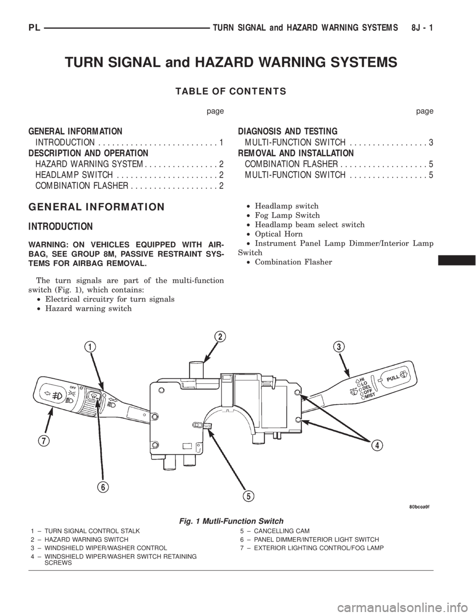
The turn signals are part of the multi-function
switch (Fig. 1), which contains:
²Electrical circuitry for turn signals
²Hazard warning switch²Headlamp switch
²Fog Lamp Switch
²Headlamp beam select switch
²Optical Horn
²Instrument Panel Lamp Dimmer/Interior Lamp
Switch
²Combination Flasher
Fig. 1 Mutli-Function Switch
1 ± TURN SIGNAL CONTROL STALK
2 ± HAZARD WARNING SWITCH
3 ± WINDSHIELD WIPER/WASHER CONTROL
4 ± WINDSHIELD WIPER/WASHER SWITCH RETAINING
SCREWS5 ± CANCELLING CAM
6 ± PANEL DIMMER/INTERIOR LIGHT SWITCH
7 ± EXTERIOR LIGHTING CONTROL/FOG LAMP
PLTURN SIGNAL and HAZARD WARNING SYSTEMS 8J - 1
Page 293 of 1285
The integrated switch assembly is mounted to the
left hand side of the steering column. When the
driver wishes to signal his intentions to change direc-
tion of travel, he moves the lever upward to cause
the right signals to flash and downward to cause the
left signals to flash. After completion of a turn the
system is deactivated automatically. As the steering
wheel returns to the straight ahead position, a can-
celing cam molded to the clockspring mechanism
comes in contact with the cancel actuator on the turn
signal multi-function switch assembly. The cam lobe,
pushing on the cancel actuator, returns the switch to
the off position.
If only momentary signaling such as indication of a
lane change is desired, the switch is actuated to a
left or right intermediate detent position. In this
position the signal lamps flash as described above,
but the switch returns to the OFF position as soon as
the lever is released.
When the system is activated, one of two indicator
lamps mounted in the instrument cluster flashes in
unison with the turn signal lamps, indicating to the
driver that the system is operating.
DESCRIPTION AND OPERATION
HAZARD WARNING SYSTEM
The hazard warning system is actuated by a push
button located in the muti-function switch (Fig. 1) on
the top of the steering column between the steering
wheel and the instrument panel. The hazard switch
is identified with a double triangle on front of the
button.
HEADLAMP SWITCH
The headlamp switch is part of the Multi-Function
Switch (Fig. 1). Refer to Multi-Function Switch Diag-
nosis and Testing, Turn Signal and Hazard Warning
Flasher Diagnosis table in this section.
COMBINATION FLASHER
The turn signal flasher and the hazard warning
flasher are combined into one unit called a combina-
tion flasher (combo-flasher). The combo- flasher con-
trols the flashing of the hazard warning system and
the turn signal system. An inoperative bulb or incom-
plete turn signal circuit will cause the flasher rate to
double.
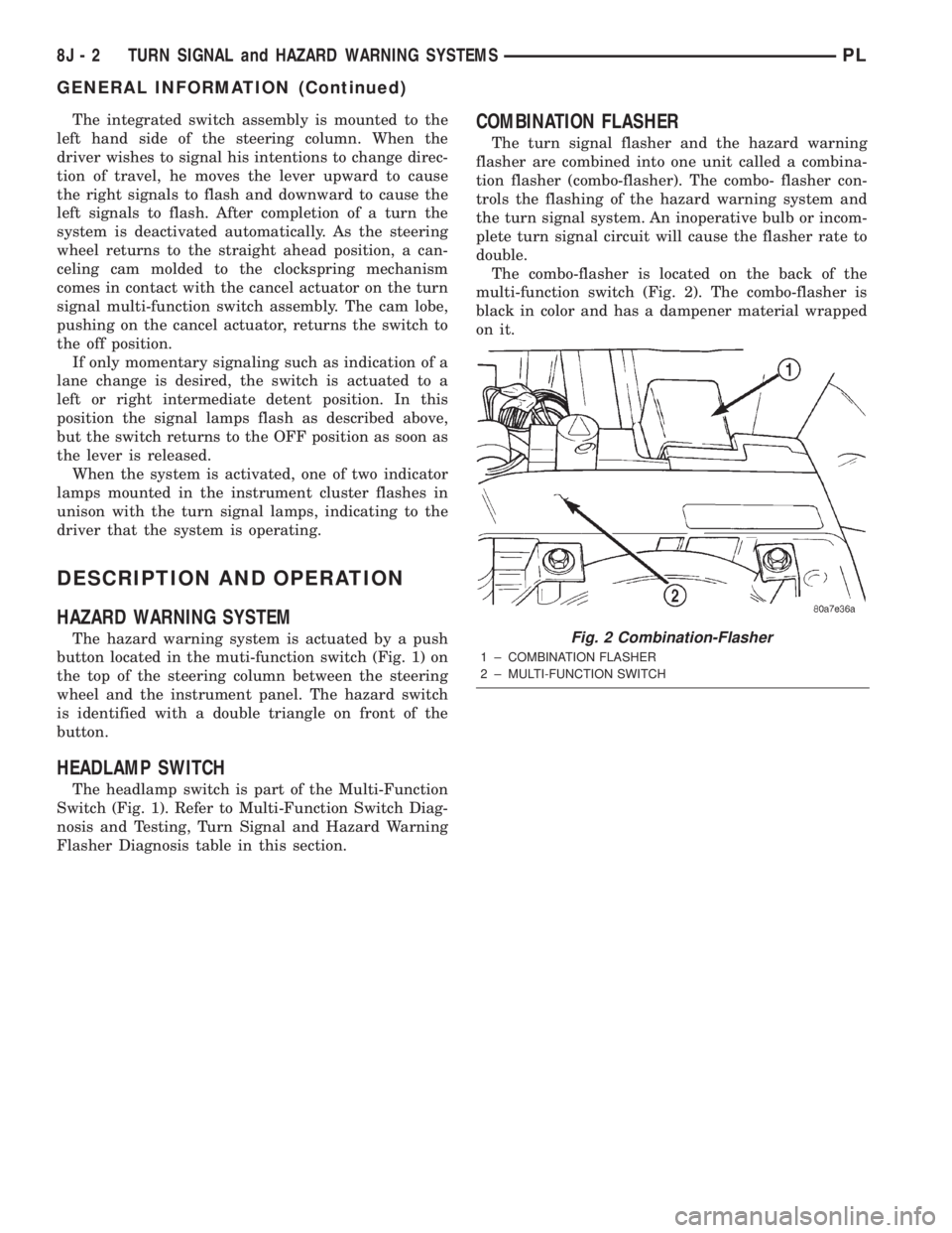
The combo-flasher is located on the back of the
multi-function switch (Fig. 2). The combo-flasher is
black in color and has a dampener material wrapped
on it.
Fig. 2 Combination-Flasher
1 ± COMBINATION FLASHER
2 ± MULTI-FUNCTION SWITCH
8J - 2 TURN SIGNAL and HAZARD WARNING SYSTEMSPL
GENERAL INFORMATION (Continued)
Page 296 of 1285
REMOVAL AND INSTALLATION
COMBINATION FLASHER
The flasher is mounted to the back side of the
multi-function switch (Fig. 2). To gain access the
upper steering column shroud must be removed.
Refer to Group 8E Instrument Panel Systems, Steer-
ing Column Shroud Removal and Installation. The
flasher can be removed by pulling it toward the
instrument cluster (forward). The flasher is serviced
separately from the multi-function switch.
MULTI-FUNCTION SWITCH
REMOVAL
(1) Disconnect and isolate the battery negative
cable (Fig. 6).
(2) Remove both upper and lower steering column
shrouds. Refer to Group 8E Instrument Panel Sys-
tems, Steering Column Shroud Removal and Instal-
lation.
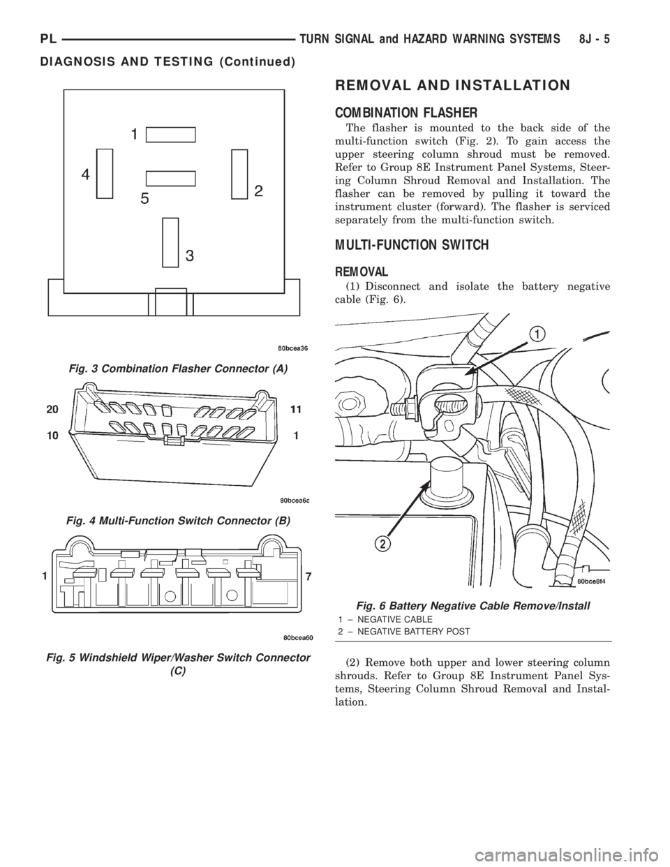
Fig. 3 Combination Flasher Connector (A)
Fig. 4 Multi-Function Switch Connector (B)
Fig. 5 Windshield Wiper/Washer Switch Connector
(C)
Fig. 6 Battery Negative Cable Remove/Install
1 ± NEGATIVE CABLE
2 ± NEGATIVE BATTERY POST
PLTURN SIGNAL and HAZARD WARNING SYSTEMS 8J - 5
DIAGNOSIS AND TESTING (Continued)
Page 297 of 1285
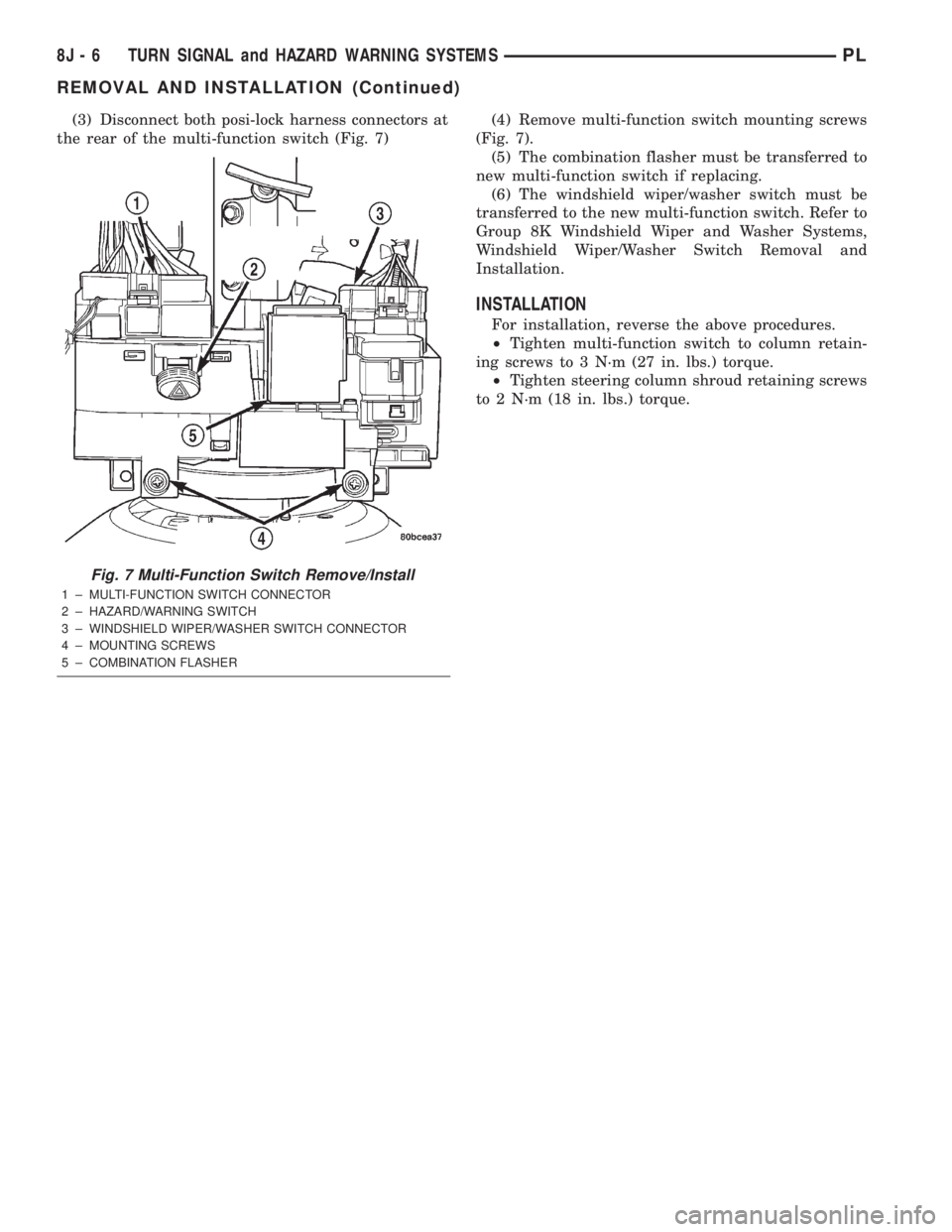
(3) Disconnect both posi-lock harness connectors at
the rear of the multi-function switch (Fig. 7)(4) Remove multi-function switch mounting screws
(Fig. 7).
(5) The combination flasher must be transferred to
new multi-function switch if replacing.
(6) The windshield wiper/washer switch must be
transferred to the new multi-function switch. Refer to
Group 8K Windshield Wiper and Washer Systems,
Windshield Wiper/Washer Switch Removal and
Installation.
INSTALLATION
For installation, reverse the above procedures.
²Tighten multi-function switch to column retain-
ing screws to 3 N´m (27 in. lbs.) torque.
²Tighten steering column shroud retaining screws
to 2 N´m (18 in. lbs.) torque.
Fig. 7 Multi-Function Switch Remove/Install
1 ± MULTI-FUNCTION SWITCH CONNECTOR
2 ± HAZARD/WARNING SWITCH
3 ± WINDSHIELD WIPER/WASHER SWITCH CONNECTOR
4 ± MOUNTING SCREWS
5 ± COMBINATION FLASHER
8J - 6 TURN SIGNAL and HAZARD WARNING SYSTEMSPL
REMOVAL AND INSTALLATION (Continued)
Page 410 of 1285
8W-02 COMPONENT INDEX
Component Page
A/C Compressor Clutch Relay............8W-42
A/C Compressor Clutch.................8W-42
A/C Cycling Switch....................8W-42
A/C Heater Blower Motor...............8W-42
A/C Heater Control....................8W-42
A/C Pressure Switches..................8W-42
Airbag Control Module.................8W-43
Airbags.............................8W-43
Antenna.............................8W-47
Automatic Shut Down Relay.............8W-30
Back-Up Lamp Switch..................8W-51
Back-Up Lamps.......................8W-51
Battery.............................8W-20
Blower Motor Resistor Block.............8W-42
Brake Lamp Switch....................8W-30
Brake Shift Interlock Solenoid...........8W-30
Brake Warning Indicator Switch..........8W-40
Camshaft Position Sensor...............8W-30
Cargo Lamp..........................8W-44
Center High Mounted Stop Lamp.........8W-51
Center Stack Lamp....................8W-44
Cigar Lighter/Power Outlet..............8W-41
Circuit Breakers (FB)..................8W-11
City Lamps..........................8W-50
Clockspring.....................8W-33, 41, 43
Clutch Interlock Switch.................8W-30
Combination Flasher...................8W-52
Controller Anti-Lock Brake..............8W-35
Crankshaft Position Sensor..............8W-30
Data Link Connector...................8W-30
Decklid Release Switch.................8W-44
Decklid Solenoid......................8W-61
Diode No. 1..........................8W-42
Dome Lamp..........................8W-44
Dome Lamp/Intrusion Sensor............8W-44
Door Ajar Switches....................8W-40
Door Lock Motors.....................8W-61
Engine Coolant Temperature Sensor.......8W-30
Engine Oil Pressure Switch..............8W-30
Engine Starter Motor Relay.............8W-21
Engine Starter Motor..................8W-21
Fog Lamps........................8W-50, 51
Front Fog Lamp Switch.................8W-50
Fuel Injectors........................8W-30
Fuel Pump Module....................8W-30
Fuel Pump Relay......................8W-30
Fuel Tank...........................8W-30
Fuses (FB)...........................8W-11
Fuses (PDC).........................8W-10
Fuse Block...........................8W-11
Fusible Link A11...................8W-20, 21
Grounds.............................8W-15Component Page
Generator...........................8W-20
Glove Box Lamp/Switch.................8W-44
Headlamp Beam Select..............8W-40, 50
Headlamp Leveling Motors..............8W-50
Headlamp Leveling Switch Illumination....8W-50
Headlamp Leveling Switch..............8W-50
Headlamp Switch...................8W-50, 51
Headlamps..........................8W-50
Horns..............................8W-41
Horn Relay..........................8W-41
Horn Switch.........................8W-41
Hood Ajar Switch......................8W-39
Idle Air Control Motor..................8W-30
Ignition Coil.........................8W-30
Ignition Switch.......................8W-10
Indicators...........................8W-40
Indicator Drivers......................8W-40
Inlet Air Temperature Sensor............8W-30
Instrument Cluster....................8W-40
Instrument Panel Drivers...............8W-40
Knock Sensor.........................8W-30
Leak Detection Pump..................8W-30
License Lamps........................8W-51
Manifold Absolute Pressure Sensor........8W-30
Map/Reading Lamps...................8W-44
Multi- Function Switch.........8W-40, 50, 51, 52
Noise Suppressor......................8W-30
Oxygen Sensors.......................8W-30
Park Brake Switch....................8W-40
Park/Neutral Position Switch............8W-51
Park/Turn Signal Lamps................8W-52
Power Distribution Center...............8W-10
Power Mirror Switch...................8W-62
Power Steering Pressure Switch..........8W-30
Powertrain Control Module..............8W-30
PRNDL Lamp........................8W-44
Proportional Evap/Purge Solenoid.........8W-30
Radiator Fan Motor....................8W-42
Radiator Fan Relay....................8W-42
Radio...............................8W-47
Rear Window Defogger Switch...........8W-48
Rear Window Defogger.................8W-48
Remote Keyless Entry Module............8W-39
Repeater Lamps......................8W-52
Seat Belt Switch......................8W-40
Sentry Key Immobilizer Module..........8W-39
Side Marker Lamps....................8W-50
Siren...............................8W-39
Speakers............................8W-47
Splice Information.....................8W-70
Sunroof Control Module................8W-64
Sunroof Motor........................8W-64
PL8W - 02 COMPONENT INDEX 8W - 02 - 1
Page 412 of 1285
8W-10 POWER DISTRIBUTION
Component Page
A/C Compressor Clutch Relay........8W-10-7, 16
Automatic Shut Down Relay...........8W-10-16
Battery............................8W-10-7
Brake Lamp Switch................8W-10-7, 18
Cargo Lamp.......................8W-10-12
Center High Mounted Stop Lamp.......8W-10-18
Cigar Lighter/Power Outlet............8W-10-8
Circuit Breaker No. 1 (FB).............8W-10-9
Circuit Breaker No. 2 (FB).............8W-10-9
Combination Flasher.................8W-10-13
Controller Anti-Lock Brake.......8W-10-7, 11, 18
Data Link Connector.................8W-10-16
Dome Lamp.......................8W-10-12
Dome Lamp/Intrusion Sensor..........8W-10-12
Engine Starter Motor.................8W-10-8
Engine Starter Motor Relay........8W-10-7, 8, 10
Front Fog Lamp Switch..............8W-10-14
Fuel Injector No. 1..................8W-10-17
Fuel Injector No. 2..................8W-10-17
Fuel Injector No. 3..................8W-10-17
Fuel Injector No. 4..................8W-10-17
Fuel Pump Module..................8W-10-16
Fuel Pump Relay...................8W-10-16
Fuse 1 (FB)........................8W-10-10
Fuse 2 (FB)........................8W-10-10
Fuse 5 (PDC).......................8W-10-7
Fuse 6 (FB).........................8W-10-9
Fuse 6 (PDC).....................8W-10-7, 11
Fuse 7 (FB).........................8W-10-9
Fuse 8 (FB).........................8W-10-9
Fuse 8 (PDC).....................8W-10-7, 11
Fuse 9 (FB)........................8W-10-10
Fuse 9 (PDC)......................8W-10-7, 8
Fuse 10 (FB).......................8W-10-10
Fuse 10 (PDC)....................8W-10-7, 11
Fuse 11 (FB).......................8W-10-10
Fuse 12 (FB).......................8W-10-10
Fuse 13 (PDC)....................8W-10-7, 12
Fuse 14 (FB)........................8W-10-9
Fuse 14 (PDC).....................8W-10-7, 8
Fuse 15 (FB)........................8W-10-9
Fuse 15 (PDC)....................8W-10-7, 13
Fuse 16 (FB)........................8W-10-9Component Page
Fuse 18 (PDC)....................8W-10-7, 13
Fuse 20 (FB).......................8W-10-11
Fuse 20 (PDC)....................8W-10-7, 14
Fuse 21 (PDC)....................8W-10-7, 16
Fuse 22 (PDC)....................8W-10-7, 16
Fuse 23 (PDC)....................8W-10-7, 18
Fuse Block....................8W-10-9, 10, 11
Generator.........................8W-10-17
Glove Box Lamp/Switch..............8W-10-12
Headlamp Switch...................8W-10-14
High Note Horn....................8W-10-13
Horn Relay......................8W-10-7, 13
Ignition Coil.......................8W-10-17
Ignition Switch................8W-10-7, 8, 9, 10
Instrument Cluster.............8W-10-8, 12, 14
Instrument Panel Drivers.............8W-10-14
Left Front Fog Lamp..............8W-10-14, 15
Left Tail/Stop Lamp.................8W-10-18
Left Tail/Stop/Turn Signal Lamp........8W-10-19
Left Visor/Vanity Lamp...............8W-10-12
Low Note Horn.....................8W-10-13
Map/Reading Lamps.................8W-10-12
Multi-Function Switch......8W-10-7, 13, 14, 15, 19
Noise Suppressor...................8W-10-17
Oxygen Sensor 1/1 Upstream..........8W-10-17
Oxygen Sensor 1/2 Downstream........8W-10-17
Power Distribution Center.....8W-10-2, 3, 4, 7, 8,
9, 11, 12, 13, 14, 16, 18
Powertrain Control Module.........8W-10-16, 17
Radiator Fan Motor.................8W-10-11
Radiator Fan Relay................8W-10-7, 11
Radio.............................8W-10-12
Rear Window Defogger...............8W-10-11
Rear Window Defogger Switch.........8W-10-11
Remote Keyless Entry Module.........8W-10-12
Right Front Fog Lamp...............8W-10-15
Right Rear Fog Lamp................8W-10-14
Right Tail/Stop Lamp................8W-10-18
Right Tail/Stop/Turn Signal Lamp......8W-10-19
Right Visor/Vanity Lamp..............8W-10-12
Sentry Key Immobilizer Module........8W-10-12
Siren.............................8W-10-12
Underhood Lamp...................8W-10-12
PL8W - 10 POWER DISTRIBUTION 8W - 10 - 1
Page 424 of 1285

POWER
DISTRIBUTION
CENTER
15A
FUSE
18
18
2
X2
18
DG/RD 41
4039
X2
18
DG/RD
2C109
HORNS) (DUAL
HORN
NOTE
HIGH
F62
18
RDF62
18
RD
HORN
RELAY
(IN PDC)
43
EXCEPT
EXPORTUP- BUILT-
EXPORTUP- BUILT-
HORN
NOTE
HIGH
DG/RD18 X2
2
LOW
NOTE
HORN
DG/RD18 X2
2
X2
18
DG/RD
BATT A0
15A
FUSE
15
15
11
WT18 A15
6C103B6
A15
20
WT
MULTI-
FUNCTION
SWITCH
FLASHER COMBINATION
(8W-10-2)
(8W-10-3)
(8W-41-2)(8W-41-2)
(8W-41-3)
(8W-41-3) (8W-41-2)
(8W-41-3) (8W-10-7)
(8W-52-3)
(8W-52-4)
(8W-52-7)
(8W-52-9)
(8W-52-10) (8W-52-3)
(8W-52-4)
(8W-52-7)
(8W-52-9)
(8W-52-10)
PL8W-10 POWER DISTRIBUTION 8W - 10 - 13
PLI01013008W-10